EP0712325B1 - Vehicle track for construction toy system - Google Patents
Vehicle track for construction toy system Download PDFInfo
- Publication number
- EP0712325B1 EP0712325B1 EP94922437A EP94922437A EP0712325B1 EP 0712325 B1 EP0712325 B1 EP 0712325B1 EP 94922437 A EP94922437 A EP 94922437A EP 94922437 A EP94922437 A EP 94922437A EP 0712325 B1 EP0712325 B1 EP 0712325B1
- Authority
- EP
- European Patent Office
- Prior art keywords
- rail
- elements
- strut
- track
- spaced
- Prior art date
- Legal status (The legal status is an assumption and is not a legal conclusion. Google has not performed a legal analysis and makes no representation as to the accuracy of the status listed.)
- Expired - Lifetime
Links
Images


Classifications
-
- A—HUMAN NECESSITIES
- A63—SPORTS; GAMES; AMUSEMENTS
- A63H—TOYS, e.g. TOPS, DOLLS, HOOPS OR BUILDING BLOCKS
- A63H18/00—Highways or trackways for toys; Propulsion by special interaction between vehicle and track
- A63H18/02—Construction or arrangement of the trackway
-
- A—HUMAN NECESSITIES
- A63—SPORTS; GAMES; AMUSEMENTS
- A63H—TOYS, e.g. TOPS, DOLLS, HOOPS OR BUILDING BLOCKS
- A63H19/00—Model railways
- A63H19/30—Permanent way; Rails; Rail-joint connections
-
- A—HUMAN NECESSITIES
- A63—SPORTS; GAMES; AMUSEMENTS
- A63H—TOYS, e.g. TOPS, DOLLS, HOOPS OR BUILDING BLOCKS
- A63H33/00—Other toys
- A63H33/04—Building blocks, strips, or similar building parts
Definitions
- This invention relates to a track construction for a construction toy system of the type having at least one rail supported on rail mounting elements.
- the basic construction toy system is comprised of a novel strut and connector system in which connectors are provided with open-sided sockets for the lateral reception and substantially rigid retention of end portions of rod-like strut elements.
- the sockets of the connector elements are defined by spaced-apart gripping arms formed with axially extending grooves which engage and grip opposite sides of a strut adjacent its end to align and firmly hold the strut along a predefined axis.
- One or more locking elements project from the gripping arms partially into the socket area, and these are received in grooves formed on the ends of the struts, such that the struts, when engaged by the gripping arms, are locked against axial motion by co-operation between the projects and grooves.
- the struts are provided with longitudinally extending opposed grooves designed for cooperation with the locking projections formed on the gripping arms of the connector elements. This arrangement enables the struts to be pressed crosswise into the gripping sockets, until the locking projections are snapped into the opposed longitudinal grooves, thus firmly locking the strut in a crosswise orientation in the connecting element.
- WO 81/01799 there is described a track construction for a construction toy system of the aforesaid type.
- lengths of rail section each have a securing aperture adjacent to each end of the rail section so that the two securing apertures in a said rail section are a fixed longitudinal distance apart.
- the securing apertures in a rail section are secured to longitudinally spaced rail mounting elements provided with two pairs of transversely spaced spring clips each resiliently engaging in a respective said securing aperture.
- each of two co-linear first rail sections is secured to a respective spring clip in one of said pairs of clips on a rail mounting element whilst each of two co-linear second rail sections parallel to the first sections is secured to a respective spring clip in the other pair of spring clips on the rail mounting element.
- the rail sections as shown in the document are substantially rigid and are shown as being self-supporting along their whole lengths so that when constituting an incline each rail section extends in a straight line from an upper to a lower level.
- rigidity of the rail sections is enhanced by each being of a substantially rod-shaped body with a rail-forming rib integral with an upper face of the body providing a sort of rigidifying girder flange.
- the longitudinally fixed securing places for the rail sections plus rigidity of the rail sections restricts the shape of the track which can be constructed from the toy.
- An object of the invention is to provide a simple track construction for a construction toy system of the aforesaid type which inherently permits considerable flexibility in track design so that tracks in a wide range of shapes can be constructed readily.
- a track construction for a construction toy system having at least one rail supported on rail mounting elements is characterised by:-
- the track construction allows the rail to be releasably lockingly engaged anywhere along its length.
- the rail can be adjusted with respect to the positioning of the rail mounting elements.
- such a structure is a significant improvement over those disclosed in the prior art such as WO 81/01799 or US 5 118 320, because our structure provides for a greater deal of control over the shape and support of the track whilst providing efficient and adjustable means of mounting and supporting the track.
- the system incorporates specially modified connector elements which, in addition to forming part of an underlying structure, also mount and support guide rails forming a vehicle guide track.
- the new system enables guide tracks to be designed with portions arranged in a straight line manner, and with other portions formed with horizontal curves and vertical contours.
- a respective structure specifically illustrated herein is in the form of roller coaster, which easily illustrates the manner in which the invention can be employed.
- the track system of the invention utilises, for the rail elements of the track structure, generally continuous lengths of modified flexible plastic tubing, which is slotted lengthwise.
- Special connector elements provided for mounting and supporting the rail elements, are formed with integral mounting lugs, each including an upwardly projecting stem portion and an enlarged head portion.
- the rail elements can be assembled to their supports by applying the slotted side of the tubing over the mounting lugs, so that the interior of the tubular rail section is supported by the head portions of the mounting lugs, and the rail section is spaced above the connector element by the stem portion, which passes through the slotted side wall of the rail.
- rail-supporting connector elements are spaced apart longitudinally, and the rail sections are self-supporting in the spaces between longitudinally adjacent connector elements.
- the rail-supporting connector is a modification of an otherwise standard connector element for the construction toy system, which is incorporated in the basic underlying structure and forms part of the structure.
- a connector will sometimes be referred to as a structural connector.
- the system of the invention includes separate clip-like support devices, which attach to the basic underlying structure, but do not form part of the structural framework.
- the rail-supporting clips may be installed anywhere along the length of a strut element underlying the rail path, to support a section of rail which is adjacent thereto.
- the support clips may be slidably adjusted longitudinally along the rod-like strut elements so that the location of the support may be empirically optimized.
- the rod-like strut elements are, in most cases, rotationally adjustable in the structural framework, which facilitates shaping of the rail in horizontal and vertical curved areas.
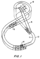
- the reference numeral 10 (Fig. 1) represents generally a typical structure employing the features of the invention.
- the structure 10 is a roller coaster comprised of spaced-apart rails 11, 12 mounted on a skeletal structure 13 comprised of rod-like struts and connector elements, preferably according to the principles and disclosures of the before mentioned Glickman United States patents.
- the rails 11, 12 are spaced-apart uniformly over their entire length, forming a two-rail guide track for one or more wheeled vehicles 14.
- a motorized or manual lift device desirably is provided for carrying the vehicle 14 up an inclined portion 15 of the structure. When the vehicle reaches the top of the incline, it is released and returns by gravity to the bottom of the incline.
- a rail-supporting structure of suitable configuration may be assembled utilizing a plurality of struts 16-19 and transversely disposed spacing struts 20, joined with connector elements 21-23.
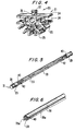
- the connector elements are preferably formed of molded plastic and are provided with a plurality of strut-engaging sockets 24 (Fig. 10).
- the sockets 24 are comprised of spaced-apart gripping arms 25 formed with axially extending grooves 26.
- the sockets 24 are open at one end and closed at the other by an end wall 27.
- Locking projections 28, integral with the gripping arms 25, project slightly into the socket space forming a constriction.
- the several strut elements are provided at each end with a configuration complementary to the sockets 24.
- the strut end includes a cylindrical section 29, an annular grooved portion 30, and an end flange 31.
- the end flanges 31 are adapted to be closely received in an end chamber 32 in the connector socket, formed between the end wall 27 and the locking projections 28.
- the projections 28 are designed to closely conform to the annular groove 30 in the strut, and the cylindrical portions 29 of the struts are adapted to be received in and gripped by the axially grooved portions 26 of the gripping arms 25.
- a strut Normal attachment of a strut to a connecting element involves a lateral snap-in assembly in which the strut end is forced laterally into an open side of the socket 24, with the gripping arms 25 temporarily flexing outward sufficiently to enable the cylindrical portions 29 of the strut to enter into the grooved portions 26. The strut is then firmly gripped and positioned in the socket.
- a strut can also be inserted into the socket in a crosswise orientation.
- central portions of the strut elements are formed with opposed grooves 33, running lengthwise along the struts.
- the positioning of the locking projections 28, in relation to the end wall 27 of the sockets, is such that, when a crosswise oriented strut is pressed into the open end of a socket 24, it can be pressed deep enough into the socket that the locking projections 28 snap into the longitudinal grooves 33, locking the strut firmly in its crosswise orientation.
- the connector elements can be provided in a variety of configurations, with multiple strut-receiving sockets radiating in a single plane, or in multiple planes, to accommodate a wide variety of structural possibilities.
- a structural base is formed by a plurality of flat-sided base connectors 23 joined by horizontal, longitudinally extending struts 17.
- the connector elements 23 be arranged in transversely opposed pairs, as shown in Fig. 3, and these may be joined by transverse spacing struts 20 received crosswise in the connector elements.
- an elevated structure is formed using vertical struts 18, which extend from the base connectors 23 to intermediate connector elements 22. Longitudinally adjacent ones of the intermediate connectors 22 are joined by horizontal struts 17 of the same length as directly below.
- short struts 16 join the intermediate connector 22 with upper, rail-supporting connectors.
- the connectors 21 are, in general, similar to the flat-sided base connectors 23.
- a rail-mounting lug 35 projects upward from the flat sidewall 34 of the connector.
- the lug 35 desirably is integral with the molded connector element 21 and is comprised of an upwardly projecting relatively flat, thin stem portion 36 and an enlarged head portion 37, which typically will be of cylindrical cross section.
- the rail-mounting lug 35 preferably is of relatively short length (measured horizontally in Fig. 4) in comparison with the overall length of the flat sidewall 34.
- the rail element 38 is an elongated section of extruded (or possibly molded) plastic tubing, which is formed with an open side 39 and continuous, divergent guide flanges 39a extending from its opposite edges.
- the tubing preferably is formed by extrusion of a flexible plastic material and, in one advantageous embodiment of the invention, has a hollow interior of approximately 3.18 mm (1/8 inch) diameter and side walls 40 of approximately 0.79 mm (1/32 inch) in thickness.
- a suitable throat width for the slot-like opening 39 is approximately 1.52 mm (0.06 inch).
- the rail-mounting lugs 35 are sized and shaped to be complementary with the rail sections 38.
- the cylindrical head portions 37 of the mounting lugs of approximately 3.18 mm (1/8 inch) diameter, to be received snugly within the 3.18 mm (1/8 inch) internal opening of the tubing.
- the stem portions 37 may have a thickness of, for example, 1.60 mm (0.063 inch), barely larger than the nominal width of the slot opening 39.
- a complete track structure is made of a series of longitudinally joined connector elements 21, providing spaced-apart rail-mounting lugs 35.
- the rail sections 38 ideally are provided in more or less continuous lengths to provide for an uninterrupted rail over the entire length of the assembled structure.
- sections of rail can be joined in any suitable manner, or a single rail section may be joined end to end to form a closed loop. In many cases, it is sufficient merely to apply adjacent ends of a rail section to a common support lug 35.
- a thin rod-like connector plug (not shown) may be inserted into the abutted ends of adjacent rail sections in order to provide a smooth connection and transition.
- tubular rail sections 38 A preferred material for the tubular rail sections 38 is polypropylene, but other materials may be employed.
- the stiffness/flexibility of the rail sections is not critical. For some structures, relatively straight, relatively rigid rail sections may be preferred. In others, relatively flexible sections may be preferred, and some structures may desirably employ a mixture of both relatively rigid and relatively flexible sections, depending upon contours of the structure.
- Horizontal curves may be provided by joining adjacent rail-supporting connectors 21 at opposite sides of the structure using struts of different lengths.
- struts of different lengths.
- longitudinally adjacent connectors 21 at the bottom of the figure are joined by a strut 17 of one size, whereas the corresponding connectors 21 at the opposite side (top of the figure) are joined by a strut 17' of greater length.
- This causes the track structure to be curved slightly toward the bottom of the figure.
- Vertical contours may be imparted by employing vertical connecting struts of different size between the intermediate connectors 22 and the rail-supporting connectors 21.
- the rail-supporting connectors 21 are joined to the structure by struts 16 of minimum length. Over a succession of adjacent segments, the length of the connecting struts 16 may be progressively increased, to cause the track structure to be diverted upwardly. As is evident in Fig. 1, a structure of complex, compound contours may be easily assembled using struts of appropriate lengths to connect adjacent segments of the structure. By using relatively flexible rail sections 38, the contours of the tracks are smooth, with gradual transitions in changing from one direction to another.
- the transverse spacing struts 20 with spacing flanges 42 adjacent to but spaced from cylindrical end portions 29 of the spacing struts (see Fig. 5).
- the longitudinal grooves 33 which normally extend continuously from one end portion 29 to the other, are interrupted by the spacing flanges 42 to define locating sections 43.
- the length of the locating sections is approximately equal to, or slightly greater than the thickness of the connector elements 21, such that an opposed pair of gripping elements 25 can receive the strut 20 in a crosswise orientation within the limits of the spacing section 43.
- spacing strut 20 When the spacing strut 20 is thus joined with the connectors 21, the latter are accurately and uniformly spaced apart, so that the respective rails 11, 12 are maintained in relatively uniform horizontal spacing throughout the full extent of the track structure.
- the spacing struts 20 may of course be utilized in conjunction with any of the connector elements 22 or 23, at intermediate levels or at the base of the structure, as well as the rail-supporting elements at the top of the structure.
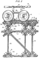
- the new track structure can be utilized with any wheeled vehicle having appropriately flanged wheels 41, as shown particularly in Fig. 3.
- pairs of the flanged wheels 41 are rotatably mounted on horizontal axle struts 44, using single socket connectors 45 at each end to retain the wheels on the struts.
- a vehicle body is made up of longitudinal struts 46 and transverse struts 47, joined at the corners by right angle connectors 48.
- Double-ended connectors 49 grip the longitudinal struts 46 and extend downward to engage longitudinal struts 50.
- Additional right angle connectors 51 are attached to the longitudinal struts 50 and to the axle struts 44 (see Fig. 3) to provide a rudimentary vehicle capable of rolling along the track structure.
- the system of the invention enables a complex, contoured track structure to be assembled.
- the illustrated structure employs a two-rail track structure for supporting a vehicle having two or more wheels.
- Monorail and multiple rail structures are also possible with the system of the invention.
- a feature of particular advantage is the utilization of strut and connector assemblies, providing for lateral snap-in assembly of the struts and connectors to enable complex skeletal structures to be assembled, and wherein selected connector elements are provided with projecting mounting lugs for receiving and mounting, at spaced intervals, a tubular plastic (typically flexible) track element. Assembly of the basic structure proceeds in accordance with principles of the several Glickman U.S.
- the individual rails 11,12 are quickly and easily applied by either snapping the flexible rail element over the exposed ends of the rail-mounting lugs 35, or by "threading" the rail element onto the lugs in a linear fashion, advancing the end of the rail-forming tube individually over successive mounting lugs.
- Application of the rails over the mounting lugs 35 is facilitated by the divergent guide flanges 39a, which initially help to position the rail elements properly with respect to the mounting lugs and then to wedge open the throat sufficiently to allow the throat to pass over the enlarged head portions 37 of the mounting lugs.
- the new structure which can employ to advantage substantially continuous, flexible rail elements, enables an endless variety of railed structures to be assembled. Utilizing a kit of multiple loose parts, provided in a variety of strut lengths and connector types, a virtually endless variety of structures may be assembled for the support and guidance of wheeled vehicles along a smoothly contoured guide track arrangement. Both monorail and parallel rail structures are possible using the system of the invention.
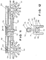
- FIG. 11 and 12 another preferred embodiment of the invention is illustrated.
- clip-like intermediate track supports can be attached to the structural framework at any of a wide variety of locations, as needed or desired, and readily adjusted to provide optimum support and contouring of the track.
- a longitudinal strut element 60 is attached at each end to rail-supporting connector elements 61.
- Each of the structural connectors 61 is provided with a rail-supporting lug 63 comprising a thin, upwardly extending stem 64 and an enlarged, generally cylindrical head 65.
- the connector elements 61 illustrated in Fig. 11 correspond generally to the connector shown in Fig. 4 except that the head portions 65 of the rail-supporting lugs are of somewhat greater length to, among other things, facilitate the joining of rail sections end to end with a portion of the head 65 projecting into each of two butted-together rail sections.
- the support element 66 includes a body portion 67 comprising a pair of spaced-apart gripping arms 68, 69 which can be generally of the same type and configuration as the pairs of gripping arms incorporated in the structural connectors 21 and 61.
- each of the gripping arms 68, 69 is formed with a transverse locking projection 70 spaced a predetermined distance from the closed base end 71 of the clip body.
- the opposite end of the clip body is open and is adapted for the crosswise reception of the strut element 60.
- the strut elements incorporated into the structural framework, including the strut 60 are formed with longitudinal grooves 72 arranged such that, when the strut 60 is forced crosswise into the body of the clip-like support 66, the grooves 72 are lockingly engaged by the projections 70, in the manner shown in Fig. 12.
- the clip-like support 66 is provided with a mounting lug 73 extending upwardly from the clip body 67, substantially in the same manner as the mounting lugs for the structural connectors 61.
- the lug 73 includes a flat upwardly projecting stem 74 integrally mounting a horizontally disposed cylindrical head portion 75.
- a strut-like connector of predetermined length. If a section of rail 62, supported by mounting lugs 63 at spaced points, needs additional support or guidance, either because of the distance between mounting lugs 63 or because of the weight of the article to be supported on the rail, a clip-like support 66 can be installed on the strut 60, in the manner shown in Fig. 11, providing intermediate support for the rail element 62.
- the gripping arms 68, 69 engage the strut with sufficient force that the support 66 is retained in its installed position by friction of the gripping action of the arms 68, 69, so that the support will remain in the position in which it is installed. That position may be manually adjusted, of course, by simply manually sliding the clip longitudinally along the strut 60, to locate the clip-like support in the most desirable location.
- the strut 60 which is engaged by the spaced-apart structural connector 61, is rotatable with respect thereto, although frictionally gripped by gripping sockets of the connectors. This enables the intermediate support to be adjusted slightly in a rotational manner, about the axis of the strut 60, so that the clip-like support 66 can automatically assume an appropriate position, even where the rail 62 has a horizontally curved configuration.
- the system of the invention enables a complex, contoured track structure to be assembled.
- the illustrated structure employs a two-rail track structure for supporting a vehicle having two or more wheels.
- Monorail and multiple rail structures are also possible with the system of the invention.
- a feature of particular advantage is the utilization of strut and connector assemblies, providing for lateral snap-in assembly of the struts and connectors to enable complex skeletal structures to be assembled, and wherein selected connector elements are provided with projecting mounting lugs for receiving and mounting, at spaced intervals, a tubular plastic (typically flexible) track element. Assembly of the basic structure proceeds in accordance with principles of the several Glickman U.S.
- the individual rails 11,12 are quickly and easily applied by either snapping the flexible rail element over the exposed ends of the rail-mounting lugs 35, or by "threading" the rail element onto the lugs in a linear fashion, advancing the end of the rail-forming tube individually over successive mounting lugs.
- Application of the rails over the mounting lugs 35 is facilitated by the divergent guide flanges 39a, which initially help to position the rail elements properly with respect to the mounting lugs and then to wedge open the throat sufficiently to allow the throat to pass over the enlarged head portions 37 of the mounting lugs.
- intermediate support of the flexible rail elements can be provided by means of clip-like supports, which can be snapped over elements of the structural framework and adjusted longitudinally therealong to any appropriate position.
- clip-like supports can be snapped over elements of the structural framework and adjusted longitudinally therealong to any appropriate position.
- This can be particularly useful where the track framework is structured for a horizontal curve, for example, because the normal span between structural connectors on the outside of the curve can be substantially greater than on the inside of the curve in such areas.
- the structure of the invention which can employ to advantage substantially continuous, flexible rail elements, enables an endless variety of railed structures to be assembled. Utilizing a kit of multiple loose parts, provided in a variety of strut lengths and connector types, a virtually endless variety of structures may be assembled for the support and guidance of wheeled vehicles along a smoothly contoured guide track arrangement. Both monorail and parallel rail structures are possible using the system of the invention.
Landscapes
- Toys (AREA)
- Supports For Pipes And Cables (AREA)
- Mutual Connection Of Rods And Tubes (AREA)
- Clamps And Clips (AREA)
Applications Claiming Priority (5)
| Application Number | Priority Date | Filing Date | Title |
|---|---|---|---|
| US08/101,422 US5421762A (en) | 1991-09-13 | 1993-08-03 | Vehicle track for construction toy system |
| US101422 | 1993-08-03 | ||
| US08/195,734 US5368514A (en) | 1991-09-13 | 1994-02-14 | Vehicle track support for construction toy system |
| US195734 | 1994-02-14 | ||
| PCT/US1994/006695 WO1995003864A1 (en) | 1993-08-03 | 1994-06-08 | Vehicle track for construction toy system |
Publications (3)
| Publication Number | Publication Date |
|---|---|
| EP0712325A1 EP0712325A1 (en) | 1996-05-22 |
| EP0712325A4 EP0712325A4 (en) | 1996-09-04 |
| EP0712325B1 true EP0712325B1 (en) | 1999-08-11 |
Family
ID=26798236
Family Applications (1)
| Application Number | Title | Priority Date | Filing Date |
|---|---|---|---|
| EP94922437A Expired - Lifetime EP0712325B1 (en) | 1993-08-03 | 1994-06-08 | Vehicle track for construction toy system |
Country Status (15)
| Country | Link |
|---|---|
| US (1) | US5368514A (cs) |
| EP (1) | EP0712325B1 (cs) |
| JP (1) | JP2928390B2 (cs) |
| CN (1) | CN1045396C (cs) |
| AT (1) | ATE183107T1 (cs) |
| AU (1) | AU674777B2 (cs) |
| BR (1) | BR9407155A (cs) |
| CA (1) | CA2166474C (cs) |
| CZ (1) | CZ31096A3 (cs) |
| DE (1) | DE69420040T2 (cs) |
| HU (1) | HUT72572A (cs) |
| IL (1) | IL110093A (cs) |
| RU (1) | RU2124915C1 (cs) |
| SK (1) | SK14896A3 (cs) |
| WO (1) | WO1995003864A1 (cs) |
Cited By (1)
| Publication number | Priority date | Publication date | Assignee | Title |
|---|---|---|---|---|
| DE10229149B4 (de) * | 2002-06-28 | 2008-05-15 | Willi Graf | Verfahren zur Steuerung einer Modellbahneinrichtung |
Families Citing this family (34)
| Publication number | Priority date | Publication date | Assignee | Title |
|---|---|---|---|---|
| US5647181A (en) * | 1994-10-11 | 1997-07-15 | Hunts; Larry David | Construction system and method for connecting rigid sheet-like panels together into doll houses, play houses, utility sheds and other structures |
| US5769681A (en) * | 1996-01-25 | 1998-06-23 | Greenwood, Sr.; Donald Lee | Open-ended toy construction system |
| US6622447B1 (en) | 1996-11-21 | 2003-09-23 | Steven Crawford Kessler | Modular hub and strut structural system |
| US6286283B1 (en) | 1996-11-21 | 2001-09-11 | Steve Kessler | Modular structural system |
| USD409679S (en) | 1998-03-18 | 1999-05-11 | Interlego Ag | Toy building element |
| US6672931B1 (en) | 2000-11-14 | 2004-01-06 | Jim Bagley | Interconnectable model construction elements |
| US6425703B1 (en) | 2001-03-01 | 2002-07-30 | Binney & Smith Inc. | Writing elements which connect together |
| US6746298B1 (en) | 2002-01-02 | 2004-06-08 | Connector Set Limited Partnership | Track structure for construction toy set |
| EP1463571B1 (en) * | 2002-01-07 | 2010-11-24 | K'NEX Limited Partnership Group | Rod and connector toy construction set |
| US6948998B2 (en) * | 2003-02-07 | 2005-09-27 | Jim Bagley | Interconnectable model construction elements |
| RU2229790C1 (ru) * | 2003-03-17 | 2004-06-10 | Полевиков Алексей Михайлович | Способ изготовления крестообразного элемента соединения трубок каркаса теплицы и крестообразный элемент соединения |
| CN1565692B (zh) * | 2003-07-09 | 2010-05-05 | 麦特尔股份有限公司 | 塑胶斜弯圆形路轨 |
| US20050191939A1 (en) * | 2004-01-23 | 2005-09-01 | Sheltman David A. | Scaffold support for toy vehicle trackset |
| EP1796804A4 (en) * | 2004-09-02 | 2009-11-11 | Dane Scarborough | TOY BOX, PROCESS AND DEVICE |
| US20090149110A1 (en) * | 2004-09-02 | 2009-06-11 | Dane Scarborough | Toy construction set |
| US20070034750A1 (en) * | 2005-08-10 | 2007-02-15 | Kns Associates, Inc. | Tubing mounting clip |
| US8651914B2 (en) * | 2006-01-27 | 2014-02-18 | Costas Sisamos | Snap-lock construction toy |
| JP2008005910A (ja) * | 2006-06-27 | 2008-01-17 | Iwaya Co Ltd | 知育玩具 |
| TWD121562S1 (zh) * | 2007-03-16 | 2008-03-01 | 輝庭企業股份有限公司 | 連結件 |
| KR101404626B1 (ko) | 2011-11-03 | 2014-06-09 | 추형욱 | 레일이동구조용 키트 |
| ITTO20130336A1 (it) * | 2013-04-24 | 2014-10-25 | Magic Production Group S A | Elemento per articoli di trastullo, sistema e procedimento relativi |
| RU2570477C2 (ru) * | 2013-12-30 | 2015-12-10 | Федеральное государственное бюджетное образовательное учреждение высшего профессионального образования Иркутский государственный университет путей сообщения (ФГБОУ ВПО ИрГУПС) | Способ макетного моделирования движения подвижного состава по рельсовому пути и конструкция для его осуществления |
| CN106267848A (zh) * | 2015-06-01 | 2017-01-04 | 林美足 | 鸠形积木 |
| DE102015015142A1 (de) * | 2015-11-25 | 2017-06-01 | Kinematics Gmbh | Baukastensystem und Verfahren zum lnformations- und/ oder Energieaustausch zwischen Modulen eines Baukastensystems |
| RU2614056C1 (ru) * | 2016-04-01 | 2017-03-22 | Акционерное Общество "Российский Концерн По Производству Электрической И Тепловой Энергии На Атомных Станциях" (Ао "Концерн Росэнергоатом") | Рельсовый путь для наклонного подъемника ядерного реактора |
| CN105903208B (zh) * | 2016-07-06 | 2019-04-23 | 骆运章 | 玩具轨道用连接件及玩具轨道 |
| RU2660962C1 (ru) * | 2017-08-08 | 2018-07-11 | Владимир Валерьевич ШУМОВСКИЙ | ИГРУШЕЧНЫЙ СТРОИТЕЛЬНЫЙ КОНСТРУКТОР "СКОРОСТНАЯ ТРАНСПОРТНАЯ СИСТЕМА ПОДВЕСНОГО ТИПА "СТРАУС" Шумовского" И КОМПЛЕКТЫ ДЕТАЛЕЙ ДЛЯ НЕГО |
| RU2661316C1 (ru) * | 2017-08-08 | 2018-07-13 | Владимир Валерьевич ШУМОВСКИЙ | ИГРУШЕЧНАЯ МАГИСТРАЛЬНАЯ ТРАССА ДЛЯ "СКОРОСТНОЙ ТРАНСПОРТНОЙ СИСТЕМЫ ПОДВЕСНОГО ТИПА "СТРАУС" Шумовского" |
| US11826668B2 (en) | 2017-09-07 | 2023-11-28 | 3Duxdesign Llc | Modeling kit including connectors and geometric shapes, and methods of making and using same |
| DE202018000191U1 (de) * | 2017-12-11 | 2018-02-22 | Meinbaukasten Gmbh | Baustein und Bausteinset für eine Murmelbahn und Murmelbahn mit einem solchen Baustein oder einem solchen Bausteinset |
| CN108635882B (zh) * | 2018-05-23 | 2020-10-23 | 闪烁天空国际有限公司 | 滑动玩具结构组件 |
| JP7212809B2 (ja) * | 2021-03-31 | 2023-01-25 | サノヤステクノサポート株式会社 | 走行路自力走行車両 |
| JP7359806B2 (ja) * | 2021-06-10 | 2023-10-11 | 矢崎総業株式会社 | プロテクタ、及び、ワイヤハーネス |
| US11654376B2 (en) * | 2021-06-15 | 2023-05-23 | Lovevery, Inc. | Count and slide ring chute |
Family Cites Families (15)
| Publication number | Priority date | Publication date | Assignee | Title |
|---|---|---|---|---|
| US2782730A (en) * | 1954-10-26 | 1957-02-26 | Lester W Frank | Toy railroad train and track |
| DK112293B (da) * | 1965-12-13 | 1968-11-25 | Lego Syst As | Skinneelement til modelbaneanlæg. |
| GB1131061A (en) * | 1966-01-19 | 1968-10-23 | Western Electric Co | Method of processing quartz |
| GB1104899A (en) * | 1966-08-13 | 1968-03-06 | Alfred Einfalt | Toy roadway layout |
| US3698130A (en) * | 1970-12-28 | 1972-10-17 | Tomy Kogyo Co | Amusement device |
| US3699711A (en) * | 1972-02-03 | 1972-10-24 | Francis T Coffey Sr | Tracked vehicle toy |
| DE3004510A1 (de) * | 1973-11-14 | 1981-08-13 | August 8000 München Mayr | Bauelementensatz fuer spielzwecke |
| DK148767C (da) * | 1979-12-20 | 1986-03-03 | Interlego Ag | Tryklaaskobling til samling af skinne- og svelleelementer ved opbygning af et banelegeme til legetoejstog |
| US4571204A (en) * | 1984-02-10 | 1986-02-18 | Wang Ta Lung | Stunt toy device |
| AR242503A1 (es) * | 1986-07-21 | 1993-04-30 | Lego As | Ferrocarril a cremallera de juguete, vehiculo motriz a vias para el mismo. |
| US5118320A (en) * | 1990-10-29 | 1992-06-02 | Miller Richard G | Roller coaster toy |
| US5238438A (en) * | 1990-12-11 | 1993-08-24 | Connector Set Limited Partnership | Construction toy and adapter |
| US5061219A (en) * | 1990-12-11 | 1991-10-29 | Magic Mold Corporation | Construction toy |
| US5199919A (en) * | 1990-12-11 | 1993-04-06 | Connector Set Limited Partnership | Construction toy system |
| US5137486A (en) * | 1990-12-11 | 1992-08-11 | Connector Set Toy Company | Multi-planar connector element for construction toy |
-
1994
- 1994-02-14 US US08/195,734 patent/US5368514A/en not_active Expired - Lifetime
- 1994-06-08 CZ CZ96310A patent/CZ31096A3/cs unknown
- 1994-06-08 EP EP94922437A patent/EP0712325B1/en not_active Expired - Lifetime
- 1994-06-08 HU HU9503808A patent/HUT72572A/hu unknown
- 1994-06-08 WO PCT/US1994/006695 patent/WO1995003864A1/en not_active Ceased
- 1994-06-08 AT AT94922437T patent/ATE183107T1/de not_active IP Right Cessation
- 1994-06-08 SK SK148-96A patent/SK14896A3/sk unknown
- 1994-06-08 RU RU96104342A patent/RU2124915C1/ru active
- 1994-06-08 DE DE69420040T patent/DE69420040T2/de not_active Expired - Lifetime
- 1994-06-08 JP JP7505809A patent/JP2928390B2/ja not_active Expired - Fee Related
- 1994-06-08 BR BR9407155A patent/BR9407155A/pt not_active Application Discontinuation
- 1994-06-08 AU AU73549/94A patent/AU674777B2/en not_active Ceased
- 1994-06-08 CN CN94192850.0A patent/CN1045396C/zh not_active Expired - Lifetime
- 1994-06-08 CA CA002166474A patent/CA2166474C/en not_active Expired - Fee Related
- 1994-06-22 IL IL110093A patent/IL110093A/xx not_active IP Right Cessation
Cited By (1)
| Publication number | Priority date | Publication date | Assignee | Title |
|---|---|---|---|---|
| DE10229149B4 (de) * | 2002-06-28 | 2008-05-15 | Willi Graf | Verfahren zur Steuerung einer Modellbahneinrichtung |
Also Published As
| Publication number | Publication date |
|---|---|
| CN1127479A (zh) | 1996-07-24 |
| RU2124915C1 (ru) | 1999-01-20 |
| WO1995003864A1 (en) | 1995-02-09 |
| CA2166474C (en) | 1997-07-29 |
| CN1045396C (zh) | 1999-10-06 |
| CZ31096A3 (en) | 1996-09-11 |
| JPH09500308A (ja) | 1997-01-14 |
| DE69420040D1 (de) | 1999-09-16 |
| AU674777B2 (en) | 1997-01-09 |
| ATE183107T1 (de) | 1999-08-15 |
| BR9407155A (pt) | 1996-09-17 |
| HUT72572A (en) | 1996-05-28 |
| IL110093A0 (en) | 1994-10-07 |
| EP0712325A1 (en) | 1996-05-22 |
| US5368514A (en) | 1994-11-29 |
| HU9503808D0 (en) | 1996-03-28 |
| IL110093A (en) | 1997-04-15 |
| AU7354994A (en) | 1995-02-28 |
| SK14896A3 (en) | 1997-02-05 |
| CA2166474A1 (en) | 1995-02-09 |
| DE69420040T2 (de) | 2000-02-03 |
| JP2928390B2 (ja) | 1999-08-03 |
| EP0712325A4 (en) | 1996-09-04 |
Similar Documents
| Publication | Publication Date | Title |
|---|---|---|
| AU674777B2 (en) | Vehicle track for construction toy system | |
| US5421762A (en) | Vehicle track for construction toy system | |
| KR0132210B1 (ko) | 조립식 완구 | |
| US6872027B2 (en) | Versatile guide rail clamp | |
| US4302865A (en) | Multi-directional canted wheel carrier with shiftable control arm for operable walls | |
| US5199919A (en) | Construction toy system | |
| US4850555A (en) | Stake and coupler for irrigation device | |
| RU96104342A (ru) | Рельсовый путь транспортного средства для системы детского конс- труктора | |
| US6398121B1 (en) | Toy train tracks | |
| JPH05162835A (ja) | モジュール式コンベア | |
| PT85366B (pt) | Linha de cremalheira de brinquedo bem como pista de deslocamento e veiculo automotor para uma linha de cremalheira de brinquedo | |
| US6533108B1 (en) | Serpentine clip | |
| US7353758B2 (en) | Track and vehicle amusement apparatus and methods | |
| US4941610A (en) | Construction piece for toy vehicle track | |
| US20180333649A1 (en) | Motorized Toy Vehicle with Improved Traction Wheels and Surface Guidance System | |
| JP7394483B2 (ja) | レール切換ユニット及びこのユニットを備えたレール構造 | |
| CZ202996A3 (en) | Chain drive for unit-built toy system | |
| US8459600B2 (en) | Trestle stabilizing device | |
| US6746298B1 (en) | Track structure for construction toy set | |
| US10035074B1 (en) | Motorized toy vehicle with improved traction wheels and surface guidance system | |
| US6546685B2 (en) | Bracket for use in securing collector flight support tracks in a wastewater treatment tank | |
| KR960703647A (ko) | 조립식 완구 시스템용 차량 트랙(vehicle track for construction toy system) | |
| JP3719571B2 (ja) | 搾乳器具用搬送装置の移動体 | |
| US20110049073A1 (en) | Runner assembly for mobile shelving | |
| EP0074958A4 (en) | TRACK AND CURSOR SUPPORT. |
Legal Events
| Date | Code | Title | Description |
|---|---|---|---|
| PUAI | Public reference made under article 153(3) epc to a published international application that has entered the european phase |
Free format text: ORIGINAL CODE: 0009012 |
|
| 17P | Request for examination filed |
Effective date: 19960119 |
|
| AK | Designated contracting states |
Kind code of ref document: A1 Designated state(s): AT BE CH DE DK ES FR GB GR IE IT LI LU MC NL PT SE |
|
| A4 | Supplementary search report drawn up and despatched |
Effective date: 19960722 |
|
| AK | Designated contracting states |
Kind code of ref document: A4 Designated state(s): AT BE CH DE DK ES FR GB GR IE IT LI LU MC NL PT SE |
|
| RHK1 | Main classification (correction) |
Ipc: A63H 19/30 |
|
| 17Q | First examination report despatched |
Effective date: 19970722 |
|
| RAP1 | Party data changed (applicant data changed or rights of an application transferred) |
Owner name: CONNECTOR SET LIMITED PARTNERSHIP |
|
| GRAG | Despatch of communication of intention to grant |
Free format text: ORIGINAL CODE: EPIDOS AGRA |
|
| GRAG | Despatch of communication of intention to grant |
Free format text: ORIGINAL CODE: EPIDOS AGRA |
|
| GRAG | Despatch of communication of intention to grant |
Free format text: ORIGINAL CODE: EPIDOS AGRA |
|
| GRAH | Despatch of communication of intention to grant a patent |
Free format text: ORIGINAL CODE: EPIDOS IGRA |
|
| GRAH | Despatch of communication of intention to grant a patent |
Free format text: ORIGINAL CODE: EPIDOS IGRA |
|
| GRAA | (expected) grant |
Free format text: ORIGINAL CODE: 0009210 |
|
| AK | Designated contracting states |
Kind code of ref document: B1 Designated state(s): AT BE CH DE DK ES FR GB GR IE IT LI LU MC NL PT SE |
|
| PG25 | Lapsed in a contracting state [announced via postgrant information from national office to epo] |
Ref country code: SE Free format text: THE PATENT HAS BEEN ANNULLED BY A DECISION OF A NATIONAL AUTHORITY Effective date: 19990811 Ref country code: NL Free format text: LAPSE BECAUSE OF FAILURE TO SUBMIT A TRANSLATION OF THE DESCRIPTION OR TO PAY THE FEE WITHIN THE PRESCRIBED TIME-LIMIT Effective date: 19990811 Ref country code: LI Free format text: LAPSE BECAUSE OF FAILURE TO SUBMIT A TRANSLATION OF THE DESCRIPTION OR TO PAY THE FEE WITHIN THE PRESCRIBED TIME-LIMIT Effective date: 19990811 Ref country code: IT Free format text: LAPSE BECAUSE OF FAILURE TO SUBMIT A TRANSLATION OF THE DESCRIPTION OR TO PAY THE FEE WITHIN THE PRE;WARNING: LAPSES OF ITALIAN PATENTS WITH EFFECTIVE DATE BEFORE 2007 MAY HAVE OCCURRED AT ANY TIME BEFORE 2007. THE CORRECT EFFECTIVE DATE MAY BE DIFFERENT FROM THE ONE RECORDED.SCRIBED TIME-LIMIT Effective date: 19990811 Ref country code: GR Free format text: LAPSE BECAUSE OF NON-PAYMENT OF DUE FEES Effective date: 19990811 Ref country code: ES Free format text: THE PATENT HAS BEEN ANNULLED BY A DECISION OF A NATIONAL AUTHORITY Effective date: 19990811 Ref country code: CH Free format text: LAPSE BECAUSE OF FAILURE TO SUBMIT A TRANSLATION OF THE DESCRIPTION OR TO PAY THE FEE WITHIN THE PRESCRIBED TIME-LIMIT Effective date: 19990811 Ref country code: BE Free format text: LAPSE BECAUSE OF FAILURE TO SUBMIT A TRANSLATION OF THE DESCRIPTION OR TO PAY THE FEE WITHIN THE PRESCRIBED TIME-LIMIT Effective date: 19990811 Ref country code: AT Free format text: LAPSE BECAUSE OF FAILURE TO SUBMIT A TRANSLATION OF THE DESCRIPTION OR TO PAY THE FEE WITHIN THE PRESCRIBED TIME-LIMIT Effective date: 19990811 |
|
| REF | Corresponds to: |
Ref document number: 183107 Country of ref document: AT Date of ref document: 19990815 Kind code of ref document: T |
|
| REG | Reference to a national code |
Ref country code: CH Ref legal event code: EP |
|
| REF | Corresponds to: |
Ref document number: 69420040 Country of ref document: DE Date of ref document: 19990916 |
|
| REG | Reference to a national code |
Ref country code: IE Ref legal event code: FG4D |
|
| PG25 | Lapsed in a contracting state [announced via postgrant information from national office to epo] |
Ref country code: PT Free format text: LAPSE BECAUSE OF FAILURE TO SUBMIT A TRANSLATION OF THE DESCRIPTION OR TO PAY THE FEE WITHIN THE PRESCRIBED TIME-LIMIT Effective date: 19991111 Ref country code: DK Free format text: LAPSE BECAUSE OF FAILURE TO SUBMIT A TRANSLATION OF THE DESCRIPTION OR TO PAY THE FEE WITHIN THE PRESCRIBED TIME-LIMIT Effective date: 19991111 |
|
| ET | Fr: translation filed | ||
| NLV1 | Nl: lapsed or annulled due to failure to fulfill the requirements of art. 29p and 29m of the patents act | ||
| REG | Reference to a national code |
Ref country code: CH Ref legal event code: PL |
|
| PG25 | Lapsed in a contracting state [announced via postgrant information from national office to epo] |
Ref country code: LU Free format text: LAPSE BECAUSE OF NON-PAYMENT OF DUE FEES Effective date: 20000608 Ref country code: IE Free format text: LAPSE BECAUSE OF NON-PAYMENT OF DUE FEES Effective date: 20000608 |
|
| PLBE | No opposition filed within time limit |
Free format text: ORIGINAL CODE: 0009261 |
|
| STAA | Information on the status of an ep patent application or granted ep patent |
Free format text: STATUS: NO OPPOSITION FILED WITHIN TIME LIMIT |
|
| PG25 | Lapsed in a contracting state [announced via postgrant information from national office to epo] |
Ref country code: MC Free format text: THE PATENT HAS BEEN ANNULLED BY A DECISION OF A NATIONAL AUTHORITY Effective date: 20000630 |
|
| 26N | No opposition filed | ||
| REG | Reference to a national code |
Ref country code: IE Ref legal event code: MM4A |
|
| REG | Reference to a national code |
Ref country code: GB Ref legal event code: IF02 |
|
| REG | Reference to a national code |
Ref country code: FR Ref legal event code: TP Ref country code: FR Ref legal event code: CD |
|
| PGFP | Annual fee paid to national office [announced via postgrant information from national office to epo] |
Ref country code: GB Payment date: 20130514 Year of fee payment: 20 Ref country code: DE Payment date: 20130630 Year of fee payment: 20 |
|
| PGFP | Annual fee paid to national office [announced via postgrant information from national office to epo] |
Ref country code: FR Payment date: 20130627 Year of fee payment: 20 |
|
| REG | Reference to a national code |
Ref country code: DE Ref legal event code: R071 Ref document number: 69420040 Country of ref document: DE |
|
| REG | Reference to a national code |
Ref country code: DE Ref legal event code: R071 Ref document number: 69420040 Country of ref document: DE |
|
| REG | Reference to a national code |
Ref country code: GB Ref legal event code: PE20 Expiry date: 20140607 |
|
| PG25 | Lapsed in a contracting state [announced via postgrant information from national office to epo] |
Ref country code: GB Free format text: LAPSE BECAUSE OF EXPIRATION OF PROTECTION Effective date: 20140607 |
|
| PG25 | Lapsed in a contracting state [announced via postgrant information from national office to epo] |
Ref country code: DE Free format text: LAPSE BECAUSE OF EXPIRATION OF PROTECTION Effective date: 20140611 |