EP0712357B1 - Durch spritzgiessen geformtes kunststoffrad für fahrrad - Google Patents
Durch spritzgiessen geformtes kunststoffrad für fahrrad Download PDFInfo
- Publication number
- EP0712357B1 EP0712357B1 EP94920806A EP94920806A EP0712357B1 EP 0712357 B1 EP0712357 B1 EP 0712357B1 EP 94920806 A EP94920806 A EP 94920806A EP 94920806 A EP94920806 A EP 94920806A EP 0712357 B1 EP0712357 B1 EP 0712357B1
- Authority
- EP
- European Patent Office
- Prior art keywords
- rim
- wheel
- bicycle wheel
- mandrel
- annulus
- Prior art date
- Legal status (The legal status is an assumption and is not a legal conclusion. Google has not performed a legal analysis and makes no representation as to the accuracy of the status listed.)
- Expired - Lifetime
Links
- 238000002347 injection Methods 0.000 title claims description 6
- 239000007924 injection Substances 0.000 title claims description 6
- 239000002991 molded plastic Substances 0.000 title description 7
- 238000001746 injection moulding Methods 0.000 claims abstract description 18
- 239000004033 plastic Substances 0.000 claims abstract description 14
- 229920003023 plastic Polymers 0.000 claims abstract description 14
- 230000002093 peripheral effect Effects 0.000 claims abstract description 7
- 229910052751 metal Inorganic materials 0.000 claims description 22
- 239000002184 metal Substances 0.000 claims description 22
- 238000000034 method Methods 0.000 claims description 13
- 230000005496 eutectics Effects 0.000 claims description 9
- 238000000465 moulding Methods 0.000 claims description 9
- 239000007787 solid Substances 0.000 claims description 6
- 238000004519 manufacturing process Methods 0.000 claims description 5
- 229920002430 Fibre-reinforced plastic Polymers 0.000 claims description 3
- 239000011151 fibre-reinforced plastic Substances 0.000 claims description 3
- 239000007788 liquid Substances 0.000 claims description 3
- 239000000463 material Substances 0.000 claims description 3
- 230000015572 biosynthetic process Effects 0.000 abstract description 3
- 229920005989 resin Polymers 0.000 description 8
- 239000011347 resin Substances 0.000 description 8
- 239000000835 fiber Substances 0.000 description 7
- OKTJSMMVPCPJKN-UHFFFAOYSA-N Carbon Chemical compound [C] OKTJSMMVPCPJKN-UHFFFAOYSA-N 0.000 description 5
- 239000000853 adhesive Substances 0.000 description 5
- 230000001070 adhesive effect Effects 0.000 description 5
- 229910002804 graphite Inorganic materials 0.000 description 4
- 239000010439 graphite Substances 0.000 description 4
- 238000010276 construction Methods 0.000 description 3
- -1 e.g. Polymers 0.000 description 3
- 238000001125 extrusion Methods 0.000 description 3
- 239000000155 melt Substances 0.000 description 3
- FYYHWMGAXLPEAU-UHFFFAOYSA-N Magnesium Chemical compound [Mg] FYYHWMGAXLPEAU-UHFFFAOYSA-N 0.000 description 2
- 239000004677 Nylon Substances 0.000 description 2
- 239000004734 Polyphenylene sulfide Substances 0.000 description 2
- 229910045601 alloy Inorganic materials 0.000 description 2
- 239000000956 alloy Substances 0.000 description 2
- 229910052782 aluminium Inorganic materials 0.000 description 2
- XAGFODPZIPBFFR-UHFFFAOYSA-N aluminium Chemical compound [Al] XAGFODPZIPBFFR-UHFFFAOYSA-N 0.000 description 2
- 229920001971 elastomer Polymers 0.000 description 2
- 239000003822 epoxy resin Substances 0.000 description 2
- 239000011152 fibreglass Substances 0.000 description 2
- LNEPOXFFQSENCJ-UHFFFAOYSA-N haloperidol Chemical compound C1CC(O)(C=2C=CC(Cl)=CC=2)CCN1CCCC(=O)C1=CC=C(F)C=C1 LNEPOXFFQSENCJ-UHFFFAOYSA-N 0.000 description 2
- 229910052749 magnesium Inorganic materials 0.000 description 2
- 239000011777 magnesium Substances 0.000 description 2
- 229920001778 nylon Polymers 0.000 description 2
- 239000002984 plastic foam Substances 0.000 description 2
- 229920000647 polyepoxide Polymers 0.000 description 2
- 229920000642 polymer Polymers 0.000 description 2
- 229920000069 polyphenylene sulfide Polymers 0.000 description 2
- 239000005060 rubber Substances 0.000 description 2
- 229920005992 thermoplastic resin Polymers 0.000 description 2
- 238000003466 welding Methods 0.000 description 2
- VYZAMTAEIAYCRO-UHFFFAOYSA-N Chromium Chemical compound [Cr] VYZAMTAEIAYCRO-UHFFFAOYSA-N 0.000 description 1
- 229910001209 Low-carbon steel Inorganic materials 0.000 description 1
- 239000004952 Polyamide Substances 0.000 description 1
- 239000004697 Polyetherimide Substances 0.000 description 1
- 239000004698 Polyethylene Substances 0.000 description 1
- 239000004372 Polyvinyl alcohol Substances 0.000 description 1
- 229910000831 Steel Inorganic materials 0.000 description 1
- 229920006243 acrylic copolymer Polymers 0.000 description 1
- 229910052799 carbon Inorganic materials 0.000 description 1
- 238000004090 dissolution Methods 0.000 description 1
- 230000002708 enhancing effect Effects 0.000 description 1
- 238000010135 hand fabrication Methods 0.000 description 1
- 238000009787 hand lay-up Methods 0.000 description 1
- 238000003780 insertion Methods 0.000 description 1
- 230000037431 insertion Effects 0.000 description 1
- 230000008018 melting Effects 0.000 description 1
- 238000002844 melting Methods 0.000 description 1
- 150000002739 metals Chemical class 0.000 description 1
- 239000012764 mineral filler Substances 0.000 description 1
- 239000000203 mixture Substances 0.000 description 1
- 229920002647 polyamide Polymers 0.000 description 1
- 229920000728 polyester Polymers 0.000 description 1
- 229920001601 polyetherimide Polymers 0.000 description 1
- 229920000573 polyethylene Polymers 0.000 description 1
- 229920002635 polyurethane Polymers 0.000 description 1
- 239000004814 polyurethane Substances 0.000 description 1
- 229920002451 polyvinyl alcohol Polymers 0.000 description 1
- 239000002990 reinforced plastic Substances 0.000 description 1
- 239000012783 reinforcing fiber Substances 0.000 description 1
- 230000000717 retained effect Effects 0.000 description 1
- 238000007711 solidification Methods 0.000 description 1
- 230000008023 solidification Effects 0.000 description 1
- 239000002904 solvent Substances 0.000 description 1
- 229910001220 stainless steel Inorganic materials 0.000 description 1
- 239000010935 stainless steel Substances 0.000 description 1
- 239000010959 steel Substances 0.000 description 1
- 229920001169 thermoplastic Polymers 0.000 description 1
- 229920001187 thermosetting polymer Polymers 0.000 description 1
- 239000004634 thermosetting polymer Substances 0.000 description 1
- XLYOFNOQVPJJNP-UHFFFAOYSA-N water Substances O XLYOFNOQVPJJNP-UHFFFAOYSA-N 0.000 description 1
- 229920003169 water-soluble polymer Polymers 0.000 description 1
Images


Classifications
-
- B—PERFORMING OPERATIONS; TRANSPORTING
- B29—WORKING OF PLASTICS; WORKING OF SUBSTANCES IN A PLASTIC STATE IN GENERAL
- B29C—SHAPING OR JOINING OF PLASTICS; SHAPING OF MATERIAL IN A PLASTIC STATE, NOT OTHERWISE PROVIDED FOR; AFTER-TREATMENT OF THE SHAPED PRODUCTS, e.g. REPAIRING
- B29C45/00—Injection moulding, i.e. forcing the required volume of moulding material through a nozzle into a closed mould; Apparatus therefor
- B29C45/14—Injection moulding, i.e. forcing the required volume of moulding material through a nozzle into a closed mould; Apparatus therefor incorporating preformed parts or layers, e.g. injection moulding around inserts or for coating articles
-
- B—PERFORMING OPERATIONS; TRANSPORTING
- B29—WORKING OF PLASTICS; WORKING OF SUBSTANCES IN A PLASTIC STATE IN GENERAL
- B29C—SHAPING OR JOINING OF PLASTICS; SHAPING OF MATERIAL IN A PLASTIC STATE, NOT OTHERWISE PROVIDED FOR; AFTER-TREATMENT OF THE SHAPED PRODUCTS, e.g. REPAIRING
- B29C33/00—Moulds or cores; Details thereof or accessories therefor
- B29C33/44—Moulds or cores; Details thereof or accessories therefor with means for, or specially constructed to facilitate, the removal of articles, e.g. of undercut articles
- B29C33/52—Moulds or cores; Details thereof or accessories therefor with means for, or specially constructed to facilitate, the removal of articles, e.g. of undercut articles soluble or fusible
-
- B—PERFORMING OPERATIONS; TRANSPORTING
- B29—WORKING OF PLASTICS; WORKING OF SUBSTANCES IN A PLASTIC STATE IN GENERAL
- B29C—SHAPING OR JOINING OF PLASTICS; SHAPING OF MATERIAL IN A PLASTIC STATE, NOT OTHERWISE PROVIDED FOR; AFTER-TREATMENT OF THE SHAPED PRODUCTS, e.g. REPAIRING
- B29C45/00—Injection moulding, i.e. forcing the required volume of moulding material through a nozzle into a closed mould; Apparatus therefor
- B29C45/17—Component parts, details or accessories; Auxiliary operations
- B29C45/40—Removing or ejecting moulded articles
- B29C45/44—Removing or ejecting moulded articles for undercut articles
- B29C45/4457—Removing or ejecting moulded articles for undercut articles using fusible, soluble or destructible cores
-
- B—PERFORMING OPERATIONS; TRANSPORTING
- B29—WORKING OF PLASTICS; WORKING OF SUBSTANCES IN A PLASTIC STATE IN GENERAL
- B29C—SHAPING OR JOINING OF PLASTICS; SHAPING OF MATERIAL IN A PLASTIC STATE, NOT OTHERWISE PROVIDED FOR; AFTER-TREATMENT OF THE SHAPED PRODUCTS, e.g. REPAIRING
- B29C70/00—Shaping composites, i.e. plastics material comprising reinforcements, fillers or preformed parts, e.g. inserts
- B29C70/68—Shaping composites, i.e. plastics material comprising reinforcements, fillers or preformed parts, e.g. inserts by incorporating or moulding on preformed parts, e.g. inserts or layers, e.g. foam blocks
- B29C70/74—Moulding material on a relatively small portion of the preformed part, e.g. outsert moulding
- B29C70/742—Forming a hollow body around the preformed part
-
- B—PERFORMING OPERATIONS; TRANSPORTING
- B60—VEHICLES IN GENERAL
- B60B—VEHICLE WHEELS; CASTORS; AXLES FOR WHEELS OR CASTORS; INCREASING WHEEL ADHESION
- B60B1/00—Spoked wheels; Spokes thereof
- B60B1/003—Spoked wheels; Spokes thereof specially adapted for bicycles
-
- B—PERFORMING OPERATIONS; TRANSPORTING
- B60—VEHICLES IN GENERAL
- B60B—VEHICLE WHEELS; CASTORS; AXLES FOR WHEELS OR CASTORS; INCREASING WHEEL ADHESION
- B60B5/00—Wheels, spokes, disc bodies, rims, hubs, wholly or predominantly made of non-metallic material
- B60B5/02—Wheels, spokes, disc bodies, rims, hubs, wholly or predominantly made of non-metallic material made of synthetic material
-
- B—PERFORMING OPERATIONS; TRANSPORTING
- B29—WORKING OF PLASTICS; WORKING OF SUBSTANCES IN A PLASTIC STATE IN GENERAL
- B29L—INDEXING SCHEME ASSOCIATED WITH SUBCLASS B29C, RELATING TO PARTICULAR ARTICLES
- B29L2031/00—Other particular articles
- B29L2031/30—Vehicles, e.g. ships or aircraft, or body parts thereof
- B29L2031/3091—Bicycles
-
- B—PERFORMING OPERATIONS; TRANSPORTING
- B29—WORKING OF PLASTICS; WORKING OF SUBSTANCES IN A PLASTIC STATE IN GENERAL
- B29L—INDEXING SCHEME ASSOCIATED WITH SUBCLASS B29C, RELATING TO PARTICULAR ARTICLES
- B29L2031/00—Other particular articles
- B29L2031/32—Wheels, pinions, pulleys, castors or rollers, Rims
Definitions
- This invention relates a molded plastic wheel and, in particular, to a hollow-form wheel with an independently formed rim for use on bicycles.
- Plastic wheels for bicycles and other applications have been provided by a variety of molding techniques.
- a large number of prior patents disclose wheels which are made by injection molding, but which are not hollow-form. Instead, these wheels have solid ribs or spokes which extend between a central hub and outer rim. Examples of such patents are U. S. Patents 4,508,392 and 4,793,659.
- Other attempts to provide a molded plastic wheel suitable for use on bicycles are described in U. S. Patents 3,862,779 and 4,818,034.
- a hollow-form wheel is assembled from split, mirror image halves and the assembly is retained by suitable fasteners or studs. While this approach can provide a hollow form wheel, it compromises the strength of the wheel and requires substantial manual assembly.
- Molded plastic bicycle wheels have been marketed with limited success. These wheels are three-spoke plastic wheels which are made by applying multiple layers of resin impregnated graphite fiber onto a plastic foam or rubber mandrel that is placed in a mold and heated to cure the resin. The plastic foam mandrel remains in the wheel. The rubber mandrel is extracted from the hub and annulus areas of the wheel and a separate rim and a separate hub are bonded to the wheel by secondary bonding.
- This invention comprises a hollow-form wheel formed by injection molding of plastic to which is bonded an independently formed rim.
- the wheel has an integral, central sleeve to receive a wheel hub assembly, at least three, hollow-form, integral spokes that are symmetrically located at equal angular spacings about the hub, and an integrally formed outer annulus which receives an independently formed rim suitable for mounting of a conventional tire.
- the rim can be molded of plastics which are different from those used for the wheel, or can be formed of metal.
- the rim can be bonded to the outer annulus of the wheel with secondary bonding, or the rim can be placed in the mold used to form the wheel and the annulus can be formed and bonded to the rim during injection molding of the wheel.
- the molded bicycle wheel 10 of the invention is shown as having a central sleeve 12 that, preferably, has a plurality of axial grooves 14 (see FIGURE 13) to receive a conventional bearing hub assembly (not shown).
- the sleeve 12 is integrally formed with the remainder of the wheel which comprises a plurality of spokes 16, preferably three, which extend radially outwardly from a hub 18 to an annulus 20.
- An annular rim 21 is bonded to the outer annulus 20 and has sidewalls 24 to receive a conventional tire.
- a greater number of spokes can be provided, if desired, for optimum balance of strength and stiffness with minimum weight.
- the spokes 16 are ellipsoidal in shape, preferably with an elongated ellipsoidal contour as apparent in the sectional views.
- the spokes taper from a minimum thickness at the annulus 20 to the hub 18, which is of greater thickness.
- the spokes have a tapered thickness for approximately 2/3 their length along a curvilinear arc, following a large diameter radius of curvature. Straight tapers over greater or slightly lesser lengths can be provided, if desired. provided that the spokes taper smoothly in thickness from the hub 18 to the annulus 21 over a major portion of their length.
- the tapered thickness of the spokes increases the strength and lateral stiffness of the wheel, and provides an appearance of a more substantial construction then has a wheel of the uniform thickness.
- a wheel having spokes of tapered thickness as shown in FIGURE 2, has 30 to 40 percent greater lateral stiffness than a wheel having spokes of uniform thickness.
- the two wheels are substantially the same weight, as the tapering of the spokes, as illustrated, adds less than one percent to the weight of the wheel.
- the spokes 16 and the annulus 20 are joined with fillets 19 having smooth radii.
- the spokes are formed with edges 30 and 32 which have radii of curvature at centers that are located outside the circumference of the rim. This shape maximizes the aerodynamic and strength properties of the wheel.
- the wheel is injection molded of thermoplastic resins, e.g., Nylon, polyphenylene sulfide, polyether imide, polyesters, polyurethane, etc., or of thermoset resins, e.g., epoxy resins.
- the resins are reinforced with long chopped fibers, such as fiberglass or, preferably graphite fibers, which are added in amounts from 10 to about 60 weight percent.
- the fibers which are very useful have lengths from about 0.1 to about 0.75 inch.
- the preferred resin for most applications is Nylon reinforced with graphite fibers at a concentration about 25 weight percent.
- FIGURES 3-6 are enlarged for greater clarity, and the thicknesses of the sidewalls is increased for illustration purposes.
- the minor axis of each section increases from FIGURE 4 to FIGURE 5.
- the minor axis 4 of the elliptical section shown in FIGURE 4 is less than minor axis 5 of FIGURE 5, which is less than the minor axis 6 of FIGURE 6.
- spokes 16 have a ratio of width to thickness greater than 1.0 throughout their entire length.
- the wall thickness of the wheel is sufficient to provide a performance which is equal or greater than that of a conventional steel-spoke bicycle wheel.
- a wall thickness from 0.075 to 0.125 inch, preferably about 0.09 inch provides the necessary stiffness, strength and flexibility to equal or exceed the performance of a conventional steel-spoked bicycle wheel.
- the annulus 20 has a streamlined shape with a hemi-ellipsoidal contour.
- the annulus 20 of the wheel is entirely enclosed, with a wide base wall 26 that provides a surface for bonding to the base wall 25 of the rim 21.
- the rim 21 is in the shape of an annular channel which, preferably has parallel sidewalls 24 which support coextensive inwardly directed annular lips 28, thereby forming a conventional rim to receive a conventional bicycle tire.
- the rim can be formed of metal, e.g., aluminum, magnesium, or their alloys, stainless steel, or chrome plated mild steel and is bonded to the base wall 26 of the annulus 20.
- the bonding can be secondary bonding with a suitable permanent adhesive or resin.
- the rim 21 can be inserted into the mold cavity in the manner described with reference to FIGURES 8-10, and the rim is then bonded to the base wall 26 of the annulus during its formation in the injection molding of the wheel.
- the rim 27 has side walls 24 with inwardly directed lips 28, as previously described.
- the rim also has a concave inner wall 29 and a flat bottom wall 31.
- the undersurface of the bottom wall 31 is preferably knurled to provide a roughened surface to enhance bonding to the molded plastic wheel.
- the bottom wall of the rim has a triangular channel 33 which is centered in the middle of the rim 27, dividing the hollow interior of the rim into two annular chambers 35 and 37, located at each side of the rim.
- the rim 27 is formed by conventional extrusion fabrication as a straight extrusion which is rolled to the proper diameter. To complete the rim, its ends are joined and the joint is secured in a conventional manner such as bonding with adhesives, welding, or with suitable fasteners, e.g., pins or rivets.
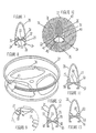
- the rim 27 is the form of a rolled extrusion is snapped over the eutectic metal mandrel 39 used for the injection molding of the wheel.
- the mandrel is simplified for illustration purposes and appears to have square shoulders.
- the cross sections of the annulus, the spokes and hub are the elliptical and hemi-elliptical as shown by the interiors of the wheel cross sections which appear in FIGURES 3-6 and 15.
- the mandrel 39 has a raised peripheral rim 41 along its midline, and rim 41 has a triangular cross section conforming to the triangular channel 33 in rim 27, thereby centering the rim on the mandrel.
- the rib 41 on the outer periphery of the mandrel 39 is not shown in FIGURE 8, however, it appears in the cross-sectional view of the mandrel in FIGURE 10.
- pins 43 and bores 87 which receive the pins are shown in an enlarged view.
- the rim fasteners pins 43 are inserted in bores 87 and secured by adhesives or welding to form a rim which is locked to the mandrel 39.
- FIGURE 10 is a sectional view of the rim and annulus cavity 45 of the injection mold 47 used to form the wheel.
- a two-piece mold is used with mold halves 47 and 74 which engage at parting plane 76.
- the assembly of the mandrel 39 and rim 27 are shown in place in the mold cavity 45, prior to injection molding.
- the assembly of the rim and mandrel is centered in the cavity by the side walls 49 of the cavity which receive the side walls 24 of the rim.
- the knurled bottom wall 31 of the rim 27 completes the cavity 51 for forming of the wheel annulus 20. Since the rim 27 is centered on the mandrel 39, the rim thereby centers and supports the mandrel 39 by its outer edges in the mold cavity during injection molding of the wheel about the mandrel.
- the wheel After its formation, the wheel is heated to melt the mandrel, and apertures 53 in the inner wall 29 (see FIGURES 8 and 18) of the rim 27 provide drainage for the molten mandrel.
- the rim 57 has a pair of grooves 59 and 61 in its base wall 63, and each of the outer walls 15 and 17 of the annulus 20 are received in grooves 59 and 61 to interlock the rim to the wheel.
- the rim has a slightly wider profile than the annulus with internal flanges 64 that extend into the annulus to provide an expanded area for bonding between the rim and wheel.
- FIGURE 12 illustrates another embodiment in which the rim 65 has a pair of ribs 67 and 69 on its base wall 71.
- the annulus 20 has inwardly formed lips 73 and 75 on its side walls 15 and 17 with annular grooves 77 and 79 which receive the ribs 67 and 69.
- the grooves and lips can be dovetailed if desired for enhancing the strength of the joint.
- the rim and wheel are separately formed, the rim can be bonded to the annulus with a permanent adhesive. between the base wall 71 and lips 73 and 75.
- FIGURE 13 Another embodiment is shown in FIGURE 13, in which the rim 81 has its side walls extended a slight distance to form grooves 89 along its opposite sides.
- the side walls 83 of the annulus are formed with interlocking shoulders 85 within the grooves 89.
- the rim can be centered on the mandrel and the wheel bonded to the rim during molding, or rim can be bonded to the wheel by adhesives, etc. after molding the wheel.
- the use of an independently formed rim permits selection of a different material for the rim.
- the rim can be formed of steel, aluminum, or magnesium or their alloys.
- the rim can be formed of a resin and/or reinforcing fiber different from that used for the wheel.
- the wheel can be molded of epoxy resins, polyamide, polyethylene terephthlate, polyphenylene sulfide, etc., and can be reinforced with continuous fibers of carbon, graphite or fiberglass.
- the rims can be formed of fiber reinforced plastics using hand lay up methods to achieve highly oriented fibers. These rims can then be secondarily bonded to the wheel, or can be placed in the mold, in the same manner as described with regard to FIGURES 8-10.
- FIGURE 14 is an enlarged sectional view through the wheel and annulus at the inflation stem area.
- the annulus has a necked section of reduced major width which provides clearance for a conventional air delivery nozzle.
- the through aperture 36 is aligned with a second through aperture 38 that extends transversely through the base wall 26 of the annulus and base wall 25 of the rim 21, thereby providing for passage or insertion of the conventional inflation stem of a balloon tire.
- the central sleeve 12 of the hub is shown in plan views in FIGURES 16 and 17. As illustrated in FIGURE 15, the central hub area 18 has an outer edge 19 that is hemi-elliptical in shape and is also of hollow form.
- the hub area 18 has a centrally located, integrally formed sleeve 12 which has a plurality of apertures 17 which communicate with the interior of each of the spokes 16. These apertures permitting draining of the molten eutectic metal mandrel after molding of the wheel and permit support of the mandrel in the mold cavity.
- the sleeve 12 has a plurality of axial slots 14 on its inside wall; see also FIGURES 16 and 17.
- the slots 14 receive axial ribs which are located on the outer cylindrical casing of the standard metal hub and bearing assembly which fits into the integral plastic sleeve 12 of the wheel 10.
- the integral plastic hub 12 is shown with a plurality of lobed-shaped cavities 14a which receive lobes that are located on the outer wall of the casing of a standard metal hub and bearing assembly. As shown in FIGURE 17, the lobes or slots extend along the inside wall of the hub 12.
- the base wall 26 of the annular peripheral rim 24 of the tire is formed with a plurality of apertures 53 that are spaced apart at equal angular increment about the periphery of the wheel.
- the shape of the apertures is not critical; circular holes, or elongated slots as shown in FIGURE 18 , can be used.
- the apertures minimize wheel weight without significantly comprising the rigidity and strength of the wheel. Also, these apertures permit draining of the molten metal formed when the metal mandrel is melted, as described hereinafter.
- the wheel of the invention is formed by injection molding.
- the hollow form structure of the wheel is achieved with injection molding of a resin about a preformed mandrel.
- the mandrel should be liquefiable, i.e, be capable of a change in state from solid to liquid, and in the solid state should be stable to the molding conditions of temperature and pressure. It should also be capable of the change in physical state from solid to liquid under conditions which do not affect the molded products.
- One method is to use a mandrel which is formed of a eutectic metal having a melt point which is slightly below the melt temperature of the thermoplastic polymer.
- eutectic metals for this purpose are available from Electrovert, 655 Main St., East Greenwich, RI.
- the mandrel is formed with very close tolerances to the interior dimensions of the injection mold cavity so that the hollow form wheel that is produced will have uniform wall thickness throughout, with the thickness as previously mentioned.
- a mandrel which will dissolve in a solvent that is innocuous to the molded product, e.g., a mandrel formed of a water soluble polymer such as polyvinyl alcohol or acrylic copolymers, which can include a mineral filler for dimensional stability under the injection molding conditions.
- a solvent that is innocuous to the molded product e.g., a mandrel formed of a water soluble polymer such as polyvinyl alcohol or acrylic copolymers, which can include a mineral filler for dimensional stability under the injection molding conditions.
- the injection molding is conventional in procedure.
- the polymer is injected at a temperature above its melt point and flows into the mold cavity about the mandrel.
- the temperature of the mold is controlled in a conventional manner to obtain solidification of the polymer, which is ejected from the mold, still containing the metal mandrel.
- a typical cycle time for the injection molding is from 40 to about 75 seconds for thermoplastic resins,and from 2 to about 6 minutes for thermosetting resins.
- the molded wheel and eutectic metal mandrel are then placed in an oil bath which is maintained at the melt temperature of the eutectic metal used for the mandrel.
- the oil bath heats the metal, melting it and the molten metal drains from the finished wheel through the apertures 53 located about the annular rim 21 of the wheel and from the apertures 17 in the hub sleeve 12, with the result that an entirely integral molded plastic wheel is obtained having a very uniform wall thickness, weight and strength.
- the same procedure is followed with the soluble mandrel.
- the molded wheel and water-soluble mandrel are placed in a water bath which can be heated to a moderate temperature, e.g., from 100 to 200 degrees F. to hasten the rate of dissolution of the mandrel.
- the wheel is then removed, drained, rinsed and dried to obtain the finished product as a one-piece, hollow-form wheel.
- the wheel is formed with a high degree of balance, requiring little work to provide complete balance of wheel.
- the molten eutectic metal accumulates as a settled layer within the oil bath from where it can be drained for reuse in fabrication of the mandrels.
Landscapes
- Engineering & Computer Science (AREA)
- Mechanical Engineering (AREA)
- Chemical & Material Sciences (AREA)
- Manufacturing & Machinery (AREA)
- Materials Engineering (AREA)
- Composite Materials (AREA)
- Injection Moulding Of Plastics Or The Like (AREA)
Claims (13)
- Ein eine hohle Form aufweisendes Fahrrad-Rad (10) mit einer mittigen Nabe (18) und mit eine hohle Form besitzenden Speichen (16) und einem integral ausgebildeten Umfangsring (20), wobei das Rad vollständig durch Spritzguss eines faserverstärkten Plastikmaterials geformt ist, und wobei das Rad eine ringförmige Felge (21) aufweist, und zwar auf dem erwähnten Ring (20), dadurch gekennzeichnet, dass die mittige Nabe (18) eine erste Dicke besitzt, dass deren integral ausgeformter Umfangsring (20) eine zweite kleinere Dicke besitzt, und wobei die eine hohle Form besitzenden integral geformten Speichen (16) sich in ihrer Dicke von der ersten zu der zweiten Dicke entlang eines Hauptteils ihrer Länge verjüngen, und wobei die ringförmige Felge (21) unabhängig von dem Ring (20) geformt und mit diesem verbunden wird.
- Fahrrad-Rad nach Anspruch 1 mit mindestens drei eine hohle Form besitzenden Speichen (16) mit einem Breiten- zu Dickenverhältnis größer als 1, und zwar integral mit der erwähnten Nabe (18) und dem Ring (21) und symmetrisch angeordnet darum herum mit gleichen Winkelbeabstandungen.
- Fahrrad-Rad nach Anspruch 2, wobei die Speichen (16) ellipsoidförmige Querschnitte besitzen.
- Fahrrad-Rad nach Anspruch 2, wobei die ringförmige Felge (21) Mittel besitzt, um ihre Mittellinienebene mit einem Dorn zu indizieren, der zur Formung des Fahrrad-Rades verwendet wird.
- Fahrrad-Rad nach Anspruch 4, wobei die Indiziermittel einen Kanal in einer Basiswand (25) der Felge (21) aufweisen, der die Mittellinienebene der Felge auskleidet.
- Fahrrad-Rad nach Anspruch 5, wobei der Kanal einen dreieckigen Querschnitt besitzt.
- Fahrrad-Rad nach Anspruch 1, wobei die Mittelnabe (18) eine Mittelhülse (12) aufweist mit einem Innendurchmesser zur Aufnahme einer Fahrrad-Rad-Nabenanordnung einschließlich von Fahrrad-Rad-Lagern.
- Fahrrad-Rad nach Anspruch 6, wobei eine Vielzahl von Axialschlitzen an der Innenseitenwand der Hülse (12) vorgesehen ist, um die Index- bzw. Indizierrippen einer Fahrrad-Rad-Nabenanordnung aufzunehmen.
- Fahrrad-Rad-Verfahren zur Herstellung eines eine hohle Form besitzenden Kunststoff-Fahrrad-Rads (10) nach einem oder mehreren der vorhergehenden Ansprüche, wobei die folgenden Schritte vorgesehen sind:a. Herstellen eines Dorns (39) mit einer Form entsprechend den Innenformen der hohlen Speichen, der mittigen Nabe und der Ringfelge aus einem verflüssigbaren Feststoff, der unter den Bedingungen der Kunststoffverformung stabil ist, und der in der Lage ist, seinen physikalischen Zustand von fest zu Flüssigkeit zu ändern unter Bedingungen, die für das Fahrrad-Rad unschädlich sind;b. Herstellen einer Metallfelge, die auf einen Außendurchmesser des Fahrrad-Rads gewalzt ist, und Schnappen der Metallfelge um die Außenumfangskante des Dorns zur Bildung einer Unteranordnung aus der erwähnten Felge und dem Dorn;c. Anordnen der Unteranordnung innerhalb des Hohlraums einer Spritzform (47) mit dem gewünschten Intaglio-Muster für die Außenoberflächen des Fahrrad-Rades;d. Verschließen der Form und Einspritzen von geschmolzenem faserverstärktem Kunststoff in den Formhohlraum und Gestatten des hinreichenden Abkühlens des Kunststoffs zur Gelierung und Verfestigung darinnen; unde. Entfernen und Plazieren des sich ergebenden geformten Produkts, welches den erwähnten Dorn enthält in einem Bad unter dornverflüssigenden Bedingungen, und Gestatten, dass das Material des Dorns auf dem geformten Produkt abfließt.
- Verfahren nach Anspruch 9, wobei die ringförmige Felge Mittel besitzt, um ihre Mittellinienebene mit dem Dorn zu indizieren.
- Verfahren nach Anspruch 10, wobei die Indiziermittel einen Kanal in der Basiswand der Felge aufweisen, der in der Mittellinienebene der Felge liegt.
- Verfahren nach Anspruch 11, wobei der Kanal einen dreieckigen Querschnitt besitzt.
- Verfahren nach Anspruch 9, wobei der Dorn aus einem eutektischen Metall geformt ist, und wobei das Bad auf eine Temperatur erhitzt wird, die ausreicht, um das eutektische Metall zu schmelzen.
Applications Claiming Priority (3)
| Application Number | Priority Date | Filing Date | Title |
|---|---|---|---|
| US103536 | 1993-08-09 | ||
| US08/103,536 US5415463A (en) | 1993-08-09 | 1993-08-09 | Injection molded plastic bicycle wheel |
| PCT/US1994/007133 WO1995004666A1 (en) | 1993-08-09 | 1994-06-23 | Injection molded plastic bicycle wheel |
Publications (3)
| Publication Number | Publication Date |
|---|---|
| EP0712357A1 EP0712357A1 (de) | 1996-05-22 |
| EP0712357A4 EP0712357A4 (de) | 1998-01-07 |
| EP0712357B1 true EP0712357B1 (de) | 2001-10-31 |
Family
ID=22295722
Family Applications (1)
| Application Number | Title | Priority Date | Filing Date |
|---|---|---|---|
| EP94920806A Expired - Lifetime EP0712357B1 (de) | 1993-08-09 | 1994-06-23 | Durch spritzgiessen geformtes kunststoffrad für fahrrad |
Country Status (7)
| Country | Link |
|---|---|
| US (1) | US5415463A (de) |
| EP (1) | EP0712357B1 (de) |
| JP (1) | JPH09501372A (de) |
| DE (1) | DE69428899T2 (de) |
| ES (1) | ES2164711T3 (de) |
| TW (1) | TW303800U (de) |
| WO (1) | WO1995004666A1 (de) |
Cited By (2)
| Publication number | Priority date | Publication date | Assignee | Title |
|---|---|---|---|---|
| DE10114407A1 (de) * | 2001-03-23 | 2002-10-17 | Sram De Gmbh | Kunststofflaufrad und Verfahren zu seiner Herstellung |
| DE102007041091A1 (de) * | 2007-08-30 | 2009-05-14 | Shimano Inc., Sakai | Bicycle Rim |
Families Citing this family (44)
| Publication number | Priority date | Publication date | Assignee | Title |
|---|---|---|---|---|
| AU643420B3 (en) * | 1993-05-20 | 1993-11-11 | Michael Bede Whiteford | Improved wheel and method of forming same |
| AT406033B (de) * | 1994-10-05 | 2000-01-25 | Spengle Gmbh | Laufrad sowie verfahren zu seiner herstellung |
| US5782540A (en) * | 1996-05-21 | 1998-07-21 | Brunswick Corporation | Plastic wheel and method of making same |
| DK0931044T3 (da) * | 1996-09-03 | 2002-12-16 | Du Pont | Hydroperoxiddekomponeringsfremgangsmåder |
| US5975645A (en) * | 1996-09-09 | 1999-11-02 | Compositech, Inc. | Carbon bodied bicycle rim |
| US5779323A (en) * | 1997-04-25 | 1998-07-14 | Giant Manufacturing Co., Ltd. | Spoked wheel with aerodynamic and rigidity imparting spokes |
| US6086161A (en) * | 1997-06-18 | 2000-07-11 | Nimble Bicycle Company | High performance broad application wheel |
| US6036281A (en) * | 1998-01-29 | 2000-03-14 | Campbell; Richard V. | Low rotational mass bicycle wheel system |
| DE19921578C1 (de) * | 1999-05-10 | 2001-02-01 | Gubesch Gmbh | Fahrrad-Laufrad |
| DE19943883C2 (de) * | 1999-05-10 | 2001-07-26 | Gubesch Gmbh | Fahrrad-Laufrad |
| DE10000399C1 (de) | 2000-01-07 | 2001-09-27 | Gubesch Gmbh | Fahrrad-Laufrad |
| ITTO20010121A1 (it) * | 2001-02-13 | 2002-08-13 | Campagnolo Srl | Procedimento per la fabbricazione di un cerchio di ruota di bicicletta, dispositivo per l'attuazione del procedimento, e cerchio cosi' otten |
| ATE505340T1 (de) | 2001-11-29 | 2011-04-15 | Compositech Inc | Verbundfahrradfelge mit nahtloser bremsfläche |
| JP2005515093A (ja) * | 2002-01-25 | 2005-05-26 | ハイフライヤー インヴェストメンツ 5 (プロプリエタリー) リミテッド | 自動車のホイールフレーム |
| US7114785B2 (en) * | 2002-10-04 | 2006-10-03 | Compositech, Inc | Aerodynamic surfaced bicycle wheel |
| US20040066085A1 (en) * | 2002-10-05 | 2004-04-08 | Jason Schiers | One-piece composite rim |
| WO2004092597A1 (ja) * | 2003-04-17 | 2004-10-28 | Fujitsu Limited | 成型部品 |
| ES2320944A1 (es) * | 2005-12-02 | 2009-05-29 | Fpk, S.A. | Pieza composite reforzada por una parte de fibra realizable mediante diversos procesos de bobinado o aplicacion directa de filamentos unidireccionales de fibra, y sus metodos de fabricacion. |
| USD573077S1 (en) | 2006-01-18 | 2008-07-15 | Trek Bicycle Corporation | Bicycle disc wheel |
| EP1849588B1 (de) * | 2006-04-27 | 2011-06-01 | AKsys GmbH | Verfahren zur Herstellung eines Verbundwerkstoffteils |
| TWM317937U (en) * | 2007-01-18 | 2007-09-01 | Jr-Shiang Yang | Wheel rim structure of bicycle |
| US20080315676A1 (en) * | 2007-03-22 | 2008-12-25 | John Cobb | Wheel rim components, rims, wheels, wheeled apparatus, and methods of making and using such |
| GB2449907B (en) | 2007-06-07 | 2010-02-10 | Gkn Aerospace Services Ltd | Composite flange and method of making such flange |
| SI22709A (sl) * | 2008-01-21 | 2009-08-31 | DIVERSE:INŽENIRING Gregor Bizjak s.p. | Kolo za visokozmogljiva vozila |
| DE102008022781B4 (de) * | 2008-05-08 | 2018-10-18 | Shimano Inc. | Fahrradfelge |
| DE202008013775U1 (de) | 2008-11-13 | 2009-04-02 | Jing Xiang Kai Industry Co., Ltd. | Werkzeugkoffer mit Wasserabdichtung |
| US9216611B2 (en) * | 2009-03-12 | 2015-12-22 | Raphael Schlanger | Vehicle wheel rim |
| US20100301663A1 (en) * | 2009-05-26 | 2010-12-02 | Mad Fibers, Llc | Composite fiber bicycle wheels |
| TWM368555U (en) * | 2009-07-08 | 2009-11-11 | Jien Tsun Machinery Co Ltd | Bicycle wheel structure |
| WO2011133561A1 (en) * | 2010-04-19 | 2011-10-27 | Simon Smart | A rim with aerodynamic trip edges for reducing drag |
| US9415628B2 (en) * | 2011-07-28 | 2016-08-16 | GM Global Technology Operations LLC | Light-weight vehicle wheels with carbon fiber inserts |
| US9108461B2 (en) | 2012-06-27 | 2015-08-18 | Cayucos Cowboys, Llc | Bicycle wheel with unitary side construction |
| KR20140038059A (ko) * | 2012-09-19 | 2014-03-28 | 주식회사 만도 | 일체형 스포크 구조체 및 그 제조방법, 이를 구비하는 자전거용 휠 조립체 및 그 제조방법 |
| US20140117745A1 (en) * | 2012-10-26 | 2014-05-01 | Trek Bicycle Corp. | Enhanced bicycle braking surfaces |
| CN103802596B (zh) * | 2012-11-07 | 2016-03-09 | 昆山亨利金属科技有限公司 | 铝材与碳纤维材结合的轮圈结构 |
| BR202014032129Y1 (pt) | 2014-12-19 | 2019-12-10 | Santos Turozi Alexandre | disposição construtiva em roda flexível de carrinho de mão e carrinhos industriais de tração manual |
| WO2018170084A1 (en) | 2017-03-16 | 2018-09-20 | Guerrilla Industries LLC | Composite structures and methods of forming composite structures |
| US11142020B2 (en) * | 2019-09-30 | 2021-10-12 | CSS Composites LLC | Reinforced thermoplastic components and method of manufacture thereof |
| GB2591481B (en) * | 2020-01-29 | 2022-02-16 | Karbon Kinetics Ltd | Bicycle with cantilevered single side mounted wheels |
| EP4304841B1 (de) | 2021-03-09 | 2026-04-22 | Astro Tech Co., Ltd. | Verbundstrukturen und verfahren zur herstellung von verbundstrukturen |
| CN114368178B (zh) * | 2021-12-16 | 2024-12-20 | 捷和电机制品(深圳)有限公司 | 一种轮毂的制造方法以及全向轮的制造方法 |
| DE202022102924U1 (de) * | 2022-05-25 | 2023-08-26 | DutchFiets B.V. | Laufrad sowie Antriebswelle für ein Fahrrad |
| DE102022134718A1 (de) | 2022-12-23 | 2024-07-04 | Dt Swiss Ag | Laufradkomponente, Verfahren zur Herstellung und Werkzeugeinrichtung |
| TWI887903B (zh) * | 2023-12-15 | 2025-06-21 | 瑩信工業股份有限公司 | 自行車輪圈及其製造方法 |
Family Cites Families (14)
| Publication number | Priority date | Publication date | Assignee | Title |
|---|---|---|---|---|
| US3656531A (en) * | 1970-02-10 | 1972-04-18 | Chain Bike Corp | Wheel for a vehicle |
| US3862779A (en) * | 1973-05-01 | 1975-01-28 | William Weir Jayne | Vehicle wheel |
| US3956453A (en) * | 1973-12-03 | 1976-05-11 | The United States Of America As Represented By The Secretary Of The Navy | Process for fabricating one-piece rocket motor heat barrier |
| DE3134249A1 (de) * | 1981-08-29 | 1983-03-17 | Bayer Ag, 5090 Leverkusen | Kunststoffrad |
| US5246275A (en) * | 1987-08-21 | 1993-09-21 | Arredondo Jr Rene N | Wheel for bicycles and method of producing |
| EP0339183A3 (de) * | 1988-04-29 | 1990-08-29 | Giulini Chemie GmbH | Neue, zur Herstellung von mit Wasser auswaschbaren Kernen und Formen geeignete keramische Mischungen |
| US5080444A (en) * | 1988-10-12 | 1992-01-14 | E. I. Du Pont De Nemours And Company | Vehicle wheel |
| US4919490A (en) * | 1988-10-12 | 1990-04-24 | E. I. Du Pont De Nemours And Company | Vehicle wheel |
| US4930843A (en) * | 1988-10-14 | 1990-06-05 | Hamilton-Sattui | Hollow shell fiber reinforced resin impregnated bicycle wheel construction and method therefor |
| US4983430A (en) * | 1989-03-21 | 1991-01-08 | Sargent Leigh R | Fiber reinforced composite product having a hollow interior |
| US5176864A (en) * | 1989-06-12 | 1993-01-05 | Aluminum Company Of America | Lost wax process utilizing a high temperature wax-based material |
| US4995675A (en) * | 1989-07-12 | 1991-02-26 | Carlos Tsai | Bicycle wheel and the manufacturing method |
| US5184874A (en) * | 1990-04-10 | 1993-02-09 | Olson Paul D | Injection molded plastic bicycle wheel |
| FR2672251B1 (fr) * | 1991-02-04 | 1995-09-29 | Martin Pierre | Jante de roue en materiaux composites pour cycles et analogues. |
-
1993
- 1993-08-09 US US08/103,536 patent/US5415463A/en not_active Expired - Lifetime
- 1993-10-13 TW TW084217436U patent/TW303800U/zh unknown
-
1994
- 1994-06-23 EP EP94920806A patent/EP0712357B1/de not_active Expired - Lifetime
- 1994-06-23 DE DE69428899T patent/DE69428899T2/de not_active Expired - Fee Related
- 1994-06-23 ES ES94920806T patent/ES2164711T3/es not_active Expired - Lifetime
- 1994-06-23 WO PCT/US1994/007133 patent/WO1995004666A1/en not_active Ceased
- 1994-06-23 JP JP7506399A patent/JPH09501372A/ja active Pending
Cited By (3)
| Publication number | Priority date | Publication date | Assignee | Title |
|---|---|---|---|---|
| DE10114407A1 (de) * | 2001-03-23 | 2002-10-17 | Sram De Gmbh | Kunststofflaufrad und Verfahren zu seiner Herstellung |
| DE102007041091A1 (de) * | 2007-08-30 | 2009-05-14 | Shimano Inc., Sakai | Bicycle Rim |
| DE102007041091B4 (de) * | 2007-08-30 | 2012-08-23 | Shimano Inc. | Fahrradfelge |
Also Published As
| Publication number | Publication date |
|---|---|
| EP0712357A4 (de) | 1998-01-07 |
| US5415463A (en) | 1995-05-16 |
| TW303800U (en) | 1997-04-21 |
| ES2164711T3 (es) | 2002-03-01 |
| EP0712357A1 (de) | 1996-05-22 |
| DE69428899D1 (de) | 2001-12-06 |
| JPH09501372A (ja) | 1997-02-10 |
| DE69428899T2 (de) | 2002-07-11 |
| WO1995004666A1 (en) | 1995-02-16 |
Similar Documents
| Publication | Publication Date | Title |
|---|---|---|
| US5415463A (en) | Injection molded plastic bicycle wheel | |
| EP0680414B1 (de) | Verfahren zur herstellung eines kunststoffrades für fahrräder durch spritzgiessen | |
| US8002362B2 (en) | Optimal thermal properties in light weight and high performance braking composite clincher or tubular tire bicycle wheel rim | |
| US8070235B2 (en) | Rim and method for producing a rim | |
| US5564793A (en) | Wheel and method of forming same | |
| EP1328409B1 (de) | Felge aus verbundwerkstoff | |
| US20120073136A1 (en) | Wheel Rim | |
| US5518682A (en) | Method of blow molding a composite wheel | |
| WO2003045710A1 (en) | Composite bicycle rim with seamless braking surface | |
| US6471808B2 (en) | Method of manufacturing a steering wheel | |
| CN114450148A (zh) | 自行车轮圈的组装方法、自行车轮圈 | |
| US2705816A (en) | Method of making a steering wheel | |
| AU699533B2 (en) | Injection molded plastic bicycle wheel | |
| KR20050092785A (ko) | 휠, 특히 경금속 휠 | |
| WO2024083963A1 (en) | Wheel rim, process and system for manufacturing a wheel rim | |
| US20240208262A1 (en) | Wheel component, method of manufacturing, and tool device | |
| WO2004074081A2 (en) | Light weight and high performance braking composite clincher or tubular tire bicycle wheel rim | |
| WO2004074010A2 (en) | Light weight and high performance braking composite bicycle wheel rim | |
| JPH045586B2 (de) | ||
| AU701996B2 (en) | Bicycle wheel | |
| AU2002365411B2 (en) | Composite bicycle rim with seamless braking surface | |
| JPH10167080A (ja) | 縮小された車両の為のステアリングホイール | |
| KR970061670A (ko) | 자동차의 섬유강화 복합재 핸들 코아 및 구 제조방법 | |
| JPH0796258B2 (ja) | 合成樹脂製中空車輪の成形方法 | |
| AU6717694A (en) | Plastic cycle wheel and method of forming same |
Legal Events
| Date | Code | Title | Description |
|---|---|---|---|
| PUAI | Public reference made under article 153(3) epc to a published international application that has entered the european phase |
Free format text: ORIGINAL CODE: 0009012 |
|
| 17P | Request for examination filed |
Effective date: 19960308 |
|
| AK | Designated contracting states |
Kind code of ref document: A1 Designated state(s): BE CH DE ES FR GB IT LI NL SE |
|
| A4 | Supplementary search report drawn up and despatched |
Effective date: 19971113 |
|
| AK | Designated contracting states |
Kind code of ref document: A4 Designated state(s): BE CH DE ES FR GB IT LI NL SE |
|
| 17Q | First examination report despatched |
Effective date: 19990315 |
|
| GRAG | Despatch of communication of intention to grant |
Free format text: ORIGINAL CODE: EPIDOS AGRA |
|
| GRAG | Despatch of communication of intention to grant |
Free format text: ORIGINAL CODE: EPIDOS AGRA |
|
| GRAH | Despatch of communication of intention to grant a patent |
Free format text: ORIGINAL CODE: EPIDOS IGRA |
|
| GRAH | Despatch of communication of intention to grant a patent |
Free format text: ORIGINAL CODE: EPIDOS IGRA |
|
| GRAH | Despatch of communication of intention to grant a patent |
Free format text: ORIGINAL CODE: EPIDOS IGRA |
|
| GRAH | Despatch of communication of intention to grant a patent |
Free format text: ORIGINAL CODE: EPIDOS IGRA |
|
| GRAA | (expected) grant |
Free format text: ORIGINAL CODE: 0009210 |
|
| AK | Designated contracting states |
Kind code of ref document: B1 Designated state(s): BE CH DE ES FR GB IT LI NL SE |
|
| REG | Reference to a national code |
Ref country code: CH Ref legal event code: EP |
|
| REF | Corresponds to: |
Ref document number: 69428899 Country of ref document: DE Date of ref document: 20011206 |
|
| REG | Reference to a national code |
Ref country code: GB Ref legal event code: IF02 |
|
| REG | Reference to a national code |
Ref country code: CH Ref legal event code: NV Representative=s name: KATZAROV S.A. |
|
| REG | Reference to a national code |
Ref country code: ES Ref legal event code: FG2A Ref document number: 2164711 Country of ref document: ES Kind code of ref document: T3 |
|
| RAP2 | Party data changed (patent owner data changed or rights of a patent transferred) |
Owner name: FASTCORE LLC |
|
| RIN2 | Information on inventor provided after grant (corrected) |
Free format text: FASTCORE LLC |
|
| ET | Fr: translation filed | ||
| NLT2 | Nl: modifications (of names), taken from the european patent patent bulletin |
Owner name: FASTCORE LLC |
|
| REG | Reference to a national code |
Ref country code: CH Ref legal event code: PUE Owner name: JONES, KIRK G.;OLSON, P. DOUGLAS TRANSFER- FASTCOR |
|
| PGFP | Annual fee paid to national office [announced via postgrant information from national office to epo] |
Ref country code: FR Payment date: 20020610 Year of fee payment: 9 |
|
| PGFP | Annual fee paid to national office [announced via postgrant information from national office to epo] |
Ref country code: GB Payment date: 20020619 Year of fee payment: 9 |
|
| PGFP | Annual fee paid to national office [announced via postgrant information from national office to epo] |
Ref country code: ES Payment date: 20020624 Year of fee payment: 9 |
|
| PGFP | Annual fee paid to national office [announced via postgrant information from national office to epo] |
Ref country code: SE Payment date: 20020626 Year of fee payment: 9 |
|
| PGFP | Annual fee paid to national office [announced via postgrant information from national office to epo] |
Ref country code: NL Payment date: 20020628 Year of fee payment: 9 |
|
| PGFP | Annual fee paid to national office [announced via postgrant information from national office to epo] |
Ref country code: DE Payment date: 20020701 Year of fee payment: 9 |
|
| PGFP | Annual fee paid to national office [announced via postgrant information from national office to epo] |
Ref country code: CH Payment date: 20020702 Year of fee payment: 9 |
|
| PGFP | Annual fee paid to national office [announced via postgrant information from national office to epo] |
Ref country code: BE Payment date: 20020821 Year of fee payment: 9 |
|
| PLBE | No opposition filed within time limit |
Free format text: ORIGINAL CODE: 0009261 |
|
| STAA | Information on the status of an ep patent application or granted ep patent |
Free format text: STATUS: NO OPPOSITION FILED WITHIN TIME LIMIT |
|
| 26N | No opposition filed | ||
| PG25 | Lapsed in a contracting state [announced via postgrant information from national office to epo] |
Ref country code: GB Free format text: LAPSE BECAUSE OF NON-PAYMENT OF DUE FEES Effective date: 20030623 |
|
| PG25 | Lapsed in a contracting state [announced via postgrant information from national office to epo] |
Ref country code: SE Free format text: LAPSE BECAUSE OF NON-PAYMENT OF DUE FEES Effective date: 20030624 Ref country code: ES Free format text: LAPSE BECAUSE OF NON-PAYMENT OF DUE FEES Effective date: 20030624 |
|
| PG25 | Lapsed in a contracting state [announced via postgrant information from national office to epo] |
Ref country code: LI Free format text: LAPSE BECAUSE OF NON-PAYMENT OF DUE FEES Effective date: 20030630 Ref country code: CH Free format text: LAPSE BECAUSE OF NON-PAYMENT OF DUE FEES Effective date: 20030630 Ref country code: BE Free format text: LAPSE BECAUSE OF NON-PAYMENT OF DUE FEES Effective date: 20030630 |
|
| BERE | Be: lapsed |
Owner name: *JONES KIRK G. Effective date: 20030630 Owner name: *OLSON P. DOUGLAS Effective date: 20030630 |
|
| PG25 | Lapsed in a contracting state [announced via postgrant information from national office to epo] |
Ref country code: NL Free format text: LAPSE BECAUSE OF NON-PAYMENT OF DUE FEES Effective date: 20040101 Ref country code: DE Free format text: LAPSE BECAUSE OF NON-PAYMENT OF DUE FEES Effective date: 20040101 |
|
| EUG | Se: european patent has lapsed | ||
| GBPC | Gb: european patent ceased through non-payment of renewal fee |
Effective date: 20030623 |
|
| REG | Reference to a national code |
Ref country code: CH Ref legal event code: PL |
|
| PG25 | Lapsed in a contracting state [announced via postgrant information from national office to epo] |
Ref country code: FR Free format text: LAPSE BECAUSE OF NON-PAYMENT OF DUE FEES Effective date: 20040227 |
|
| NLV4 | Nl: lapsed or anulled due to non-payment of the annual fee |
Effective date: 20040101 |
|
| REG | Reference to a national code |
Ref country code: FR Ref legal event code: ST |
|
| REG | Reference to a national code |
Ref country code: ES Ref legal event code: FD2A Effective date: 20030624 |
|
| PG25 | Lapsed in a contracting state [announced via postgrant information from national office to epo] |
Ref country code: IT Free format text: LAPSE BECAUSE OF NON-PAYMENT OF DUE FEES Effective date: 20050623 |