EP0712647A1 - Haltevorrichtung für Skischuhe auf Gleitbretter - Google Patents
Haltevorrichtung für Skischuhe auf Gleitbretter Download PDFInfo
- Publication number
- EP0712647A1 EP0712647A1 EP95115918A EP95115918A EP0712647A1 EP 0712647 A1 EP0712647 A1 EP 0712647A1 EP 95115918 A EP95115918 A EP 95115918A EP 95115918 A EP95115918 A EP 95115918A EP 0712647 A1 EP0712647 A1 EP 0712647A1
- Authority
- EP
- European Patent Office
- Prior art keywords
- assembly according
- jaw
- movable
- ring
- shoe
- Prior art date
- Legal status (The legal status is an assumption and is not a legal conclusion. Google has not performed a legal analysis and makes no representation as to the accuracy of the status listed.)
- Granted
Links
- 230000006835 compression Effects 0.000 claims description 8
- 238000007906 compression Methods 0.000 claims description 8
- 230000007246 mechanism Effects 0.000 claims description 7
- 230000000007 visual effect Effects 0.000 claims description 4
- 230000005540 biological transmission Effects 0.000 claims description 3
- 230000000717 retained effect Effects 0.000 abstract description 4
- 230000010287 polarization Effects 0.000 description 8
- 230000027455 binding Effects 0.000 description 5
- 238000009739 binding Methods 0.000 description 5
- 238000010276 construction Methods 0.000 description 5
- 230000009471 action Effects 0.000 description 4
- 230000014759 maintenance of location Effects 0.000 description 4
- 238000006243 chemical reaction Methods 0.000 description 3
- 230000000694 effects Effects 0.000 description 3
- 239000011324 bead Substances 0.000 description 2
- 238000006073 displacement reaction Methods 0.000 description 2
- 210000002414 leg Anatomy 0.000 description 2
- 230000010355 oscillation Effects 0.000 description 2
- 230000008859 change Effects 0.000 description 1
- 210000003127 knee Anatomy 0.000 description 1
- 230000004044 response Effects 0.000 description 1
Images






Classifications
-
- A—HUMAN NECESSITIES
- A63—SPORTS; GAMES; AMUSEMENTS
- A63C—SKATES; SKIS; ROLLER SKATES; DESIGN OR LAYOUT OF COURTS, RINKS OR THE LIKE
- A63C9/00—Ski bindings
- A63C9/08—Ski bindings yieldable or self-releasing in the event of an accident, i.e. safety bindings
- A63C9/0805—Adjustment of the toe or heel holders; Indicators therefor
-
- A—HUMAN NECESSITIES
- A43—FOOTWEAR
- A43B—CHARACTERISTIC FEATURES OF FOOTWEAR; PARTS OF FOOTWEAR
- A43B3/00—Footwear characterised by the shape or the use
- A43B3/0036—Footwear characterised by the shape or the use characterised by a special shape or design
- A43B3/0094—Footwear characterised by the shape or the use characterised by a special shape or design with means to differentiate between right and left shoe
-
- A—HUMAN NECESSITIES
- A63—SPORTS; GAMES; AMUSEMENTS
- A63C—SKATES; SKIS; ROLLER SKATES; DESIGN OR LAYOUT OF COURTS, RINKS OR THE LIKE
- A63C9/00—Ski bindings
- A63C9/08—Ski bindings yieldable or self-releasing in the event of an accident, i.e. safety bindings
- A63C9/085—Ski bindings yieldable or self-releasing in the event of an accident, i.e. safety bindings with sole hold-downs, e.g. swingable
- A63C9/08507—Ski bindings yieldable or self-releasing in the event of an accident, i.e. safety bindings with sole hold-downs, e.g. swingable with a plurality of mobile jaws
- A63C9/08521—Ski bindings yieldable or self-releasing in the event of an accident, i.e. safety bindings with sole hold-downs, e.g. swingable with a plurality of mobile jaws pivoting about a vertical axis, e.g. side release
-
- A—HUMAN NECESSITIES
- A63—SPORTS; GAMES; AMUSEMENTS
- A63C—SKATES; SKIS; ROLLER SKATES; DESIGN OR LAYOUT OF COURTS, RINKS OR THE LIKE
- A63C9/00—Ski bindings
- A63C9/08—Ski bindings yieldable or self-releasing in the event of an accident, i.e. safety bindings
- A63C9/085—Ski bindings yieldable or self-releasing in the event of an accident, i.e. safety bindings with sole hold-downs, e.g. swingable
- A63C9/08535—Ski bindings yieldable or self-releasing in the event of an accident, i.e. safety bindings with sole hold-downs, e.g. swingable with a mobile body or base or single jaw
- A63C9/0855—Ski bindings yieldable or self-releasing in the event of an accident, i.e. safety bindings with sole hold-downs, e.g. swingable with a mobile body or base or single jaw pivoting about a vertical axis
-
- A—HUMAN NECESSITIES
- A63—SPORTS; GAMES; AMUSEMENTS
- A63C—SKATES; SKIS; ROLLER SKATES; DESIGN OR LAYOUT OF COURTS, RINKS OR THE LIKE
- A63C9/00—Ski bindings
- A63C9/08—Ski bindings yieldable or self-releasing in the event of an accident, i.e. safety bindings
- A63C9/085—Ski bindings yieldable or self-releasing in the event of an accident, i.e. safety bindings with sole hold-downs, e.g. swingable
- A63C9/08557—Details of the release mechanism
- A63C9/08564—Details of the release mechanism using cam or slide surface
-
- A—HUMAN NECESSITIES
- A63—SPORTS; GAMES; AMUSEMENTS
- A63C—SKATES; SKIS; ROLLER SKATES; DESIGN OR LAYOUT OF COURTS, RINKS OR THE LIKE
- A63C9/00—Ski bindings
- A63C9/08—Ski bindings yieldable or self-releasing in the event of an accident, i.e. safety bindings
- A63C9/086—Ski bindings yieldable or self-releasing in the event of an accident, i.e. safety bindings using parts which are fixed on the shoe of the user and are releasable from the ski binding
Definitions
- the invention relates to a set of two retaining elements provided for retaining the boots of a skier on a pair of gliding boards, in particular on a pair of skis.
- the invention also relates to a set of two retaining elements associated with a set of two right and left boots for each of a skier's feet.
- the stiffness of the spring is adjustable, so that the shoe is released from the fastening element for a stress exceeding a determined stress threshold.
- This threshold is commonly referred to as the trigger threshold.
- the shape of the front and rear toe caps of the shoe has been standardized.
- the standard in application has the reference ISO 5355.
- the fastening elements are designed to be compatible with the standardized zones of the shoe and to ensure the release of the shoe at release values determined.
- a shoe is retained by a front retaining or fastening element, the jaw of which is movable at least laterally towards the inside or the outside of the foot.
- the jaw of the retaining element is intended to trigger, that is to say to release the boot during an excessive torsional stress exerted on the skier's leg.
- Current bindings have a trigger threshold generally equal inwards and outwards of the foot.
- fastening elements which have a different triggering threshold according to the direction of tilting of the jaw.
- Such elements are for example described in French patents FR 1 503 847, 1 503 848, 1 503 849, or also in the German patent application published under the number 18 07 074.
- the problem posed by the invention is to improve the operating mode of the existing retaining elements. It consists in particular in providing the retaining elements with an asymmetric trigger threshold, and in improving the operation of such retaining elements with an asymmetric trigger threshold.
- Each retaining element has a shoe retaining jaw movable laterally, on both sides, towards the inside or outside of the ski, against the return force of a spring.
- the jaw and the spring are provided to release the shoe beyond a determined triggering threshold.
- Each retaining element is additionally equipped with an adjustment mechanism, which allows the triggering threshold of the retaining element to be adjusted asymmetrically, according to the direction of movement of the jaw, and a button or control lever which allows the adjustment mechanism to be actuated from the outside.
- the skier can adjust at will the triggering threshold of its retaining elements in a different manner depending on whether they release the boot inward or outward from the foot.
- buttons so that the triggering threshold of each of them is lower for a release of the shoe towards the outside of the element than for a release towards the inside of the element.
- the retaining elements and the shoe have visual cues which cooperate together to visualize the position in which each button must be placed. Indeed, if we can easily reverse the right and left skis, it is not reasonable to exchange the right and left shoes.
- the shoes therefore carry visual cues which are for example symmetrical, according to which the buttons of the two retaining elements must be adjusted, so as to be somehow polarized as the right element and the left element, respectively.
- the shoes and the retaining elements have mechanical marks which allow the engagement of the shoe in the retaining element only if the control button is placed in the suitable position corresponding to the position of the element. retainer, right or left.
- Figure 1 is a general top view of a retaining element according to a first embodiment of the invention.
- FIG. 2 is a top view in section of the retaining element of FIG. 1.
- FIG. 3 is a side view in section of the element in FIG. 1.
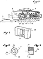
- Figure 4 is a perspective view of the rocker.
- Figure 5 is a front view of the bias ring.
- FIG. 6 is a side view of the ring of FIG. 5.
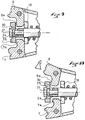
- Figures 7 to 11 are partial sectional views of the retaining element at the connection between the wings and the tie rod, and illustrate the operation of this connection.
- Figure 12 shows schematically in front view the connection between the ring and the operating lever.
- FIG. 13 represents in side view the construction of FIG. 12.
- FIG. 14 shows a top view of a set of two retaining elements according to the embodiment of FIG. 1.
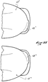
- FIG. 15 represents in top view the front of two shoes of a pair particularly adapted to the set of retaining elements of FIG. 14.
- Figure 16 illustrates an alternative embodiment of the front of the shoes.
- Figure 17 shows another embodiment of the shoes.
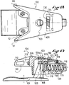
- Figure 18 shows a top view of a retaining element in another embodiment of the invention.
- Figure 19 shows in side view and in section the element of the previous figure.
- FIG. 20 is a sectional and top view of the element in FIG. 18.
- Figure 21 is a top view in partial section at a level higher than that of Figure 20
- Figure 22 shows a front view of the operating button.
- Figure 23 shows the button in side view.
- FIGS 24 and 25 illustrate the two modes of operation of the retainer.
- Figure 26 shows in top view and in section a retaining element according to another embodiment of the invention.
- Fig 27 is a side view in partial section of the element of Figure 26.
- Figure 28 shows the control switch, seen from the front, in the middle position.
- Figure 29 shows the switch in one of its polarization positions.
- Figures 1 to 3 show by way of illustration of the invention a retaining element 1 of a set of elements comprising two elements.
- the two elements of the set are constructed identically.
- the element 1 shown in Figures 1 to 3 comprises a base 2 surmounted by a hollow body 3 having a side wall and an upper cover.
- the base 2 extends rearward to form a support plate 5 intended to receive the shoe sole.
- the retaining element also has a jaw formed by two wings 7 and 8 for retaining the boot.
- the wings are independent, respectively articulated around vertical axes 9 and 10.
- the wings extend respectively inwards, beyond the axes 9 and 10 by returns 7a and 8a .
- the wings include a sole clamp which ensures the vertical retention of the shoe, in addition to the lateral retention.
- the jaw could have another nature, in particular being in one piece, connected integrally to a body mounted to pivot around a central pivot. Many known constructions are possible.
- the jaw At rest, the jaw has a position substantially aligned with the longitudinal axis defined by the ski. In the illustrated case, at rest, the wings 7 and 8 are closed towards the median longitudinal axis which is shown diagrammatically by its trace 11 in FIG. 2.
- the body 3 of the retaining element houses a spring 12, to which are transmitted the stresses which the shoe exerts on the wings of the jaw, and which, in return, exerts on the wings an elastic restoring force in the direction of their respective rest position.
- the spring is connected to the jaw by a movement transmission link.
- connection between the spring and the wings of the jaw comprises a longitudinal rod 13 which is cylindrical.
- the tie rod is engaged in the turns of the spring. It has at its front end a stop washer 14 against which the front end of the spring bears.
- the washer is connected to the end of the spring by a screw 15 which makes it possible to adjust the initial compression of the spring.
- the screw 15 is accessible from the front of the retaining element through an opening in the cover.
- the spring bears against a support wall 18 which is integral with the body or its base.
- the support wall 18 also serves as a stop for the returns 7a and 8a of the wings, for rotation of the wings inwards. This position in abutment against the support wall defines the rest position of each of the wings.
- the tie rod crosses the wall 18 and opens rearward between the two wings. At this level, it has a part 20 of smaller diameter, with a head 21. At the birth of this part of smaller diameter, the tie rod has a shoulder 22. On the part of smaller diameter are mounted a ring 24, on the side of the shoulder 22, and a floating rocker 25 on the side of the head 21.
- the floating rocker is wider than the head 21, and its dimensions are such that it gives the returns 7a and 8a of the wings a surface d 'support by which the returns of the wings can urge the tie back and forth against the return force of the spring.
- the part 20 of smaller diameter is an independent element which is assembled for example by screwing or any other means suitable for the rest of the tie rod.
- the rocker 25 is held on the part 20 of the tie rod, pressing between its head 21 and the returns 7a and 8a of the wings.
- the head 21 of the tie has a square section, and the tie has laterally two beads which give good support for the rocker, in particular during the oscillating movements which will be described later.
- the rocker 25 bears against the ring 24.
- the ring 24 is pivotally mounted around the part 20 of the tie rod. Towards the front, the ring bears against the shoulder 22.
- the ring has an outside diameter equal to that of the front part of the tie rod, but this is not essential.
- the ring has a length greater than the travel of the tie between the rest position and the release of the shoe.
- the assembly of the rocker and of the ring is provided so that, at least at rest, the ring can pivot freely around the part 20. That is to say that the rocker and the ring are mounted on the tie rod, between the head and the shoulder 22 with a slight play in a longitudinal direction.
- the rocker 25 is floating, that is to say it can oscillate in a horizontal plane, depending on the position and the displacement of its various supports.
- the rocker has a large central opening 27 of rectangular shape.
- the width of this opening is greater than the diameter of the part 20 of the tie rod, and, preferably, this part 20 has a flange 28 with a rounded edge, the outside diameter of which is substantially equal to the width of the opening. 27.
- This flange serves to support the oscillation of the rocker, which will be described in more detail later.
- the width of the opening 27 is however less than the diameter of the ring 24.
- the opening 27 has a height which is slightly greater than the outside diameter of the ring 25.
- the rocker 25 is provided so that the part 20 is halfway up. Any suitable means is suitable.
- the ring 25 has on the side of the rocker a flat support surface, which is vertical, except on a quarter of a circle where the support surface is recessed.
- the flat and vertical zone is marked at 29 in the figures, and the recessed zone at 30. In the position of the ring shown in FIGS. 1 and 2, this zone 30 is aligned with the median longitudinal plane, downwards , under part 20 of the tie. It could as well be above part 20. This position will be qualified in the following as middle position
- Figures 7 and 8 show the connection between the wings and the tie in the middle position of the ring.
- the wings are at rest, in the closed position.
- one of the wings, the wing 7 in this case, has opened.
- the return 7a of the wing has caused the rocker 25.
- the rocker 25 is held on one side by the head 20 of the tie rod, and on the other side, by reaction, it bears against the ring 24 on the side and on the other side of the median longitudinal axis.
- the rocker moves with the tie rod staying perpendicular to the tie rod.
- FIG. 9 represents the construction after a rotation of the ring 24 over a quarter of a turn. This rotation brought the recessed area 30 of the rocker towards the return 8a of the wing 8.
- wing 8 has opened. In its rotational movement, the wing has driven the rocker 25.
- the rocker rests on the head of the tie rod, and, by reaction on the ring 24 in the zone diametrically opposite to the zone 30.
- the rocker behaves with the same way as what was described previously.
- FIG. 11 illustrates the rotation of the other wing, that is to say the wing 7.
- the rocker drives the head 21 of the tie rod, but this time, the rocker rests by reaction not more against the ring 24, but against the return 8a of the other wing. Indeed, the rocker cannot find a support against the ring 24, because of the recessed area 30.
- the wing 8 is retained by the support wall 18.
- the rocker 25 no longer directly transmits its movement to the tie rod, it functions as a lever, which pivots on its support on the return 8a. Given the difference in the lever arm, the restoring force that opposes the opening of the wing is multiplied. The opening of the wing 7 is facilitated in this position of the ring 24.
- the zone 30 is sufficiently set back so that the wing 7 releases the shoe before the rocker 25 reaches the bottom of the zone 30. In this way, the rocker 30 remains in abutment against the return of the wing 8 , and the multiplier effect is maintained.
- the opening 27 of the rocker 30 is provided in height so as not to hinder the oscillation of the rocker, that is to say that it is greater than the outside diameter of the ring.
- the ring 24 can also be pivoted in the other direction, to obtain the same multiplying effect with the opening of the other wing.
- the retainer further includes means for manually determining the position of the ring.
- the ring 24 has on the half of its periphery a grooved area 34.
- the grooves are oriented parallel to the longitudinal direction of movement of the tie rod.
- this zone is opposite the zone 30 of the ring, and, in the middle position of the ring, this zone is located on the top of the ring.
- a rack 35 is provided to mesh with the grooves of the ring 24.
- the rack 35 is guided in a transverse translational movement in a groove carried by the support wall 18.
- Naturally any other suitable guide means is suitable.
- the rack carries in its upper part a vertical rod 36.
- the rod 36 is engaged in the teeth of a lever 37 in the form of a fork.
- the lever is pivotally mounted about a vertical axis 38 which passes through the cover 3 of the retaining element.
- the vertical axis 38 is embedded in an operating lever 40 designed to be actuated simply by hand or with the ski pole.
- the lever may have any suitable means, for example small bowls 39 provided for receiving the tip of the ski pole.
- the assembly is designed so that a determined angle rotation of the control lever 40 causes the ring 24 to rotate a quarter turn on one side or the other from its median position.
- the lever 40 is visible in Figure 1 above the cover. It is shown in its middle position which corresponds to the middle position of the ring 24.
- 40a and 40b have identified the two directions in which the operating lever must be oriented in order to bring the ring 24 into one either of the so-called polarization positions of the retaining element which produce a release threshold for the asymmetrical shoe, lower on one side than on the other.
- the ring 24 is mounted on the part 20 of the tie rod with a slight play, so that its rotation can be controlled without significant effort when the element is in the rest position.
- the ring 24 is actually biased against the shoulder of the tie rod only when a retaining wing of the shoe is biased.
- the tie moves in a longitudinal direction.
- the rack does not accompany this movement, but its teeth slide along the grooves of the ring 24.
- the length of the ring has been provided for greater than the maximum travel of longitudinal displacement of the tie rod.
- Figure 14 shows a set of two retaining elements 1 'and 1' 'which are identical to the element 1 described above. These elements are shown in their position ready for footing, that is to say that the element ready to footwear by the right shoe is to the right of the other element, and the element intended to be shod by the left shoe. is to the left of the other element in the set.
- Each element has an operating lever 40 'and 40' 'identical to lever 40.
- the two operating levers have been oriented in opposite and symmetrical directions, to polarize the retaining elements of symmetrically, so that for each foot of the skier, the boot is released more easily for release of the boot towards the outside of the element, corresponding to a rotation of the foot towards the inside.
- the maneuvering levers are oriented according to the appropriate polarization, and they are brought back to the middle position at the end of each use. For example, for each use, the skier presents his skis on the snow next to each other ready to be put on, and directs the levers appropriately according to the relative position of the skis.
- the skier leaves the operating levers in their position.
- the respective orientation of the levers is suitable or not. If it is suitable, it does not modify the setting of the operating levers, in fact, the retaining elements are correctly polarized. If the levers are not in the correct position, rather than inverting the relative position of the skis, the skier simply reverses the orientation of the levers. In doing so, it brings back each of the elements of retained in a correct position. This maneuver is carried out in a simple manner, and does not require any manipulation of the skis.
- levers can also be placed in the middle position, in which case the skis can be reversed without problem.
- the shoes may have a visual cue which acts as a key.
- the two shoes 43 'and 43' ' have at the front a graphic representing two symmetrical arrows 44', 44 '', indicating the direction in which the operating levers must be pivoted.
- Figure 16 shows the front of two shoes 45 'and 45' 'which respectively carry graphics 46', 46 '' suggestively indicating the correct orientation of the levers. The graphics indeed encourage to orient the levers parallel to the lines.
- the shoes can also be equipped with a mechanical type polarizing device.
- Figure 17 shows the front of shoes 47 'and 47' 'with a part 48', 48 '' projecting from the front, above the standard area.
- These projections are located at the height of the operating levers, when the shoe is engaged in the retaining element. They have the function of preventing the engagement of the shoe in the retaining elements if their respective lever is not in the suitable position, or the middle position.
- Figure 18 relates to another embodiment of the invention.
- the illustrated retaining element is largely known from the patent application published under the number FR 2 517 214.
- This element 100 comprises a base 101 intended to be secured to the ski by any suitable means, for example screws.
- the base carries a pivot 102 surmounted by a screw 103.
- the body 106 of the fixing element is somehow suspended from the head of the screw, and by more or less screwing the screw into the pivot , it is possible to adjust the height of the body in relation to the ski.
- the base and the screw form on the rear two support lines against Iesterrorism the body 106 of the retaining element is supported.
- the support lines converge towards the head of the screw, and the body is supported on the pivot by three zones or points, two marked 104a and 105a located in the lower part of the pivot, and the head 103a of the screw 103.
- the base On its front face, the base has a transverse face 108 against which the return spring 115 of the retaining element exerts its action.
- the body Towards the rear, the body has a shoe retaining jaw.
- the jaw comprises two wings 110 and 111 which form with the body an assembly monobloc, or quasi-monobloc if one takes into account the means allowing to adjust the angular opening of the wings. These means are known and are not referenced in the figures.
- the wings 110 and 111 provide lateral retention of the shoe. Given their position, the wings 110 and 111 retain the shoe by what is called a grip on the upper.
- the standardized toe of the shoe has in fact in a known manner a lower part of the sole, surmounted by an upper part which forms the base of the upper. It is on this part that the wings 110 and 111 exert their action. Of course, this is not limiting, and the other grip of the toe, called grip on the sole is also possible.
- the vertical retention is provided by the lower part of the wings which provides a bearing face for the upper part of the sole. This is also not limiting.
- the jaw also includes a central support point against which bears the most advanced part of the upper of the shoe.
- the binding element has an elastic return mechanism of the body in position aligned with the vertical and longitudinal median plane defined by the longitudinal direction of the ski.
- This mechanism comprises in a known manner a spring 115 housed in a longitudinal recess of the body which is closed by a threaded plug 116.
- One end of the spring bears on this plug whose screwing makes it possible to adjust the hardness of the retaining element, it that is to say the initial compression of the spring 115.
- the piston has on its bearing face two lateral chamfers 118a and 118b, which are slightly inclined.
- the bearing face of the piston thus has a central face 118c of triangular shape, seen from the front, and two lateral chamfers 118a and 118b.
- the spring 115 maintains the body in a stable position aligned with the median plane.
- the jaw and the body tend to pivot around one or the other of the support lines of the pivot 102, against the restoring force developed by the spring.
- the rotation of the jaw is sufficient to allow the release of the shoe.
- the stress threshold beyond which the shoe is released is commonly called the trigger threshold. This threshold depends directly on the nature of the spring and its initial compression. With the elements which have been described so far, the triggering threshold is substantially the same for the two directions of pivoting of the body, on one side or the other of the median plane.
- the retaining element has an adjustment mechanism acting on the trigger threshold of the jaw according to whether it moves to one side or the other from its aligned position.
- these means comprise a flat flap 119 which is interposed between the piston 118 and the face 108 of the pivot 104 support.
- the piston 118 bears on the face 108 of the pivot 104 by l through flap 119.
- the flap 119 has laterally two beads 120 and 121 whose spacing is substantially equal to the width of the face 108, so that in the aligned position, the flap is freely fitted on the face 108 and pressed against this face.
- the flap in its upper part, has a return 122 which maintains the flap vertically by pressing against the piston 118.
- the bearing surface of the flap 119 on the pivot 104 is wider than the bearing surface of the piston 118 on the flap 119.
- Means make it possible to control the movement of the flap, by associating it either with the pivot, or else with the body of the retaining element.
- the flap has in its upper part a tab 125 projecting, aligned with the median plane.
- a movable latch 126, 127 mounted on a transverse joint 128 carried by the body.
- Each latch is movable between a low position where it blocks the relative movement of the cleat on the side where the latch is located, and a high position where it allows the relative movement of the cleat.
- An elastic element for example a pin spring 129 recalls each movable latch in the high position.
- An operating button 130 is located above the body in the vicinity of the movable end of the latches.
- the button has an upper part accessible from above the cover of the body, it crosses the cover, and has below a ramp 131 for controlling the position of the latches.
- the button 130 is movable along a transverse direction. For example, it is guided through a transverse opening in the wall of the body.
- the ramp 131 has three parts, a horizontal central part 131a, and, on each side of this central part, an inclined part 131b and 131c respectively.
- the button has three main positions, a central position substantially aligned with the longitudinal central axis. In this position, the horizontal part 131a immobilizes the two latches in the low position.
- the flap 119 is slaved to the movement of the body.
- Figure 24 illustrates this mode of operation.
- the release of the boot is obtained after a determined angle rotation of the body, for a triggering threshold defined by the compression of the spring 115.
- the compression of the body is relatively strong. This compression depends on the bearing faces 102 of the pivot and on the facing surface of the flap 119.
- the button can be moved laterally on either side of this middle position. In each of the lateral positions of the button, one of the latches is released, and rises under the action of the spring 129.
- the release of the boot is achieved for less compression of the spring.
- the trigger threshold has been lowered.
- the button 130 polarizes the retaining element by modifying its triggering threshold for one of its directions of pivoting.
- the two inclined parts 131b and 131c of the ramp serve to lower one or the other of the latches when the button is brought back from a lateral position of polarization to the middle position.
- the retaining element is intended to form an assembly with another identical retaining element.
- the operating buttons must be adjusted either in the middle position, or in symmetrical positions corresponding to a lower trigger threshold for a release of the shoe corresponding to a twist of the leg in the direction in which the foot is driven towards the interior.
- the button 130 can have any suitable means, for example a small bowl 135 provided for receiving the tip of the stick.
- the shoes used with the retaining elements may have a coding mark which encourages them to adjust each of the buttons in the appropriate position.
- FIG. 26 represents a retaining element 141 which is of the same type as that of FIG. 1, with in particular the spring 12, the tie rod 13, the wall 18, the rocker 25 and the ring 24.
- the difference is that the rotation of the ring 24 is controlled electrically, not mechanically.
- the ring 24 is here driven in rotation by an electric motor 142 which drives a toothed wheel 143 whose teeth are engaged on the grooves of the ring.
- the motor is fixed for example to the wall 18. It is of any suitable type, and for example, it is provided for example to make rotations with a pitch corresponding to a quarter turn of the wheel toothed.
- the rotation of the motor is controlled by a switch, the movable part of which has three stable positions, and is at least partially accessible from the outside, for example above the cover of the retaining element.
- a switch is represented in FIG. 27 under the reference 145.
- This switch has a body 146 which is fixed to the cover of the retaining element, and a movable part 147 which is oriented in a transverse direction, and articulated around a longitudinal axis. Above the cover, the mobile part has two open "V" shaped faces.
- Figure 28 shows the movable part in its middle position, which corresponds to the middle position of the ring.
- Figure 29 shows the movable part in one of its stable lateral positions. This position is for example imposed by pressing on one of the faces of the movable part, by means of the stick.
- the switch controls the rotation of the motor 142 in order to rotate the ring 24 towards the polarization position which is assigned to it.
- the position of the movable part of the switch is also indicative of the polarization of the retaining element. In other words, depending on the face of the switch which is pressed towards the cover, it is possible to see whether the retaining element is polarized as a right element or as a left element.
- the switch 145 and the motor are coupled by electrical means, in particular a battery and connectors. These means are of a known type and will not be described in detail.
- the present description is not limited to the various embodiments and variants which have been described, and numerous variants are possible.
- the invention can be adapted to other known constructions of retaining element than those which have been described.
- the operating buttons could be placed in front of the retaining element, on the side, or in any other appropriate zone.
Landscapes
- Footwear And Its Accessory, Manufacturing Method And Apparatuses (AREA)
- Braking Arrangements (AREA)
- Sheet Holders (AREA)
Applications Claiming Priority (2)
| Application Number | Priority Date | Filing Date | Title |
|---|---|---|---|
| FR9414072A FR2727029B1 (fr) | 1994-11-21 | 1994-11-21 | Ensemble d'elements de retenue de chaussures sur des planches de glisse |
| FR9414072 | 1994-11-21 |
Publications (2)
| Publication Number | Publication Date |
|---|---|
| EP0712647A1 true EP0712647A1 (de) | 1996-05-22 |
| EP0712647B1 EP0712647B1 (de) | 1998-03-04 |
Family
ID=9469101
Family Applications (1)
| Application Number | Title | Priority Date | Filing Date |
|---|---|---|---|
| EP95115918A Expired - Lifetime EP0712647B1 (de) | 1994-11-21 | 1995-10-10 | Haltevorrichtung für Skischuhe auf Gleitbrettern |
Country Status (6)
| Country | Link |
|---|---|
| US (1) | US5785343A (de) |
| EP (1) | EP0712647B1 (de) |
| JP (1) | JPH08215372A (de) |
| AT (1) | ATE163558T1 (de) |
| DE (1) | DE69501706T2 (de) |
| FR (1) | FR2727029B1 (de) |
Cited By (2)
| Publication number | Priority date | Publication date | Assignee | Title |
|---|---|---|---|---|
| EP0807453A1 (de) * | 1996-05-15 | 1997-11-19 | Salomon S.A. | Vorderbackensystem für Schuhe auf Skis |
| EP0807454A1 (de) * | 1996-05-15 | 1997-11-19 | Salomon S.A. | Vorderbackensystem für Schuhe auf Skis |
Families Citing this family (6)
| Publication number | Priority date | Publication date | Assignee | Title |
|---|---|---|---|---|
| FR2770787B1 (fr) * | 1997-11-07 | 2000-01-14 | Rossignol Sa | Perfectionnement pour dispositif de retenue d'une chaussure sur un ski |
| DE60102505T2 (de) * | 2000-04-14 | 2005-03-03 | Look Fixations S.A. | Schuh zum gemeinsamen Gebrauch mit einem Sportgerät, mit Identifizierungsmittel für linken/rechten Schuh |
| FR2808453B1 (fr) * | 2000-05-04 | 2002-08-02 | Salomon Sa | Element de retenue de l'avant d'une chaussure sur un ski |
| FR2808454B1 (fr) * | 2000-05-04 | 2002-08-02 | Salomon Sa | Element de retenue de l'avant d'une chaussure sur un ski |
| EP1190744A3 (de) * | 2000-09-23 | 2003-04-16 | INGENIEURBÜRO FLUGWESEN & BIOMECHANIK IFB AG | Sicherheitsskibindung mit differenzierter Auslösung |
| FR2819422B1 (fr) * | 2001-01-12 | 2003-04-25 | Salomon Sa | Element de retenue avant d'une chaussure de ski alpin |
Citations (11)
| Publication number | Priority date | Publication date | Assignee | Title |
|---|---|---|---|---|
| FR1503849A (fr) | 1966-10-14 | 1967-12-01 | Salomon & Fils F | Dispositif de déclenchement dissymétrique pour fixations de skis |
| FR1503847A (fr) | 1966-10-14 | 1967-12-01 | Salomon & Fils F | Perfectionnement aux fixations de ski à verrouillage par bille |
| FR1503848A (fr) | 1965-12-02 | 1967-12-01 | Salomon & Fils F | Fixation à déclenchement dissymétrique pour skis |
| DE1807074A1 (de) | 1968-11-05 | 1970-05-27 | Augustin Dr Ing Dietmar | Asymmetrische Schisicherheitsbindungen (Vorderbacken) gegen Drehstuerze |
| DE1963149A1 (de) * | 1969-12-17 | 1971-06-24 | Ludwig Berchtold | Sicherheitsvorderbacken fuer Skibindungen |
| AT313761B (de) * | 1970-12-24 | 1974-03-11 | Smolka & Co Wiener Metall | Federverrastung für Skibindungen |
| DE2454577A1 (de) * | 1974-11-18 | 1976-05-20 | Ver Baubeschlag Gretsch Co | Sicherheitsskibindung |
| DE2802251A1 (de) * | 1978-01-19 | 1979-07-26 | Ver Baubeschlag Gretsch Co | Sicherheitsskibindung mit einem seitlich ausschwenkbaren sohlenhalter |
| FR2517214A1 (fr) | 1981-12-02 | 1983-06-03 | Salomon & Fils F | Fixation de securite destinee a etre montee sur un ski pour maintenir une chaussure de ski sur ce dernier |
| EP0302309A2 (de) * | 1987-08-03 | 1989-02-08 | Marker Deutschland GmbH | Vorderbacken für Sicherheits-Skibindungen |
| DE4305327C1 (de) * | 1993-02-20 | 1994-03-03 | Peter Wirnsberger | Skibindung |
Family Cites Families (6)
| Publication number | Priority date | Publication date | Assignee | Title |
|---|---|---|---|---|
| US3228708A (en) * | 1960-04-20 | 1966-01-11 | Miller Earl Andrew | Clamping jaws for ski bindings |
| US3666280A (en) * | 1967-12-14 | 1972-05-30 | Smolka & Co Wiener Metall | Ski binding |
| JPS6037744B2 (ja) * | 1980-06-19 | 1985-08-28 | 安 堀内 | スキ−締具 |
| JPH0722082Y2 (ja) * | 1990-09-07 | 1995-05-24 | ダイワ精工株式会社 | スキー靴 |
| FR2722372B1 (fr) * | 1994-07-13 | 1996-10-04 | Salomon Sa Societe Anonyme | Chaussure de sport, notamment chaussure de ski alpine |
| FR2722373B1 (fr) * | 1994-07-13 | 1996-10-04 | Salomon Sa Societe Anonyme | Ensemble d'une chaussure et d'un element de retenue, notamment pour la pratique du ski |
-
1994
- 1994-11-21 FR FR9414072A patent/FR2727029B1/fr not_active Expired - Fee Related
-
1995
- 1995-10-10 DE DE69501706T patent/DE69501706T2/de not_active Expired - Fee Related
- 1995-10-10 EP EP95115918A patent/EP0712647B1/de not_active Expired - Lifetime
- 1995-10-10 AT AT95115918T patent/ATE163558T1/de not_active IP Right Cessation
- 1995-11-17 US US08/559,140 patent/US5785343A/en not_active Expired - Fee Related
- 1995-11-21 JP JP7302349A patent/JPH08215372A/ja not_active Withdrawn
Patent Citations (11)
| Publication number | Priority date | Publication date | Assignee | Title |
|---|---|---|---|---|
| FR1503848A (fr) | 1965-12-02 | 1967-12-01 | Salomon & Fils F | Fixation à déclenchement dissymétrique pour skis |
| FR1503849A (fr) | 1966-10-14 | 1967-12-01 | Salomon & Fils F | Dispositif de déclenchement dissymétrique pour fixations de skis |
| FR1503847A (fr) | 1966-10-14 | 1967-12-01 | Salomon & Fils F | Perfectionnement aux fixations de ski à verrouillage par bille |
| DE1807074A1 (de) | 1968-11-05 | 1970-05-27 | Augustin Dr Ing Dietmar | Asymmetrische Schisicherheitsbindungen (Vorderbacken) gegen Drehstuerze |
| DE1963149A1 (de) * | 1969-12-17 | 1971-06-24 | Ludwig Berchtold | Sicherheitsvorderbacken fuer Skibindungen |
| AT313761B (de) * | 1970-12-24 | 1974-03-11 | Smolka & Co Wiener Metall | Federverrastung für Skibindungen |
| DE2454577A1 (de) * | 1974-11-18 | 1976-05-20 | Ver Baubeschlag Gretsch Co | Sicherheitsskibindung |
| DE2802251A1 (de) * | 1978-01-19 | 1979-07-26 | Ver Baubeschlag Gretsch Co | Sicherheitsskibindung mit einem seitlich ausschwenkbaren sohlenhalter |
| FR2517214A1 (fr) | 1981-12-02 | 1983-06-03 | Salomon & Fils F | Fixation de securite destinee a etre montee sur un ski pour maintenir une chaussure de ski sur ce dernier |
| EP0302309A2 (de) * | 1987-08-03 | 1989-02-08 | Marker Deutschland GmbH | Vorderbacken für Sicherheits-Skibindungen |
| DE4305327C1 (de) * | 1993-02-20 | 1994-03-03 | Peter Wirnsberger | Skibindung |
Cited By (2)
| Publication number | Priority date | Publication date | Assignee | Title |
|---|---|---|---|---|
| EP0807453A1 (de) * | 1996-05-15 | 1997-11-19 | Salomon S.A. | Vorderbackensystem für Schuhe auf Skis |
| EP0807454A1 (de) * | 1996-05-15 | 1997-11-19 | Salomon S.A. | Vorderbackensystem für Schuhe auf Skis |
Also Published As
| Publication number | Publication date |
|---|---|
| EP0712647B1 (de) | 1998-03-04 |
| JPH08215372A (ja) | 1996-08-27 |
| ATE163558T1 (de) | 1998-03-15 |
| FR2727029A1 (fr) | 1996-05-24 |
| FR2727029B1 (fr) | 1997-01-24 |
| US5785343A (en) | 1998-07-28 |
| DE69501706D1 (de) | 1998-04-09 |
| DE69501706T2 (de) | 1998-07-16 |
Similar Documents
| Publication | Publication Date | Title |
|---|---|---|
| EP0088673B1 (de) | Vorrichtung für Langlaufski | |
| CH690819A5 (fr) | Fixation pour snowboard. | |
| CA2146194A1 (fr) | Dispositif de fixation d'une chaussure a un organe de glisse | |
| FR2678490A1 (fr) | Chaussure de ski avec dispositif de blocage de tige. | |
| FR2583272A1 (fr) | Chaussure de ski alpin | |
| EP0620711B1 (de) | Langlaufschischuh und kombination von schi, bindung und schuh | |
| EP0521282A1 (de) | Skischuh mit Schwenksperre für den Schaft | |
| EP0546260A2 (de) | Vorrichtung zur Längenverstellung einer alpinen Bindung | |
| FR2547508A1 (fr) | Fixation de securite pour ski | |
| EP0712647B1 (de) | Haltevorrichtung für Skischuhe auf Gleitbrettern | |
| EP0692286B1 (de) | Kombination von Skischuh und Bindung | |
| WO1996036407A1 (fr) | Dispositif de retenue d'une chaussure sur une planche de glisse | |
| EP0193686B1 (de) | Rückhaltevorrichtung für einen Schuh auf einem Ski | |
| EP0917834A1 (de) | Langlauf-schischuh | |
| EP0105011A1 (de) | Skischuh mit eingebauter Multirichtstrahlbindung | |
| EP0712648B1 (de) | Bindungssystem für Schuhe auf Gleitbrettern | |
| EP0739646B1 (de) | Bindungssystem für Schuhe auf Skiern | |
| EP0332546B1 (de) | Bindung eines Schuhs auf einen Langlaufski | |
| EP0785003B1 (de) | Bindungssystem für Schuhe auf Skis | |
| EP0820331B1 (de) | Bindungssystem für schuhe auf skis | |
| FR2738156A1 (fr) | Dispositif de fixation et de deverrouillage automatique | |
| EP0766930B1 (de) | Durch ein Gleitschuhpaar gebildete Einheit, insbesondere Schischuhe, und ein Befestigungselementepaar zum Befestigen dieses Schuhe | |
| FR2754726A1 (fr) | Dispositif de liaison entre une chaussure et un article de sport | |
| FR2582531A3 (fr) | Fixation de ski | |
| EP4555889A1 (de) | Verriegelungsvorrichtung für einen sportschuh |
Legal Events
| Date | Code | Title | Description |
|---|---|---|---|
| PUAI | Public reference made under article 153(3) epc to a published international application that has entered the european phase |
Free format text: ORIGINAL CODE: 0009012 |
|
| AK | Designated contracting states |
Kind code of ref document: A1 Designated state(s): AT CH DE IT LI |
|
| 17P | Request for examination filed |
Effective date: 19960619 |
|
| GRAG | Despatch of communication of intention to grant |
Free format text: ORIGINAL CODE: EPIDOS AGRA |
|
| GRAG | Despatch of communication of intention to grant |
Free format text: ORIGINAL CODE: EPIDOS AGRA |
|
| GRAH | Despatch of communication of intention to grant a patent |
Free format text: ORIGINAL CODE: EPIDOS IGRA |
|
| 17Q | First examination report despatched |
Effective date: 19970818 |
|
| GRAH | Despatch of communication of intention to grant a patent |
Free format text: ORIGINAL CODE: EPIDOS IGRA |
|
| GRAA | (expected) grant |
Free format text: ORIGINAL CODE: 0009210 |
|
| AK | Designated contracting states |
Kind code of ref document: B1 Designated state(s): AT CH DE IT LI |
|
| PG25 | Lapsed in a contracting state [announced via postgrant information from national office to epo] |
Ref country code: IT Free format text: LAPSE BECAUSE OF FAILURE TO SUBMIT A TRANSLATION OF THE DESCRIPTION OR TO PAY THE FEE WITHIN THE PRESCRIBED TIME-LIMIT;WARNING: LAPSES OF ITALIAN PATENTS WITH EFFECTIVE DATE BEFORE 2007 MAY HAVE OCCURRED AT ANY TIME BEFORE 2007. THE CORRECT EFFECTIVE DATE MAY BE DIFFERENT FROM THE ONE RECORDED. Effective date: 19980304 |
|
| REF | Corresponds to: |
Ref document number: 163558 Country of ref document: AT Date of ref document: 19980315 Kind code of ref document: T |
|
| REG | Reference to a national code |
Ref country code: CH Ref legal event code: EP |
|
| REG | Reference to a national code |
Ref country code: CH Ref legal event code: NV Representative=s name: CABINET ROLAND NITHARDT CONSEILS EN PROPRIETE INDU |
|
| REF | Corresponds to: |
Ref document number: 69501706 Country of ref document: DE Date of ref document: 19980409 |
|
| PLBE | No opposition filed within time limit |
Free format text: ORIGINAL CODE: 0009261 |
|
| STAA | Information on the status of an ep patent application or granted ep patent |
Free format text: STATUS: NO OPPOSITION FILED WITHIN TIME LIMIT |
|
| 26N | No opposition filed | ||
| PG25 | Lapsed in a contracting state [announced via postgrant information from national office to epo] |
Ref country code: LI Free format text: LAPSE BECAUSE OF NON-PAYMENT OF DUE FEES Effective date: 19991031 Ref country code: CH Free format text: LAPSE BECAUSE OF NON-PAYMENT OF DUE FEES Effective date: 19991031 |
|
| REG | Reference to a national code |
Ref country code: CH Ref legal event code: PL |
|
| PGFP | Annual fee paid to national office [announced via postgrant information from national office to epo] |
Ref country code: AT Payment date: 20031013 Year of fee payment: 9 |
|
| PGFP | Annual fee paid to national office [announced via postgrant information from national office to epo] |
Ref country code: DE Payment date: 20031023 Year of fee payment: 9 |
|
| PG25 | Lapsed in a contracting state [announced via postgrant information from national office to epo] |
Ref country code: AT Free format text: LAPSE BECAUSE OF NON-PAYMENT OF DUE FEES Effective date: 20041010 |
|
| PG25 | Lapsed in a contracting state [announced via postgrant information from national office to epo] |
Ref country code: DE Free format text: LAPSE BECAUSE OF NON-PAYMENT OF DUE FEES Effective date: 20050503 |