EP4555889A1 - Verriegelungsvorrichtung für einen sportschuh - Google Patents
Verriegelungsvorrichtung für einen sportschuh Download PDFInfo
- Publication number
- EP4555889A1 EP4555889A1 EP23425062.9A EP23425062A EP4555889A1 EP 4555889 A1 EP4555889 A1 EP 4555889A1 EP 23425062 A EP23425062 A EP 23425062A EP 4555889 A1 EP4555889 A1 EP 4555889A1
- Authority
- EP
- European Patent Office
- Prior art keywords
- locking
- blade
- axis
- locking element
- rotation
- Prior art date
- Legal status (The legal status is an assumption and is not a legal conclusion. Google has not performed a legal analysis and makes no representation as to the accuracy of the status listed.)
- Pending
Links
Images


Classifications
-
- A—HUMAN NECESSITIES
- A43—FOOTWEAR
- A43B—CHARACTERISTIC FEATURES OF FOOTWEAR; PARTS OF FOOTWEAR
- A43B5/00—Footwear for sporting purposes
- A43B5/04—Ski or like boots
- A43B5/0427—Ski or like boots characterised by type or construction details
- A43B5/0452—Adjustment of the forward inclination of the boot leg
- A43B5/0454—Adjustment of the forward inclination of the boot leg including flex control; Dampening means
- A43B5/0456—Adjustment of the forward inclination of the boot leg including flex control; Dampening means with the actuator being disposed at the rear side of the boot
Definitions
- the invention relates to a locking device for locking a rotational joint between a shell bottom and a collar of a sports shoe.
- the invention also relates to a sports shoe, in particular a ski boot, comprising such a locking device.
- For skiing we know sports boots comprising a lower shell and a cuff that rotates around the lower shell.
- the lower shell envelops the foot below the ankle while the cuff envelops the lower leg above the ankle.
- the articulation between the lower shell and the cuff allows easy insertion of the foot into the boot, as well as natural walking since the ankle joint is not blocked.
- the articulation between the lower shell and the cuff must be blocked in order to effectively control the skis.
- locking devices also known as "ski-walk”
- These devices include a lever that can be operated by hand and allows the boot to be chosen between two configurations.
- the first configuration called “ski”
- the second configuration called “walk”
- walks releases the joint between the cuff and the bottom of the shell.
- ski boots are particularly harsh: they are exposed to very low temperatures and very high humidity. In addition, they are likely to receive numerous impacts, particularly in the event of a fall by the user. Under these conditions, the locking devices integrated into these boots become damaged too quickly. Once damaged, a locking device can become even more difficult to operate and/or may no longer correctly lock the cuff in relation to the bottom of the shell in ski configuration, or may even be completely unusable.
- the aim of the invention is to provide a locking device which overcomes the above drawbacks and improves the locking devices known from the prior art.
- the invention aims to provide locking devices which are simple to manufacture, reliable, robust, easy to handle, and which make it possible to effectively block the collar relative to the bottom of the shell when they are in the ski configuration.
- the locking device may further comprise a return means, in particular a torsion spring, the return means comprising a first end and a second end opposite the first end, the first end being in contact with the lever, the second end being in contact with the first bearing surface of the rocker, the return means being configured so as to be energized transiently when the lever is moved between its locking position and its unlocking position.
- a return means in particular a torsion spring, the return means comprising a first end and a second end opposite the first end, the first end being in contact with the lever, the second end being in contact with the first bearing surface of the rocker, the return means being configured so as to be energized transiently when the lever is moved between its locking position and its unlocking position.
- the locking element may comprise a recess, and the second bearing surface of the rocker may be in contact with an edge of said recess.
- the lever can be movable in rotation about a second axis of rotation between its locking position and its unlocking position, the second axis of rotation being parallel to the first axis of rotation.
- the blade can be mounted to rotate about a third axis of rotation, the blade being intended to pivot about the third axis of rotation when the locking element is in the unlocked position and the collar pivots relative to the bottom of the hull, the third axis of rotation being parallel to the first axis of rotation.
- the locking device may comprise a housing intended to be fixed to the collar or to the bottom of the shell, the housing comprising a guide means for guiding the locking element in translation between its locking position and its unlocking position.
- the housing may further comprise at least one guide intended to guide the blade in translation relative to the housing when the collar pivots relative to the bottom of the hull.
- the locking device may further comprise a first shaft extending along said first axis of rotation, the housing comprising two opposite lateral flanks supporting said first shaft.
- the lever may comprise a second shaft, the lever being intended to pivot around the second shaft between its locking position and its unlocking position, the two lateral flanks also supporting said second shaft.
- the locking element can be movable in translation parallel to a fourth axis between its locking position and its unlocking position, and the blade can move in a plane substantially perpendicular to the fourth axis when the collar pivots relative to the bottom of the hull.
- the locking member may include a first guide surface and the blade may include a second guide surface, the first guide surface cooperating with the second guide surface to guide movement of the blade relative to the locking member when the locking member is in the unlocked position and the collar pivots relative to the hull bottom.
- the blade may comprise a groove, and said second guide surface may be formed by at least one edge of the groove.
- the locking element may include a lug
- the blade may include a first opening including a shape complementary to a shape of the lug, the lug cooperating with the first opening when the locking element is in the locking position.
- the locking device may comprise a housing provided with a wall, the blade being intended to move relative to said wall when the collar pivots relative to the bottom of the hull, said wall comprising a second opening, the lug being positioned inside the second opening when the locking element is in the locking position.
- the locking element may comprise a first portion, in particular of cylindrical shape, capable of cooperating with said first opening to block the rotational articulation between the collar and the bottom of the shell when the locking element is in the locking position, and a second portion, in particular of prismatic shape, the second portion having at least one at least one planar face forming a first guide surface cooperating with a second guide surface of the blade to guide the movement of the blade relative to the locking element when the locking element is in the unlocked position and the collar pivots relative to the bottom of the hull.
- the invention also relates to a sports shoe, in particular a ski shoe, comprising a bottom shell, a collar articulated in rotation relative to the bottom shell and a locking device as defined previously.
- FIG. 1 schematically illustrates a ski boot 1 according to one embodiment of the invention.
- the ski boot is intended to envelop the foot and lower leg of a user and to be attached, in a removably manner, to a sliding board, in particular a ski, for practicing a sliding sport on snow.
- the ski boot 1 can be adapted to the practice of alpine skiing and/or ski touring.
- the X axis denotes the longitudinal axis of the ski boot.
- the X axis is oriented from the heel area of a user of the ski boot 1 to the user's toe area, i.e., in the direction in which a ski attached to the ski boot extends forward.
- the Y axis denotes the transverse axis of the ski boot.
- the Y axis is oriented from left to right, with left and right being defined according to the viewpoint of the user looking straight ahead.
- the Y axis is thus an axis substantially parallel to the user's ankle joint axis.
- the Z axis denotes the axis perpendicular to the X axis and the Y axis.
- the ski boot is considered to rest via its sole on a ground horizontal.
- the Z axis is then a vertical axis, oriented from bottom to top.
- the X, Y and Z axes form an orthogonal reference frame.
- the ski boot 1 comprises a lower shell 2 intended to envelop the user's foot, a collar 3 intended to envelop the user's lower leg, and a rotational articulation means 4 between the lower shell 2 and the collar 3.
- the rotational articulation means 4 is configured to allow rotation of the collar 3 relative to the lower shell 2 around an axis of rotation Y0 parallel to the Y axis.
- the axis of rotation Y0 is substantially aligned with an axis of rotation of the user's ankle.
- the axis of rotation Y0 passes in particular through the two internal and external malleoli of the user.
- the ski boot 1 comprises a set of tightening means 5 for tightening the ski boot around the foot and the lower leg of the user.
- Each tightening means 5 comprises an operating device 6 fixed to a first flap of the bottom of the shell or respectively of the collar, and a hooking means 7 fixed to a second flap of the bottom of the shell or respectively of the collar.
- Each operating device 6 comprises a tightening loop 8 cooperating with the hooking means 7 to bring the first flap closer to the second flap and thus tighten the bottom of the shell around the foot, or respectively to tighten the collar around the lower leg.
- the hooking means 7 may, for example, comprise a rack.
- the ski boot 1 comprises two tightening means 5 arranged on the bottom of the shell and two tightening means 5 arranged on the collar. Alternatively, the number of tightening means could be different.
- the bottom of the hull 2 and the collar 3 can be made of injected plastic material.
- the bottom of the shell 2 further comprises a front sidewall 9A and a rear sidewall 9B intended to cooperate with a fixing device for fixing the ski boot 1 to a sliding board.
- the ski boot 1 further comprises a locking device 10 configured to block the rotational articulation between the bottom of the shell 2 and the collar 3.
- the locking device 10 allows the boot to be used either in a so-called "walking" configuration in which the rotational articulation between the bottom of the shell 2 and the collar 3 is free, or in a so-called “skiing” configuration in which the rotational articulation between the bottom of the shell 2 and the collar 3 is blocked.
- walking configuration the ski boot follows the natural articulation of the foot and the leg, which facilitates walking.
- the blocking of the articulation allows optimal transmission of forces from the foot and the lower leg to the ski boot, which allows precise guidance of the gliding board attached to the ski boot.
- the locking device 10 is not a simple device for adjusting the inclination of the collar 3 relative to the bottom of the shell 2 in the ski configuration. Unlike a device for adjusting the inclination of the collar, the locking device 10 is intended to be manipulated frequently when skiing, for example several times during the same day.
- the locking device therefore includes a robustness suitable for withstanding numerous locking and unlocking cycles, including at very low temperatures and/or when the shoe is covered with snow or ice.
- the locking device is also ergonomically designed to allow it to be operated by a user without taking off their shoes, without removing their gloves, and without using a special tool.
- a device for adjusting the inclination of the cuff relative to the bottom of the shell is intended to be used very occasionally, for example once during an initial adjustment of the shoe.
- Such an adjustment device generally includes a tightening screw.
- the tightening screw is loosened with a screwdriver. This operation is intended to be carried out in a workshop. The shoe is not intended to be used with the tightening screw loosened.
- the locking device 10 can also be adapted to adjust the inclination of the collar relative to the bottom of the shell in addition to its function of locking and unlocking the rotational articulation between the collar and the bottom of the shell.
- the locking device comprises not a single ski configuration but at least two ski configurations in which the collar is blocked relative to the bottom of the shell with two different inclinations.
- the locking device 10 is arranged at the rear of the ski boot. It is represented schematically by a dotted rectangle on the Figure 1 .
- the locking device comprises a lever 11 projecting towards the rear of the boot.
- the lever 11 is intended to be manipulated by the user of the boot, directly with the hand or possibly with the tip of a ski pole.
- the lever 11 is movable between a locking position and an unlocking position.
- the locking position corresponds to the ski configuration, i.e. the configuration in which the rotating joint is blocked.
- the unlocking position corresponds to the walking configuration, i.e. the configuration in which the rotating joint is free.
- the locking position of the lever 11 may correspond to a raised position, represented by a solid line on the Figure 1
- the unlocking position of the lever 11 may correspond to a lowered position, represented by dotted lines on the Figure 1
- these two positions could be reversed, i.e. the lever locking position could correspond to a lowered position, and the unlocking position could correspond to a raised position.
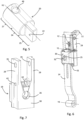
- FIG. 2 illustrates the bottom of the shell 2 and the collar 3 of the ski boot 1 without the tightening means 5.
- the locking device 10 is housed at least partially in a protrusion formed at the rear of the collar 3.
- the locking device 10 is in particular covered at least partially by an external wall 12 of the collar.
- This external wall 12 comprises an opening 50 through which the lever 11 passes, so as to remain easily accessible.
- the locking device 10 is thus protected from impacts and projections of snow or ice by the external wall 12.
- the locking device 10 comprises a mechanism 13 secured to the collar 3 and a mating element, in the form of a blade 14, secured to the bottom of the shell 2.
- the blade 14 is fixed to the bottom of the shell 2 at its lower end and projects upwards. In the ski configuration, the blade 14 is locked in position against the collar 3 by the mechanism 13, which has the effect of locking the rotational articulation between the collar and the bottom of the shell.
- the blade 14 may be a rectangular-shaped plate whose upper end is inserted into the mechanism 13.
- the blade 14 extends generally upwards, parallel to an axis Z1.
- the axis Z1 may be substantially parallel to the vertical axis Z for a given orientation of the collar 3 relative to the bottom of the shell 2.
- the Z1 axis can form a non-zero angle with the vertical Z axis. This angle is preferably less than or equal to 30°.
- the blade 14 has a curved shape, in order to ensure its good integration along a rear wall of the ski boot 1, as well as better mechanical resistance, in particular better bending resistance.
- the blade 14 could also have a rectilinear shape.
- the blade 14 comprises an upper part 15 extending in a first plane and a lower part 16 extending in a second plane parallel to the first plane and offset from the first plane.
- the first plane and the second plane may extend parallel to the vertical axis Z and to the transverse axis Y for a given inclination of the collar relative to the bottom of the shell.
- the first plane 15 is positioned further towards the front of the ski boot than the second plane 16.
- the first plane and the second plane may be connected by a bent portion.
- the angled shape of the blade 14 allows it to match the shape of the heel of the ski boot, and therefore allows for discreet and compact integration of the blade. This shape allows in particular a more downward positioning of the lower end of the blade, which makes it possible to achieve a greater amplitude of rotation of the collar relative to the bottom of the shell.
- the blade 14 is fixed to the bottom of the hull 2 according to a rotational connection around an axis of rotation Y3 parallel to the transverse axis Y.
- the bottom of the hull 2 comprises two protrusions 17, formed substantially in the area of the heel, and connected by an axis 18 extending along the axis of rotation Y3.
- the lower end of the blade 14 can be simply wrapped around said axis 18 to form said rotational connection.
- the rotational connection of the blade 14 allows the blade to follow the movement of the collar 3 when the latter pivots around the bottom of the hull 2 around the axis of rotation Y0.
- the blade 14 pivots around the axis of rotation Y3 in the frame of reference of the bottom of the hull 2, and translates along the axis Z1 in the frame of reference of the collar 3.
- the blade 14 is a single-piece metal element.
- the blade 14 can be obtained by cutting and folding a metal plate.
- the mechanism 13 comprises a housing 19 fixed to the collar 3.
- the housing 19 is provided with an opening inside which the blade 14 is engaged.
- the blade 14 is guided in translation inside the housing 19 parallel to the axis in which the blade extends, that is to say parallel to the axis Z1.
- the blade 14 is free to slide inside the housing 19 parallel to the axis Z1.
- the blade 14 is blocked inside the housing 19.
- FIG. 4 illustrates the mechanism 13 of the locking device 10, without the housing 19, the locking device being in the ski configuration. It is observed that the mechanism 13 comprises a locking element 20 movable parallel to an axis X1 between a locking position and an unlocking position.
- the axis X1 is perpendicular to the axis Z1.
- the axis X1 is perpendicular to the plane in which the upper part of the blade 14 extends, i.e. perpendicular to the first plane 15.
- the locking position of the locking element 20 corresponds to the ski configuration of the locking device 10. In the ski configuration, the locking element 20 cooperates with the blade 14 so as to prevent it from sliding within the housing 19.
- the unlocking position of the locking element 20 corresponds to the operating configuration of the locking device 10.
- the locking element 20 is then positioned relative to the blade 14 so as to allow the blade 14 to slide inside the housing 19 and thus release the rotational articulation between the collar and the bottom of the shell.
- the blade 14 comprises a stop surface intended to cooperate with the locking element 20 to lock the joint in rotation when the locking element is in the locking position.
- the locking element 20 comprises a lug
- the blade 14 comprises an opening 21 comprising a shape complementary to a shape of the lug.
- the opening 21 is a hole passing through the thickness of the blade 14.
- the upper edge 21A and the lower edge 21B of the opening 21 therefore form said stop surface cooperating with the blocking element 20 to block the articulation in rotation when the blocking element is in the blocking position.
- other shapes can be envisaged for the blocking element 20 and the opening 21.
- the locking element 20 also comprises a first guide surface 22 and the blade 14 comprises a second guide surface 23, the first guide surface 22 cooperating with the second guide surface 23 to guide the movement of the blade. 14 relative to the locking element 20 when the locking element is in the unlocked position and the collar pivots relative to the bottom of the hull.
- the locking element 20 therefore combines a function of locking the blade 14 and a function of guiding the blade 14.
- the locking device is easier to handle and more robust.
- the blade 14 is very well positioned relative to the blocking element 20 when the locking device is moved into the locking configuration. This prevents the blocking element 20 from colliding with an edge of the opening 21, which would make handling particularly delicate.
- the guide means makes it possible to provide an opening 21 in the blade whose dimensions are well adjusted to the dimensions of the blocking element 20. This makes it possible to have no play or minimal play between the collar and the bottom of the shell when the locking device is in the ski configuration.
- the blade 14 is also very well guided within the housing 19 when the locking device is in the operating configuration and the collar pivots around the bottom of the shell.
- the cooperation of the guide surfaces 22 and 23 ensures lateral guidance of the blade in the housing. This prevents the blade 14 from coming into contact with a wall of the housing 19, and more generally with any element of the mechanism 13 which would not be intended to come into contact with the blade 14.
- the locking device is thus more robust and more durable.
- a locking device does not include any guiding means between the blocking element 20 and the blade 14, the element The locking element is then positioned much less precisely relative to the blade.
- the opening provided in the blade must be larger to take into account this less precise positioning. Consequently, in the locking configuration there remains a greater clearance between the locking element and the blade, and the collar is less well locked in position relative to the bottom of the hull.
- the opening 21 may have dimensions adjusted to the dimensions of the locking element 20.
- the opening 21 does not have to be specially enlarged to allow the insertion or extraction of the locking element as is for example the case when the locking element is movable between its locking position and its unlocking position following a rotational movement or following more complex kinematics.
- the locking element 20 is illustrated in more detail in the Figure 5 . It comprises several portions along the axis X1: the locking element 20 comprises in particular a first portion 24 intended to cooperate with the opening 21 to block the rotational articulation between the collar and the bottom of the shell when the locking element is in the locking position.
- the first portion 24 may comprise a shape complementary to the shape of the opening 21, in particular a cylindrical shape whose axis of revolution is parallel to the first axis X1.
- the opening 21 comprises a circular shape whose diameter is slightly greater than the diameter of the cylindrical shape of the first portion 24 of the locking element.
- the difference in diameter between the circular shape of the opening 21 and the cylindrical shape of the first portion 24 may be, for example, less than or equal to 3 mm, preferably less than or equal to 2 mm, or even less than or equal to 1 mm.
- one end of the first portion 24 may be chamfered so as to facilitate the insertion of the first portion 24 into the opening 21.
- first portion 24 of the locking element 20 and of the opening 21 could be envisaged, for example a triangular, square, rectangular, polygonal, or ovoid shape.
- the locking element 20 and the blade 14 cooperating with the locking element could be different.
- These two elements could for example comprise reliefs, positive or negative, such as for example rack surfaces, intended to come into contact with each other when the locking element is in the locking position. More generally, the two elements can each comprise a stop surface configured to prevent the mating element from sliding in the mechanism 13 when the locking element is in the locking position.
- the locking element 20 also comprises a second portion 25 comprising said first guide surface 22.
- This second portion may comprise at least one planar face, preferably two opposite planar faces.
- the at least one planar face may extend parallel to the axis in which the blade 14 moves relative to the locking element 20, i.e. parallel to the axis Z1.
- This planar face is intended to bear against the blade 14 to guide the movement of the blade relative to the locking element.
- the second portion 25 may comprise a prismatic shape, in particular a parallelepiped shape.
- the second portion 25 may be adjacent to the first portion 24 and can be positioned further towards the front of the ski boot.
- the blade 14 comprises a groove 28.
- the groove 28 is an opening passing through the thickness of the blade and extending parallel to the axis in which the blade extends, i.e. parallel to the axis Z1.
- the groove 28 is delimited by two lateral edges extending parallel to the axis Z1.
- the length of the groove 28 along the axis Z1 is adapted as a function of the amplitude of flexion of the collar relative to the bottom of the shell when the locking device is in the operating configuration.
- Said second guide surface 23 is formed by at least one of the two edges of the groove 28, in particular by the set of the two edges, the two edges being intended to bear on the flat faces of the second portion 25 of the locking element 20.
- the distance separating the two edges of the groove 28 may be slightly greater than the width of the second portion 25 of the locking element 20 along the transverse axis Y.
- a clearance of less than or equal to 3 mm, or even less than or equal to 2 mm, or even less than or equal to 1 mm may be provided between the edges of the groove 28 and the second portion 25 of the locking element 20. This provides satisfactory guidance of the blade 14 and the latter can move relative to the locking element without excessive friction.
- the groove 28 can open onto the opening 21.
- the assembly formed by the groove 28 and the opening 21 thus forms a single opening with a closed edge, the shape of which is that of a keyhole.
- the blade 14 is thus particularly simple to manufacture.
- the blade 14 could be provided without the groove 28 and the guidance between the locking element 20 and the blade 14 could be made differently.
- the blade 14 could comprise a profiled U-shape. The wings of the U would be spaced apart by a distance slightly greater than the diameter of the locking element, so that the locking element slides between these two wings when the collar pivots relative to the bottom of the hull.
- the locking element 20 could comprise substantially the shape of an M. It would comprise a central part intended to cooperate with the opening 21 and lateral wings intended to bear on the external edges of the blade 14.
- the second portion 25 could have a different shape, for example a cylindrical shape.
- the locking element 20 could have a conical or truncated shape, the base of the conical or truncated shape forming the first portion, and the tip of the conical or truncated shape forming the second portion.
- the blade 14 could not be mobile in rotation around the axis of rotation Y3. It could then, for example, have a certain flexibility allowing the collar to pivot relative to the bottom of the hull around the axis of rotation Y0. The amplitude of rotation between the collar and the bottom of the hull could then be reduced. According to another variant, the blade 14 could be replaced by an assembly comprising several parts articulated together.
- the housing 19 comprises a guide means 26 capable of guiding the locking element 20 in translation parallel to the axis X1.
- This guide means 26 is in particular formed by a sleeve whose shape corresponds to the profiled shape of the locking element 20.
- This guide means makes it possible to properly control the translational movement. along the axis X1 of the locking element 20, and thus further limit any risk of jamming between the locking element and the blade 14.
- the locking element 20 can thus comprise a third portion 27, in particular of cylindrical shape, cooperating with the sleeve of complementary shape in the housing 19 to guide the locking element in translation parallel to the axis X1.
- a diameter of the third portion 27 could be strictly greater than a diameter of the first portion 24.
- the shoulder formed at the interface between the third portion 27 and the first portion 24 could thus come into abutment against the edge of the opening 21, which makes it possible to properly immobilize the blade 14 when the locking device is in the ski configuration.
- the locking element 20 may be a single-piece element, i.e. an element formed from a single piece.
- the locking element 20 could, for example, be made from a machined block of metal.
- the locking element could comprise several pieces fixed together; the different portions 24, 25 and 27 of the locking element could, for example, be screwed or welded together.
- the locking element 20 is made of metal, so as to withstand the significant forces that a user may exert when practicing downhill skiing.
- it could also be made of injected plastic, in particular plastic filled with glass or carbon fibers in order to increase its strength.
- the housing 19 may comprise a generally parallelepiped shape.
- the housing 19 comprises two lateral flanks 29 extending parallel to each other and connected together by a wall 30 forming a bottom of the housing.
- the wall 30 extends against the blade 14.
- the housing 19 may be made of a plastic and/or metallic material.
- the locking device comprises at least one guide, interposed between the housing 19 and the blade 14, configured to guide the sliding of the blade 14 relative to the housing 19.
- the at least one guide may comprise a material with non-stick properties, for example plastic filled with fibers, for example filled with PTFE.
- the at least one guide may be an independent part of the housing, or alternatively, be directly formed in the housing.
- the at least one guide comprises two guides 31 each cooperating with a lateral edge of the blade 14.
- the guides 31 are arranged on either side of the blade 14, inside the opening of the housing 19 inside which the blade 14 slides.
- the guides 31 may each comprise shoulders bearing against edges of the housing so as to maintain the guides in position relative to the housing.
- the wall 30 of the housing may advantageously comprise a second opening 32 intended to receive one end of the locking element 20, in particular the second portion 25 of the locking element 20, when the latter is in the locking position.
- the locking element 20 is supported both by the guide means 26 of the housing 19 and by the edge of the second opening 32.
- the locking element 20 is thus supported on either side of the blade 14.
- the significant forces exerted by the user on the collar are transmitted to the interface between the locking element 20 and the blade 14.
- the support of the locking element 20 on either side of the blade 14 makes it possible to maintain a stable position of the locking element 20.
- the locking element 20 therefore does not become skewed under the effect of the significant force exerted by the user. It therefore does not risk being damaged. This avoids subjecting the mechanism 13 to the forces generated by the user.
- the second opening 32 may possibly have a shape complementary to the shape of said second portion 25 of the locking element 20.
- the lever 11 is particularly clearly visible on the Figure 4 .
- the lever 11 comprises a wing 33 projecting towards the rear of the ski boot.
- the wing 33 is intended to be manipulated by the user of the ski boot.
- the lever 11 also comprises a shaft 34 extending parallel to the transverse axis Y.
- the shaft 34 cooperates with a first pair of openings 35 formed in the lateral flanks 29 of the housing 19.
- the shaft 34 is in the form of two generally cylindrical studs projecting on either side of a body 51 of the lever 11. The lever 11 is thus movable in rotation relative to the housing 19 around an axis of rotation Y2 parallel to the transverse axis Y.
- the body 51 of the lever 11 comprises at least one wall, preferably two walls 52A, 52B of generally cylindrical shape whose axis of revolution corresponds to the axis of rotation Y2.
- the walls 52A, 52B are positioned respectively above and below the wing 33.
- the walls 52A, 52B are positioned opposite the opening 50 formed in the collar 3 regardless of the position of the lever 11. More precisely, the wall 52A is positioned opposite the opening 50 when the lever 11 is in the lowered position.
- the wall 52B is positioned opposite the opening 50 when the lever 11 is in the raised position.
- the walls 52A, 52B thus prevent snow, water or any other form of particle from entering the interior of the ski boot by passing through the opening 50.
- the shaft 34 could be held not by the housing 19 but directly by the collar 3.
- the dimensions of the housing 19 could be reduced.
- the lateral flanks 29 of the housing could be removed.
- the shaft 34 can then be a separate element from the body 51 of the lever 11. The shaft 34 can then be inserted transversely through the openings provided in the collar 3 for this purpose and through the body of the lever 11.
- the lever 11 also comprises stop surfaces 36, 37, intended to cooperate with walls of the collar 3 to limit the amplitude of rotation of the lever around the axis of rotation Y2.
- a first stop surface 36 bears against a wall of the collar when the locking element is in the locking position.
- a second stop surface 37 bears against a wall of the collar when the locking element is in the unlocking position.
- the lever 11 may be a monolithic element, for example manufactured by plastic injection.
- a body of the lever comprising the wing 33 and the abutment surfaces 36, 37 may be a monolithic element, this monolithic element comprising an opening inside which the shaft 34 is inserted.
- the lever 11 could still be manufactured differently and/or result from the assembly of several parts fixed together so as to form a single-piece assembly.
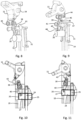
- the mechanism 13 makes it possible to move the locking element 20 between its locking position and its unlocking position in a particularly advantageous manner. This mechanism 13 will now be described in more detail with reference to figures 8 to 11 .
- the mechanism 13 comprises a rocker 38 mounted to rotate about an axis of rotation Y1.
- the axis of rotation Y1 is parallel to the transverse axis Y.
- the rocker 38 comprises a first portion 39 extending above the axis of rotation Y1 and a second portion 40 extending below the axis of rotation Y1.
- the rocker pivots in a first direction about the axis of rotation Y1
- the first portion 39 moves forward and the second portion 40 moves rearward.
- the rocker pivots in a second direction about the axis of rotation Y1, opposite to the first direction
- the first portion 39 moves rearward and the second portion 40 moves forward.
- the rotation axis Y1 extends substantially halfway up the rocker 38 along the vertical axis Z. However, this position of the rotation axis Y1 can be adjusted so as to adapt the leverage effect produced by the rocker 38.
- the mechanism 13 comprises a shaft 41 extending along said rotation axis Y1 between the two lateral flanks 29 of the housing.
- the shaft 41 extends between a second pair of openings 42 provided in the lateral flanks 29, in particular below the first pair of openings 35.
- the shaft is thus supported by the housing 19.
- the shaft 41 also passes through a central opening provided in the rocker 38.
- the rotational movement of the rocker 38 about the rotation axis Y1 can be obtained by a relative rotation between the rocker 38 and the shaft 41 and/or by a relative rotation between the shaft 41 and the housing 19.
- the shaft 41 advantageously comprises securing means, in particular widened ends, configured to hold the shaft 41 securely to the housing 19.
- the widened end can for example be formed by crimping.
- the shaft 41 could be made of two parts assembled together, each part comprising an enlarged portion.
- the rocker 38 interacts with the lever 11 by means of a return means, in particular a torsion spring 43.
- the torsion spring 43 comprises a first end 44 in contact with a bearing surface 45 of the lever 11, and a second end 46, opposite its first end 44, in contact with a first bearing surface 47 of the rocker 38.
- the bearing surface 45 of the lever 11 takes the form of a U-shaped housing, profiled along the transverse axis Y, and inside which the first end 44 of the torsion spring 43 is placed.
- the first end 44 is thus well held and secured against the lever 11.
- the first bearing surface 47 of the rocker 38 takes the form of an opening passing through the first portion 39 of the rocker. It is therefore understood that the lever 11 is thus configured to exert pressure against the first bearing surface 47 of the rocker 38, and thus cause the rocker 38 to pivot around the axis of rotation Y1.
- the torsion spring 43 comprises a set of coils defined around an axis parallel to the transverse axis Y.
- the torsion spring 43 is intended to be stressed in torsion.
- the maximum compression state of the torsion spring is reached when the distance separating the bearing surfaces 45 and 47 is minimal. This configuration can be reached when the bearing surfaces 45 and 47 are aligned with the axes of rotation Y1 and Y2.
- the torsion spring 43 is thus configured so as to be put under tension transiently when the lever is moved between its locking position and its unlocking position.
- the locking and unlocking positions of the lever correspond to states of lesser tension of the torsion spring 38 and are therefore stable positions.
- the rocker 38 further comprises a second bearing surface 48 opposite the first bearing surface 47 with respect to the axis of rotation Y1.
- the second bearing surface 48 is configured to exert pressure against the locking element 20 to move the locking element between its locking position and its unlocking position. More precisely, the lower end of the rocker 38 is engaged in a recess 49 formed in the locking element.
- the second bearing surface 48 therefore corresponds to the end of the rocker 38 pressed into the recess 49.
- the recess 49 can advantageously be formed in the third portion 27 of the locking element 20.
- the recess 49 can be for example a blind hole of cylindrical shape.
- the edges of the recess 49 can be flared so as to facilitate the pivoting movement of the rocker 38.
- the rocker 38 could comprise a rounded toothed portion, provided with a plurality of teeth extending radially, and the locking element could comprise a rack portion cooperating with the rounded toothed portion.
- the locking element could comprise a protrusion projecting from a cylindrical body of the locking element 20 and the lower end of the rocker could comprise a recess cooperating with this protrusion.
- the locking device 10 operates as follows.
- the user wishes to switch from the ski configuration to the walking configuration, he lowers the lever 11 by pivoting it around the axis of rotation Y2.
- the bearing surface 45 of the lever 11 moves towards the front of the ski boot, which tends to bring the bearing surface 45 closer to the first bearing surface 47 of the rocker 38.
- the torsion spring 43 is tensioned until it reaches a maximum tension value corresponding approximately to the halfway point of the lever between its raised position and its lowered position. Then, the bearing surface 45 moves away again from the first bearing surface and the tension of the torsion spring 43 decreases again.
- the torsion spring 43 transmits the force imparted on the lever 11 to the rocker 38.
- the first portion 39 of the rocker 38 moves forward.
- the second portion 40 of the rocker 38 moves rearward.
- the second bearing surface 48, arranged on the second portion 40 of the rocker then exerts a rearward pressure on the locking element 20.
- the locking element 20 is then moved rearward, that is to say from its locking position to its unlocking position.
- In the unlocked position it is the second portion 25 of the locking element 20 which is positioned in the opening 21 formed in the blade 14.
- the second portion 25 can slide in the groove 28 of the blade.
- the locking element 20 does not prevent the blade 14 from translating inside the housing.
- the articulation between the collar and the bottom of the shell is thus released. The user can then comfortably walk with the ski boot.
- the collar pivots relative to the bottom of the shell which induces back and forth movements of the blade within the housing.
- This back and forth movement is guided both by the cooperation of the guide surfaces 22 and 23, and by the cooperation of the two guides 31 with the edges of the blade 14.
- the locking element 20 remains very well positioned relative to the blade 14 during walking, which subsequently facilitates a new locking operation of the locking device.
- This locking operation is carried out in a similar manner by raising the lever 11 upwards. In doing so, the first portion 24 of the locking element is positioned in the opening 21 of the blade, and the second portion 25 is positioned in the second opening 32 formed in the wall 30 of the housing.
- the precise adjustment between the locking element 20 and the opening 21 makes it possible to effectively lock and firmly the rotating joint between the collar and the bottom of the shell. The user thus benefits from a rigid ski boot, efficiently transmitting his impulses for alpine skiing.
- a locking device 10 is provided that is particularly effective and ergonomic to use.
- the locking device comprises a limited number of components. It is therefore simple to manufacture, compact and lightweight.
Landscapes
- Health & Medical Sciences (AREA)
- General Health & Medical Sciences (AREA)
- Physical Education & Sports Medicine (AREA)
- Footwear And Its Accessory, Manufacturing Method And Apparatuses (AREA)
Priority Applications (2)
| Application Number | Priority Date | Filing Date | Title |
|---|---|---|---|
| EP23425062.9A EP4555889A1 (de) | 2023-11-20 | 2023-11-20 | Verriegelungsvorrichtung für einen sportschuh |
| US18/951,823 US20250160477A1 (en) | 2023-11-20 | 2024-11-19 | Locking device for a ski boot |
Applications Claiming Priority (1)
| Application Number | Priority Date | Filing Date | Title |
|---|---|---|---|
| EP23425062.9A EP4555889A1 (de) | 2023-11-20 | 2023-11-20 | Verriegelungsvorrichtung für einen sportschuh |
Publications (1)
| Publication Number | Publication Date |
|---|---|
| EP4555889A1 true EP4555889A1 (de) | 2025-05-21 |
Family
ID=89771779
Family Applications (1)
| Application Number | Title | Priority Date | Filing Date |
|---|---|---|---|
| EP23425062.9A Pending EP4555889A1 (de) | 2023-11-20 | 2023-11-20 | Verriegelungsvorrichtung für einen sportschuh |
Country Status (1)
| Country | Link |
|---|---|
| EP (1) | EP4555889A1 (de) |
Citations (4)
| Publication number | Priority date | Publication date | Assignee | Title |
|---|---|---|---|---|
| EP0149445A1 (de) * | 1983-12-22 | 1985-07-24 | Koflach Sportgeräte Gesellschaft m.b.H | Schischuh mit einer Schale und einem relativ zu dieser Schale verschwenkbaren Schaftteil |
| US4962595A (en) * | 1988-09-09 | 1990-10-16 | Koflach Sport Gesellschaft M.B.H. & Co. Kg | Ski shoe |
| US5101581A (en) * | 1989-12-18 | 1992-04-07 | Dynafit Skischuh Gesellschaft M.B.H. | Damping element for ski boots |
| US5408762A (en) * | 1991-12-02 | 1995-04-25 | Dynafit Skischuh Gesellschaft M.B.H. | Adjustment system for ski boots having an articulated collar |
-
2023
- 2023-11-20 EP EP23425062.9A patent/EP4555889A1/de active Pending
Patent Citations (4)
| Publication number | Priority date | Publication date | Assignee | Title |
|---|---|---|---|---|
| EP0149445A1 (de) * | 1983-12-22 | 1985-07-24 | Koflach Sportgeräte Gesellschaft m.b.H | Schischuh mit einer Schale und einem relativ zu dieser Schale verschwenkbaren Schaftteil |
| US4962595A (en) * | 1988-09-09 | 1990-10-16 | Koflach Sport Gesellschaft M.B.H. & Co. Kg | Ski shoe |
| US5101581A (en) * | 1989-12-18 | 1992-04-07 | Dynafit Skischuh Gesellschaft M.B.H. | Damping element for ski boots |
| US5408762A (en) * | 1991-12-02 | 1995-04-25 | Dynafit Skischuh Gesellschaft M.B.H. | Adjustment system for ski boots having an articulated collar |
Similar Documents
| Publication | Publication Date | Title |
|---|---|---|
| EP2687275B1 (de) | Vordere Haltevorrichtungen eines Gleitbrettes | |
| EP3260178B1 (de) | Fersenhalter zur befestigung eines schuhes auf einem snowboard | |
| EP0248149A1 (de) | Schischuh | |
| EP2769755B1 (de) | Vordere Halteeinrichtung mit automatischer Auslösung bei Verdrehung | |
| EP1935461B1 (de) | Mit einem mindestens zwischen zwei Positionen hin und her schaltbaren, beweglichen Knopf ausgestatteter Artikel | |
| FR2788444A1 (fr) | Fixation declenchable pour planche de glisse | |
| EP0712647B1 (de) | Haltevorrichtung für Skischuhe auf Gleitbrettern | |
| EP0105011A1 (de) | Skischuh mit eingebauter Multirichtstrahlbindung | |
| EP0193686B1 (de) | Rückhaltevorrichtung für einen Schuh auf einem Ski | |
| EP4670549A1 (de) | Verriegelungsvorrichtung für einen skischuh | |
| FR2493711A1 (fr) | Retenue de talon pour une fixation de securite de ski | |
| FR2598934A1 (fr) | Fixation de securite d'une chaussure sur un ski | |
| CH652936A5 (fr) | Fixation de securite pour ski. | |
| FR2492670A1 (fr) | Dispositif de verrouillage pour une fixation de ski utilisee en randonnee et en descente | |
| EP4397203B1 (de) | Verriegelungsvorrichtung für einen sportschuh | |
| EP1526900A2 (de) | Bindung mit integrierten einhaksystem | |
| EP4397202A1 (de) | Verriegelungsvorrichtung für einen sportschuh | |
| FR3144908A1 (fr) | Dispositif de verrouillage pour une chaussure de sport | |
| FR2501052A1 (fr) | Fixation de securite de ski | |
| FR2523461A1 (fr) | Fixation de securite pour ski | |
| CH656542A5 (fr) | Fixation de securite pour ski. | |
| FR2738156A1 (fr) | Dispositif de fixation et de deverrouillage automatique | |
| CH669120A5 (fr) | Frein de ski. | |
| FR2870750A1 (fr) | Dispositif de retenue et de reglage en position longitudinale d'une fixation sur une planche de glisse sur neige | |
| FR3145097A1 (fr) | Fixation pour ski nordique |
Legal Events
| Date | Code | Title | Description |
|---|---|---|---|
| PUAI | Public reference made under article 153(3) epc to a published international application that has entered the european phase |
Free format text: ORIGINAL CODE: 0009012 |
|
| STAA | Information on the status of an ep patent application or granted ep patent |
Free format text: STATUS: THE APPLICATION HAS BEEN PUBLISHED |
|
| AK | Designated contracting states |
Kind code of ref document: A1 Designated state(s): AL AT BE BG CH CY CZ DE DK EE ES FI FR GB GR HR HU IE IS IT LI LT LU LV MC ME MK MT NL NO PL PT RO RS SE SI SK SM TR |
|
| STAA | Information on the status of an ep patent application or granted ep patent |
Free format text: STATUS: REQUEST FOR EXAMINATION WAS MADE |
|
| 17P | Request for examination filed |
Effective date: 20251118 |