EP0712740A2 - Verfahren und Vorrichtung zur Berechnung des Lenkradius eines Fahrzeuges unter Berücksichtigung seiner Belastungsbewegung - Google Patents
Verfahren und Vorrichtung zur Berechnung des Lenkradius eines Fahrzeuges unter Berücksichtigung seiner Belastungsbewegung Download PDFInfo
- Publication number
- EP0712740A2 EP0712740A2 EP95118003A EP95118003A EP0712740A2 EP 0712740 A2 EP0712740 A2 EP 0712740A2 EP 95118003 A EP95118003 A EP 95118003A EP 95118003 A EP95118003 A EP 95118003A EP 0712740 A2 EP0712740 A2 EP 0712740A2
- Authority
- EP
- European Patent Office
- Prior art keywords
- vehicle
- tire
- turning radius
- rotational angular
- tires
- Prior art date
- Legal status (The legal status is an assumption and is not a legal conclusion. Google has not performed a legal analysis and makes no representation as to the accuracy of the status listed.)
- Granted
Links
- 238000000034 method Methods 0.000 title claims abstract description 32
- 238000005096 rolling process Methods 0.000 claims abstract description 76
- 230000001133 acceleration Effects 0.000 claims description 119
- 238000012937 correction Methods 0.000 claims description 83
- 230000005484 gravity Effects 0.000 claims description 11
- 238000001514 detection method Methods 0.000 claims description 10
- 108010063499 Sigma Factor Proteins 0.000 claims description 3
- 230000002401 inhibitory effect Effects 0.000 claims 2
- 238000012545 processing Methods 0.000 description 28
- 238000004364 calculation method Methods 0.000 description 16
- 238000010276 construction Methods 0.000 description 5
- 238000010586 diagram Methods 0.000 description 4
- 238000005070 sampling Methods 0.000 description 4
- 230000007423 decrease Effects 0.000 description 3
- 238000012986 modification Methods 0.000 description 3
- 230000004048 modification Effects 0.000 description 3
- 238000012360 testing method Methods 0.000 description 3
- 238000006243 chemical reaction Methods 0.000 description 1
- 230000003247 decreasing effect Effects 0.000 description 1
- 238000009795 derivation Methods 0.000 description 1
- 239000007788 liquid Substances 0.000 description 1
Images





Classifications
-
- B—PERFORMING OPERATIONS; TRANSPORTING
- B62—LAND VEHICLES FOR TRAVELLING OTHERWISE THAN ON RAILS
- B62D—MOTOR VEHICLES; TRAILERS
- B62D6/00—Arrangements for automatically controlling steering depending on driving conditions sensed and responded to, e.g. control circuits
- B62D6/04—Arrangements for automatically controlling steering depending on driving conditions sensed and responded to, e.g. control circuits responsive only to forces disturbing the intended course of the vehicle, e.g. forces acting transversely to the direction of vehicle travel
-
- B—PERFORMING OPERATIONS; TRANSPORTING
- B60—VEHICLES IN GENERAL
- B60T—VEHICLE BRAKE CONTROL SYSTEMS OR PARTS THEREOF; BRAKE CONTROL SYSTEMS OR PARTS THEREOF, IN GENERAL; ARRANGEMENT OF BRAKING ELEMENTS ON VEHICLES IN GENERAL; PORTABLE DEVICES FOR PREVENTING UNWANTED MOVEMENT OF VEHICLES; VEHICLE MODIFICATIONS TO FACILITATE COOLING OF BRAKES
- B60T8/00—Arrangements for adjusting wheel-braking force to meet varying vehicular or ground-surface conditions, e.g. limiting or varying distribution of braking force
- B60T8/17—Using electrical or electronic regulation means to control braking
- B60T8/172—Determining control parameters used in the regulation, e.g. by calculations involving measured or detected parameters
-
- B—PERFORMING OPERATIONS; TRANSPORTING
- B60—VEHICLES IN GENERAL
- B60C—VEHICLE TYRES; TYRE INFLATION; TYRE CHANGING; CONNECTING VALVES TO INFLATABLE ELASTIC BODIES IN GENERAL; DEVICES OR ARRANGEMENTS RELATED TO TYRES
- B60C23/00—Devices for measuring, signalling, controlling, or distributing tyre pressure or temperature, specially adapted for mounting on vehicles; Arrangement of tyre inflating devices on vehicles, e.g. of pumps or of tanks; Tyre cooling arrangements
- B60C23/06—Signalling devices actuated by deformation of the tyre, e.g. tyre mounted deformation sensors or indirect determination of tyre deformation based on wheel speed, wheel-centre to ground distance or inclination of wheel axle
- B60C23/061—Signalling devices actuated by deformation of the tyre, e.g. tyre mounted deformation sensors or indirect determination of tyre deformation based on wheel speed, wheel-centre to ground distance or inclination of wheel axle by monitoring wheel speed
Definitions
- the present invention relates to a method of and a device for calculating a turning radius of a vehicle.
- the turning radius of a vehicle is, for example, a curvature radius of the path swept out by the center of gravity of the vehicle.
- the turning radius of a vehicle is utilized for a tire pressure drop detecting device which has been developed for the purpose of securing safety of the vehicle, Anti-lock Braking System (ABS) or Navigation System.
- ABS Anti-lock Braking System
- a method of determining the turning radius of a vehicle is classified roughly into two types.
- the one is a method of utilizing an output of a steering angle sensor.
- the other is a method of utilizing the respective rotational angular velocities F1, F2, F3 and F4 of four tires provided for the vehicle.
- the tires W1 and W2 are right font and left front tires, respectively.
- the tires W3 and W4 are right rear and left rear tires, respectively.
- the rotational angular velocity F i (i is 1, 2, 3 or 4) varies depending on the right or left tire W i when the vehicle is traveling at a corner or curve (hereinafter represented by the "corner").
- the rotational angular velocity F i of the tire W i which is located on the inside to the corner is relatively small, and the rotational angular velocity F i of the tire W i on the outside is relatively large, because there is a difference between the turning radius of the tire W i on the inside of the corner and that of the tire W i on the outside of the corner. Accordingly, the turning radius of the vehicle can be determined by utilizing each rotational angular velocity F i of right and left tires.
- equation (1) represents that F1 and F3 as well as F2 and F4 can be exchanged, respectively.
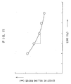
- Fig. 11 is a graph showing the relationship between the load exerted on the tire W i and effective rolling radius of the tire W i .
- the effective rolling radius is a value obtained by dividing by 2 ⁇ a travel distance of the vehicle while the tire makes one free revolution. As is apparent from the graph shown in Fig. 11, the effective rolling radius of the tire W i decreases as the load exerted on the tire W i increases.
- the rotational angular velocity F i of the tire W i varies depending on the effective rolling radius of the tire W i . That is, if the speed of the vehicle is constant, the rotational angular velocity F i becomes large when the effective rolling radius of the tire W i becomes small. Consequently, the rotational angular velocity F i of the tire W i is influenced by not only difference in turning radius between inner and outer wheels, but also load movement of the vehicle, at the time of cornering. Therefore, the turning radius R calculated by the above formula (1) is a value influenced by the load movement of the vehicle and is not an accurate value.
- the first object of the present invention is to provide a method capable of calculating a turning radius of a vehicle, accurately, regardless of the load movement of the vehicle.
- the second object of the present invention is to provide a device capable of calculating a turning radius of a vehicle, accurately, without being influenced by the load movement of the vehicle.
- the third object of the present invention is to provide a tire pressure drop detecting method, utilizing a turning radius of a vehicle calculated, accurately, without being influenced by the load movement of the vehicle.
- the fourth object of the present invention is to provide a tire pressure drop detecting device, utilizing a turning radius of a vehicle calculated, accurately, without being influenced by the load movement of the vehicle.
- the turning radius of the vehicle having left and right tires can be determined.
- the rotational angular velocities of the left and right tires are detected.
- the turning radius of the vehicle is determined, on the basis of this detected rotational angular velocities, by taking a change in effective rolling radiuses due to the load movement of the vehicle into consideration. Thereby, the turning radius of the vehicle can be calculated, accurately, without being influenced by the load movement of the vehicle.
- the lateral acceleration of the vehicle may be detected.
- an influence of the change in effective rolling radiuses of tires due to the load movement of the vehicle on the rotational angular velocities is excluded on the basis of the detected lateral acceleration of the vehicle.
- the load movement of the vehicle is proportional to the lateral acceleration of the vehicle so that the turning radius of the vehicle in which the influence of the load movement of the vehicle is excluded, is calculated by taking the lateral acceleration into consideration.
- a correction factor may be determined on the basis of the load of the vehicle to exclude the influence of the change in effective rolling radiuses of tires due to the load movement of the vehicle on the rotational angular velocities, using the resulting correction factor and lateral acceleration of the vehicle.
- a constant corresponding to the load of the vehicle may be used, but it is preferred to detect the load of the vehicle thereby determining the correction factor on the basis of this detected value.
- the correction factor can be renovated according to the load of the vehicle.
- the load of the vehicle varies depending on the numbers of persons in the vehicle and quantity of the baggage in the vehicle, thereby changing the load to be moved. Accordingly, there can be obtained the turning radius of the vehicle without the influence of the load movement of the vehicle, more certainly, by detecting the load of the vehicle each time.
- the speeds of the left and right tires may be determined by multiplying the detected rotational angular velocities by a constant corresponding to the effective rolling radius of the tire at the time of linear traveling to correct the resulting speeds of right and left tires so as to exclude the influence of a change in effective rolling radius of the tire due to the load movement of the vehicle on rotational angular velocities.
- the turning radius of the vehicle is determined on the basis of the corrected speeds of right and left tires.
- the first vehicle turning radius R' in which an influence due to the load movement of the vehicle is not taken into consideration may be determined on the basis of the detected rotational angular velocities to determine the second vehicle turning radius R, which is not influenced by the load movement of the vehicle, by correcting the resulting first vehicle turning radius R' taking the influence of the change in effective rolling radiuses of tires due to the load movement of the vehicle into consideration.
- a correction factor may be determined on the basis of the load of the vehicle to exclude the influence of the change in effective rolling radiuses of tires due to the load movement of the vehicle on the rotational angular velocities, using the resulting correction factor. In this case, it is preferred to detect the load of the vehicle.
- the speeds of right and left tires are determined by multiplying the detected rotational angular velocities by a constant corresponding to the effective rolling radius of the tire at the time of linear traveling, to calculate the first vehicle turning radius R' on the basis of the resulting speeds of right and left tires.
- VI 3 is the speed of the left tire, determined by multiplying the detected rotational angular velocity by the constant corresponding to the effective rolling radius of the tire at the time of linear traveling
- VI4 is the speed of the right tire, determined by multiplying the detected rotational angular velocity by the constant corresponding to the effective rolling radius of the tire at the time of linear traveling.
- the lateral acceleration of the vehicle is proportional to the square of the speed of the vehicle. Therefore, (V14 + V13)2 in the above formula can be said to be a term corresponding to the lateral according to the vehicle. Accordingly, the first vehicle turning radius R' can be corrected by taking the lateral acceleration of the vehicle into consideration according to the above formula. And besides, it is unnecessary to detect the lateral acceleration of the vehicle, directly.
- the detected rotational angular velocities of right and left tires may be corrected so as to exclude the influence of the change in effective rolling radiuses of the tires due to the load movement of the vehicle on the rotational angular velocities to calculate the turning radius on the basis of the resulting corrected rotational angular velocities of right and left tires.
- the left and right tires are following tires which follow along as the vehicle moves on the ground surface.
- the rotational radius can be accurately calculated by utilizing the rotational angular velocities of the following tires without taking the generation of a slip into consideration. Therefore, it is possible to make the processing simple.
- the turning radius of the vehicle in which the influence of the change in effective rolling radiuses of the tires due to the load movement of the vehicle is excluded, thus obtained as described above may be utilized for the judgment whether the pneumatic pressure of the tires provided for the vehicle drops or not. More concretely, it may be detected whether any tire provided for the vehicle causes a pressure drop or not, under the condition that the turning radius is larger than a predetermined value. In this case, it is preferred to inhibit the detection of the tire pressure drop, if the turning radius of the vehicle is smaller than the predetermined value.
- the turning radius of the vehicle can be used, for example, for judging whether the vehicle is traveling linearly or traveling at a corner. Since the vehicle can cause a linear slip when traveling at the severe corner, the tire pressure drop is not likely to be detected, accurately. Therefore, the tire pressure drop can be appropriately detected by deciding whether or not the tire pressure drop should be detected based on whether or not the turning radius of the vehicle is large. In this case, when using the turning radius in which the influence of the load movement on the vehicle is excluded, it is possible to carry out the judgment whether the tire pressure drop should be detected or not, accurately.
- the above detected rotational angular velocities may be corrected by using the turning radius of the vehicle, in which the influence of a change in effective rolling radiuses of the tires due to the load movement of the vehicle, to determine the rotational angular velocities wherein scatter of the rotational angular velocities caused by a difference in inner and outer wheels between the left and right tires is excluded. It may also be judged whether any tire causes the pressure drop or not, on the basis of the resulting rotational angular velocities Thereby, the tire pressure drop can be detected, satisfactory.
- the tire whose pneumatic pressure drops may also be specified on the basis of the above corrected rotational angular velocities. Thereby, the tire whose pneumatic pressure drops can be accurately specified.
- Fig. 1 is a block diagram showing the fundamental construction of a tire pressure drop detecting device to which one embodiment of the present invention is applied.
- Fig. 2 is a block diagram showing the electrical construction of a tire pressure drop detecting device.
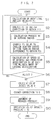
- Fig. 3 is a flow chart for explaining the detection processing of the tire pressure drop.
- Fig. 4 is an illustration for explaining a lateral acceleration exerted on the vehicle.
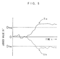
- Fig. 5 is a graph for explaining the judging method of the tire pressure drop.
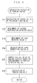
- Fig. 6 is a flow chart for explaining the calculation processing of the turning radius according to the first embodiment of the present invention.
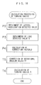
- Fig. 7 is a flow chart for explaining the calculation processing of the turning radius according to the second embodiment of the present invention.
- Fig. 8 is a graph showing the test results which illustrate that the influence of the load movement of the vehicle is excluded in the turning radius calculated by the calculation processing of the turning radius in the second embodiment.
- Fig. 9 is a flow chart for explaining the calculation processing of the turning radius according to the modification of the second embodiment of the present invention.
- Fig. 10 is a flow chart for explaining the calculation processing of the turning radius according to the third embodiment of the present invention.
- Fig. 11 is a graph showing the relationship between the load exerted on a tire and effective rolling radius of the tire.
- Fig. 1 is a block diagram showing the fundamental construction of a tire pressure drop detecting device to which one embodiment of the present invention is applied.
- This tire pressure drop detecting device detects whether the pneumatic pressures of four tires W1, W2, W3 and W4 provided for a four-tire vehicle drop or not, respectively.
- the tires W1 and W2 correspond to right front and left front tires
- the tires W3 and W4 correspond to right rear and left rear tires, respectively.
- these tires may be referred to as a "tire W i " hereinafter.
- the tires W1, W2, W3 and W4 are associated with a wheel speed sensors 1 serving as rotational angular velocity detecting means, respectively. Output signals of each of the wheel speed sensor 1 are supplied to a control unit 2.
- a lateral acceleration sensor 3, a load sensor 4 and an indicator 5 are connected to the control unit 2.
- the lateral acceleration sensor 3 serves as lateral acceleration detecting means for detecting a lateral acceleration of the vehicle.
- the load sensor 4 serves as load detecting means for detecting a load of the vehicle.
- the indicator 5 is used to inform the tire W i whose pneumatic pressure possibly drops and may be constructed in forms of a liquid display element, a plasma display element or CRT.
- control unit 2 corresponds to the turning radius operating means.
- Fig. 2 is a block diagram showing the electrical construction of a tire pressure drop detecting device.
- the control unit 2 is composed of a micro computer including an I/O interface 2a, a CPU 2b, a ROM 2c and a RAM 2d.
- the I/O interface 2a is used to send and receive signals to and from an external device.
- the CPU 2b serves as the center of operation processing.
- a control operation program of the CPU 2b is stored in the ROM 2c. Data, etc. are temporarily written to or the written data are read out from the RAM 2d when the CPU 2b performs a control operation.
- Each of the wheel speed sensor 1 generates pulse signals corresponding to the rotating speed of the corresponding tire W i (hereinafter referred to as a "wheel speed pulse").
- Fig. 3 is a flow chart for explaining the detection processing of tire pressure drop, which is performed by the control unit 2.
- This processing is realized by a software processing.
- the explanation will be made with respect to an FF (front engine-front drive) vehicle as the objective vehicle. That is, right front and left front tires W1 and W2 are driving tires which rotate actively by applying a driving force from the engine. In addition, right rear and left rear tires W3 and W4 are following tires rolling on the ground surface as the vehicle moves.
- FF front engine-front drive
- the rotational angular velocity F i of each tire W i is firstly calculated on the basis of the wheel speed pulse generated from each wheel speed sensor 1 (step S1).
- the effective rolling radius is a value obtained by dividing by 2 ⁇ a travel distance of the vehicle while the tire makes one free revolution.
- the constant r corresponding to the effective rolling radius when the vehicle is traveling linearly is previously stored in the ROM 2c.
- the calculated rotational angular velocities are corrected so as to exclude scatter due to the initial difference (step S2).
- the calculations according to the following equations (2) to (5) are carried out to determine rotational angular velocities F11, F12, F13 and F14 after initial correction.
- F1 1 F 1 (3)
- F1 2 aF 2 (4)
- F1 3 F 3 (5)
- F1 4 bF 4
- the correction factors a and b are, for example, determined when the vehicle travels at the first time, when the tire W i is filled with air or when the tire W i is replaced, and they are previously stored in the ROM 2c of the control unit 2.
- the rotational angular velocities F i of the tires W i vary depending on the above initial difference and is also influenced by the difference in inner and outer wheels and load movement of the vehicle.
- the inner and outer tires differ in rotational angular velocity because of a difference between the turning radius of the tire W i on the inside of a corner or curve (hereinafter represented by the "corner") and that of the tire W i on the outside of the corner (hereinafter referred to as a "tire turning radius difference”) when the vehicle is traveling at the corner or curve.
- the corner the turning radius of the tire W i on the inside of a corner or curve
- tire turning radius difference that of the tire W i on the outside of the corner
- the rotational angular velocities vary between inner and outer tires due to the influence of the load movement of the vehicle.
- Q1 is a counterforce (kgf) from the ground surface to a partial load exerted on the tire W3 among the load Q of the vehicle (hereinafter referred to as a "load counterforce")
- H is a height (m) of gravity O of the vehicle from the ground surface of the center
- Lateral acceleration takes a positive value when it exerts in the direction from the left tire W3 to the right tire W4, and takes a negative value when it exerts on the direction from the right tire W4 to the left tire W3.
- the rotational angular velocities F i vary with inner and outer tires due to the tire turning radius difference and, at the same time, the rotational angular velocities F i of inner and outer tires are influenced corresponding to the above formulas (14) and (15), respectively, because of a change in effective rolling radiuses of the tires W i due to the load movement of the vehicle.
- the turning radius R of the vehicle in which the influence of the load movement of the vehicle is excluded is firstly calculated (step S3) in the turning radius calculation processing described hereinafter.
- the rotational angular velocities F1 i after initial correction calculated in the above step S2 are corrected, on the basis of the above calculated turning radius R, so as to exclude scatter caused by the tire turning radius difference (step S4).
- (R-Tw/2) 2 +WB 2 ⁇ F1 1 (17) F2 2
- (R+Tw/2) 2 +WB 2 ⁇ F1 2 (18) F2 3
- ⁇ F1 3 (19) F2 4
- a rotating angular velocities F2 i in which scatter caused by the tire turning radius difference are excluded can be obtained. That is, the rotational angular velocities F21, F22, F23 and F24 become almost the same values which correspond to the speed of the
- WB is a wheel base of the vehicle.
- the correction according to the above equations (16) to (19) is a processing performed on the assumption that the vehicle is an FF vehicle, as described above. If the vehicle is an FR (front engine-rear drive) vehicle, the correction is performed according to the following equations (20) to (23). In this case, the front tires W1 and W2 are following tires, and the rear tires W3 and W4 are driving tires.
- F2 1
- ⁇ F1 1
- F2 2
- ⁇ F1 2
- F2 3
- F2 4
- the above rotational angular velocities F i sometimes contain an error depending on the turning radius R of the vehicle, speed V of the vehicle, rear/front acceleration of each tire W i and magnitude of the lateral acceleration.
- the speed V2 of the vehicle and rear/front acceleration G i of each tire W i are calculated and, at the same time, the lateral acceleration of the vehicle is obtained from the lateral acceleration sensor 3 (step S5). More concretely, the speed V2 of the vehicle is calculated on the basis of the speed V2 i of each tire W i .
- the speed V2 i of each tire W i is calculated according to the following equation (24). In the following equation (24), r is a constant corresponding to the effective rolling radius of the tire W i at the time of linear traveling and is used after reading out from the ROM 2c.
- V2 i r x F2 i
- V2 (V2 1 + V2 2 + V2 3 + V2 4 )/4
- the rear/front acceleration G i of each tire W i is calculated according to the following equation (26) letting the speed of each tire W i calculated in the previous sampling period be BV2 i .
- the numeral 9.8 is inserted in the denominator in the following equation (26) so as to subject the rear/front acceleration G i of each tire W i to gravity acceleration conversion.
- ⁇ T is a sampling period time.
- Rear/front acceleration G i (V2 i - BV2 i )/( ⁇ x 9.8)
- the above speed V2 of the vehicle and rear/front acceleration G i of each tire W i may be determined, for example, using outputs of sensors respectively capable of directly detecting the vehicle speed V2 and rear/front acceleration G i .
- step S6 On the basis of the turning radius R of the vehicle, speed V2 of the vehicle, rear/front acceleration G i of each tire W i and lateral acceleration, it is judged whether the rotational angular velocities F i calculated in the concerned sampling period are to be rejected or not (step S6).
- the rotational angular velocities F i are rejected to prohibit the tire pressure drop detection if at least one of the following four conditions is satisfied:
- the rear/front acceleration of the vehicle corresponds to the average of the rear/front accelerations of the four tires W i obtained according to the above equation (26), as shown in the following equation (29):
- Rear/front acceleration (rear/front acceleration G 1 + rear/front acceleration G 2 + rear/front acceleration G 3 + rear/front acceleration G 4 )/4
- D' ⁇ -D TH1 or D' > D TH2
- the reduced pressure tire is W1 or W4 if D' > 0, and the reduced pressure tire is W2 or W3 if D' ⁇ 0.
- the reduced pressure tire is W1 if F21 > F22
- the reduced pressure tire is W2 if F21 ⁇ F22
- the reduced pressure tire is W3 if F23 > F24
- the reduced pressure tire is W4 if F23 ⁇ F24.
- the indicator 5 is provided with indicating lamps corresponding to the four tires W1, W2, W3 and W4, respectively.
- the indicating lamp corresponding to the reduced pressure tire is turned on.
- Fig. 6 is a flow chart for explaining the calculation processing of the turning radius of the step S3 of Fig. 3.
- the effective rolling radiuses of the tire W i depend on not only lateral acceleration of the vehicle, but also the first correction factor ⁇ .
- this factor ⁇ is determined by the load Q which varies depending on the numbers of persons in the vehicle and quantity of the baggage loaded in the vehicle. Then, the load Q of the vehicle is obtained from a load sensor 4 (step P3) and the load Q of the vehicle is substituted into the above equation (13) to determine the first correction factor ⁇ (step P4).
- the first correction factor ⁇ may be previously determined and stored in the ROM 2c of the control unit 2. In this case, there can be used ⁇ which does not vary depending on the load of the vehicle, but is constant.
- the speeds V13 and V14 of the following tires W3 and W4 calculated in the above step P1 are corrected on the basis of the first correction factor ⁇ determined in the above step P4 and lateral acceleration obtained in the above step P2 (step P5). Specifically, the corrections according to the following equations (33) and (34) are performed. Thereby, there can be obtained the speeds V23 and V24 in which the influence of the load movement of the vehicle is excluded.
- the turning radius R of the vehicle is calculated on the basis of the speeds V23 and V24 of the following tires W3 and W4 in which the influence of the load movement of the vehicle is excluded, thereby obtaining an accurate turning radius R in which the influence of the load movement of the vehicle is excluded. Accordingly, it can be certainly judged whether the vehicle is traveling linearly or traveling at a corner and, therefore, it can be accurately detected whether the pneumatic pressure of any tire W i drops or not. As a result, safety on traveling of the vehicle of the can be improved.
- the turning radius R can be calculated without taking the occurrence of a slip into consideration. Therefore, it is possible to simplify the processing and to accurately calculate the turning radius R.
- Fig. 7 is a flow chart for explaining the calculation processing of the turning radius according to the second embodiment of the present invention.
- the above-described Fig. 1, Fig. 2 and Fig. 3 are referred again and the reference symbols used in the above explanation of the first embodiment are used again.
- the calculating processing of the turning radius shown in Fig. 7 is a processing to be performed by the control unit 2 in the step S3 of Fig. 3.
- the speeds V13 and V14 of the tires W3 and W4 are firstly calculated, on the basis of the rotational angular velocities F13 and F14 of the tires W3 and W4 after initial correction obtained in the step S2 of Fig. 3, according to the above equations (31) and (32) (step N1).
- the turning radius R' calculated in the step N2 is corrected so as to exclude the influence of the load movement of the vehicle (step N3).
- ⁇ and ⁇ are predetermined second and third correction factors, respectively, i.e. constant values which are previously stored in the ROM 2c of the control unit 2.
- Fig. 8 is a graph showing the test results which illustrate, with respect to the speed V of the vehicle, a change in turning radius R of the vehicle obtained according to the above equation (37) and turning radius of the vehicle obtained according to the prior art (see the above equation (1)) wherein no load movement is taken into consideration.
- the graph of Fig. 8 shows the test results obtained when the vehicle traveled on the curved road having a curvature radius of 40 m.
- the turning radius of the vehicle calculated according to the present embodiment is represented by the symbol "+" and that according to the prior art is represented by the symbol " ⁇ ".
- the lateral acceleration of the vehicle increases as the speed of the vehicle increases. That is, the more the speed V of the vehicle increases, the more the influence of the load movement of the vehicle on the turning radius R to be calculated increases. Accordingly, the more the speed V increases, the more the difference in rotational angular velocity between right and left tires increases. Therefore, a large error is observed in the prior art.
- the turning radius R of the vehicle (represented by the symbol “+” in the same figure) obtained according to the above equation (37) does not vary depending on the speed V of the vehicle and is nearly constant, while the turning radius of the vehicle (represented by the symbol “ ⁇ ” in the same figure) according to the prior art decreases as the speed D of the vehicle increases. That is, as is apparent from the graph of Fig. 8, the influence of the load movement of the vehicle is almost excluded where the turning radius R is determined according the above equation (37).
- the relationship between the speeds V13 and V14, and V23 and V24 of the following tires W3 and W4 is as shown in the above equations (33) and (34), the speed V13 + V14 calculated on the basis of the rotational angular velocity F1 i after initial correction wherein no influence of the load movement of the vehicle is taken into consideration, the speeds V23 and V24 calculated taking the influence of the load movement of the vehicle into consideration.
- the turning radiuses R, and R' of the vehicle can be represented by the equations (38) and (36), respectively, as described above. Therefore, the above equation (37) can be obtained by respectively substituting the second and third correction factors ⁇ and ⁇ for "1" and "1/9.8 x ( ⁇ /2Tw)" in the denominator of the above equation (41).
- the above third correction factor ⁇ is determined by the first correction factor ⁇ , and this first correction factor ⁇ has the load Q of the vehicle as one of parameters. Accordingly, it is more preferable that the third correction factor ⁇ is calculated every calculation processing of the turning radius than in the case where the constant correction factor is stored in the ROM 2c of the control unit 2. Therefore, as shown in Fig. 9, the processing of calculating the third correction factor ⁇ may be performed, for example, between the step N2 and step N3.
- Fig. 10 is a flow chart for explaining the calculation processing of the turning radius according to the third embodiment of the present invention.
- the same reference symbols as those in Fig. 6 are placed on the steps where the same processings are performed as those shown in Fig. 6, respectively.
- the above-described Fig. 1, Fig. 2 and Fig. 3 are referred again and the symbols used in the above explanation of the first embodiment are used again.
- the calculation processing of the turning radius shown in Fig. 7 is a processing to be performed by the control unit 2 in the step S3 of Fig. 3.
- the detected value of the lateral acceleration and that of the load Q are obtained (steps P2 and P3).
- the correction factor ⁇ is determined on the basis of the detected value of the load Q (step P4).
- the rotational angular velocities F13 and F14 of the following tires W3 and W4, which have been subjected to initial correction in the step S2 of Fig. 3 are corrected according to the following equations (42) and (43) so as to exclude the influence of the change in effective rolling radius due to the load movement (step T5).
- the rotational angular velocities F33 and F34 after correction are determined.
- the rotational angular velocities subjected to initial correction are further corrected by taking the load movement of the vehicle into consideration. Since the turning radius R of the vehicle is determined using this corrected rotational angular velocities, there can be determined a turning radius R in which the influence of the change in effective rolling radius due to the load movement of the vehicle is excluded.
- the embodiments of the present invention have been explained as described above, but are not limited thereto.
- the above embodiments illustrates that the turning radius calculating method or turning radius calculating device of the present invention is applied for the tire pressure drop detecting device; however, the present invention can also be applied for an Anti-lock Breaking System (ABS) or a Navigation System.
- ABS Anti-lock Breaking System
- the turning radius of a vehicle calculated can be utilized as the judgment criteria whether the system is allowed to start or not. That is, when the vehicle is traveling at a corner, the tires W i are likely to cause a literal slip if the tires W i lock. On the other hand, when the vehicle is traveling linearly, the tires W i lock hardly. Hence, if the system is allowed to start in response to the fact that the calculated turning radius of the vehicle becomes larger than a predetermined threshold value, it is possible to prevent the tires W i from locking, effectively.
- the calculated turning radius of a vehicle can be applied for a so-called map-matching processing. That is, a comparison is made between the calculated turning radius of the vehicle and curvature radius of the road obtained from the road map data, and then the comparison data can be taken as one of judgment criteria required for specifying the road on which the vehicle is actually driving.
- the detection whether the pneumatic pressure of the tire W i drops or not is realized by the software processing, but it may be realized by a hardware construction.
- the explanation was carried out by taking the case of an FF vehicle, but the vehicle may be an FR vehicle.
- the vehicle may be an FR vehicle.
Landscapes
- Engineering & Computer Science (AREA)
- Mechanical Engineering (AREA)
- Transportation (AREA)
- Chemical & Material Sciences (AREA)
- Combustion & Propulsion (AREA)
- Control Of Driving Devices And Active Controlling Of Vehicle (AREA)
- Length Measuring Devices With Unspecified Measuring Means (AREA)
- Vehicle Body Suspensions (AREA)
- Navigation (AREA)
- Testing Of Balance (AREA)
- Measuring Fluid Pressure (AREA)
Applications Claiming Priority (3)
| Application Number | Priority Date | Filing Date | Title |
|---|---|---|---|
| JP28692894 | 1994-11-21 | ||
| JP286928/94 | 1994-11-21 | ||
| JP6286928A JP2749784B2 (ja) | 1994-11-21 | 1994-11-21 | 旋回半径計算方法および旋回半径計算装置 |
Publications (3)
| Publication Number | Publication Date |
|---|---|
| EP0712740A2 true EP0712740A2 (de) | 1996-05-22 |
| EP0712740A3 EP0712740A3 (de) | 1996-05-29 |
| EP0712740B1 EP0712740B1 (de) | 2000-03-22 |
Family
ID=17710778
Family Applications (1)
| Application Number | Title | Priority Date | Filing Date |
|---|---|---|---|
| EP95118003A Expired - Lifetime EP0712740B1 (de) | 1994-11-21 | 1995-11-15 | Verfahren und Vorrichtung zur Berechnung des Lenkradius eines Fahrzeuges unter Berücksichtigung seiner Belastungsbewegung |
Country Status (5)
| Country | Link |
|---|---|
| US (1) | US5828975A (de) |
| EP (1) | EP0712740B1 (de) |
| JP (1) | JP2749784B2 (de) |
| KR (1) | KR100387292B1 (de) |
| DE (1) | DE69515797T2 (de) |
Cited By (11)
| Publication number | Priority date | Publication date | Assignee | Title |
|---|---|---|---|---|
| EP0844112A1 (de) * | 1996-11-20 | 1998-05-27 | FIAT AUTO S.p.A. | Verfahren und Ausrüstung zum Erkennen eines Reifens mit zumindest teilweisen Druckverlust an einem Kraftfahrzeug |
| EP0979763A3 (de) * | 1998-08-08 | 2000-09-27 | Volkswagen Aktiengesellschaft | Verfahren zur Bestimmung des Kurvenradius |
| WO2001030595A1 (de) * | 1999-10-25 | 2001-05-03 | Lucas Varity Gmbh | Verfahren und system zur erkennung fahrdynamischer zustände eines fahrzeugs |
| FR2803039A1 (fr) * | 1999-12-23 | 2001-06-29 | Bosch Gmbh Robert | Procede et dispositif de detection d'un deplacement en courbe d'un vehicule |
| WO2001030594A3 (de) * | 1999-10-25 | 2001-10-11 | Lucas Varity Gmbh | Verfahren und system zum identifizieren eines reifens eines fahrzeugs |
| EP0897816A3 (de) * | 1997-08-22 | 2003-07-02 | Sumitomo Rubber Industries Ltd. | Gerät und Verfahren zum Warnen vor Reifendruckverlust |
| WO2003093035A1 (de) * | 2002-05-03 | 2003-11-13 | Continental Teves Ag & Co. Ohg | Verfahren zur erkennung der geradeausfahrt auf basis von raddrehzahlinformationen |
| FR2848912A1 (fr) * | 2002-12-20 | 2004-06-25 | Peugeot Citroen Automobiles Sa | Procede et systeme d'indication d'un sous-gonflage d'un pneu et support d'enregistrement d'informations pour la mise en oeuvre du procede. |
| EP3802162A4 (de) * | 2018-05-31 | 2021-12-15 | Scania CV AB | Verfahren, steuereinheit, computerprogrammprodukt und träger zur identifizierung eines niedrigen reifendrucks in einem fahrzeug |
| CN114771654A (zh) * | 2022-04-07 | 2022-07-22 | 东风柳州汽车有限公司 | 一种汽车转向的控制方法、装置、终端设备和存储介质 |
| WO2024160364A1 (en) * | 2023-01-31 | 2024-08-08 | Volvo Truck Corporation | Wheel-speed based tyre explosion detection |
Families Citing this family (24)
| Publication number | Priority date | Publication date | Assignee | Title |
|---|---|---|---|---|
| JP3340961B2 (ja) * | 1997-10-06 | 2002-11-05 | 住友ゴム工業株式会社 | タイヤ空気圧低下警報装置および方法 |
| DE19839858A1 (de) * | 1998-09-02 | 2000-03-09 | Zahnradfabrik Friedrichshafen | Verfahren zur Kurvenfahrterkennung für ein Fahrzeug mit selbsttätig schaltendem Getriebe |
| JP3366584B2 (ja) * | 1998-12-25 | 2003-01-14 | 住友ゴム工業株式会社 | タイヤ空気圧低下検出装置および方法 |
| JP4660042B2 (ja) * | 1999-06-19 | 2011-03-30 | コンティネンタル・テーベス・アクチエンゲゼルシヤフト・ウント・コンパニー・オッフェネ・ハンデルスゲゼルシヤフト | 補正値テーブル作成、検査変数決定および車輪タイヤ圧力低下識別のための方法 |
| JP4266266B2 (ja) * | 2000-02-23 | 2009-05-20 | 住友ゴム工業株式会社 | タイヤ空気圧低下警報装置および方法 |
| US6222444B1 (en) | 2000-04-03 | 2001-04-24 | Robert Bosch Corporation | Method for detecting a deflated tire on a vehicle |
| DE60140716D1 (de) * | 2000-06-21 | 2010-01-21 | Sumitomo Rubber Ind | Gerät und Verfahren zum Detektieren eines Druckabfalls im Reifen |
| US6285280B1 (en) | 2000-06-26 | 2001-09-04 | Robert Bosch Corporation | Method for detecting a deflated tire on a vehicle |
| US8266465B2 (en) | 2000-07-26 | 2012-09-11 | Bridgestone Americas Tire Operation, LLC | System for conserving battery life in a battery operated device |
| US7161476B2 (en) | 2000-07-26 | 2007-01-09 | Bridgestone Firestone North American Tire, Llc | Electronic tire management system |
| US6313742B1 (en) * | 2000-08-09 | 2001-11-06 | International Truck & Engine Corp | Method and apparatus for wheel condition and load position sensing |
| US6459369B1 (en) | 2000-11-22 | 2002-10-01 | Robert Bosch Corporation | Tire deflation detection system with feedback component |
| JP3802812B2 (ja) | 2002-01-09 | 2006-07-26 | 住友ゴム工業株式会社 | 差動制限装置の検出法、該検出法を用いたタイヤ空気圧低下検出方法、装置ならびにタイヤ減圧判定のプログラム |
| JP4374899B2 (ja) * | 2003-05-14 | 2009-12-02 | 日産自動車株式会社 | 車両の制動力制御装置 |
| JP4228837B2 (ja) * | 2003-08-26 | 2009-02-25 | 株式会社アドヴィックス | 車輪速度推定装置、車体速度推定装置、および車両挙動制御装置 |
| JP4217197B2 (ja) | 2004-08-11 | 2009-01-28 | 住友ゴム工業株式会社 | 車両積載条件の判定方法 |
| KR100737463B1 (ko) | 2005-12-12 | 2007-07-09 | 현대자동차주식회사 | 자동차의 에이 비 에스 제어방법 |
| US20080004763A1 (en) * | 2006-06-30 | 2008-01-03 | Caterpillar Inc. | Method and system for preventing excessive tire wear on machines |
| EP2137009A1 (de) * | 2007-03-16 | 2009-12-30 | Nira Dynamics AB | Verwendung von aufhängungsinformationen bei der reifendruckerfassung für einen fahrzeugreifen |
| JP2008249523A (ja) * | 2007-03-30 | 2008-10-16 | Sumitomo Rubber Ind Ltd | タイヤ空気圧低下異常警報方法および装置ならびにプログラム |
| KR100925883B1 (ko) * | 2007-12-04 | 2009-11-09 | 대한민국 | 데이터 획득 장치, 이동체의 선회 성능 측정 장치, 방법,시스템 |
| JP5412985B2 (ja) * | 2009-06-24 | 2014-02-12 | 日産自動車株式会社 | 車両走行支援装置 |
| CN106427416B (zh) * | 2015-08-07 | 2018-04-20 | 比亚迪股份有限公司 | 车辆的胎压检测方法、系统及车辆 |
| KR20230133071A (ko) | 2022-03-10 | 2023-09-19 | 에이치엘만도 주식회사 | 간접식 타이어 압력 모니터링 장치 및 방법 |
Family Cites Families (9)
| Publication number | Priority date | Publication date | Assignee | Title |
|---|---|---|---|---|
| JPS60113710A (ja) * | 1983-11-24 | 1985-06-20 | Mazda Motor Corp | 自動車のコ−ナリングセンサ |
| JP2600386B2 (ja) * | 1989-09-01 | 1997-04-16 | 日産自動車株式会社 | 後輪操舵制御装置 |
| JPH03217336A (ja) * | 1990-01-19 | 1991-09-25 | Mazda Motor Corp | 車両の差動制限装置 |
| FR2664536B1 (fr) * | 1990-07-12 | 1992-10-09 | Renault | Procede de detection du sous-gonflage d'un pneumatique. |
| JP3287613B2 (ja) * | 1992-09-03 | 2002-06-04 | マツダ株式会社 | 車両のスリップ制御装置 |
| US5591906A (en) * | 1992-09-16 | 1997-01-07 | Sumitomo Electric Industries, Ltd. | Tire pressure drop detecting device and method |
| EP0656268B1 (de) * | 1992-09-16 | 1998-12-02 | Sumitomo Electric Industries, Ltd. | Gerät und verfahren zum detektieren eines druckabfalls im reifen |
| JPH0692114A (ja) * | 1992-09-16 | 1994-04-05 | Sumitomo Electric Ind Ltd | タイヤ空気圧低下検出装置 |
| JP3289375B2 (ja) * | 1993-03-24 | 2002-06-04 | 株式会社デンソー | 車体速度推定装置及び推定車体速度を用いたタイヤ状態検知装置 |
-
1994
- 1994-11-21 JP JP6286928A patent/JP2749784B2/ja not_active Expired - Lifetime
-
1995
- 1995-11-14 US US08/557,322 patent/US5828975A/en not_active Expired - Lifetime
- 1995-11-15 EP EP95118003A patent/EP0712740B1/de not_active Expired - Lifetime
- 1995-11-15 DE DE69515797T patent/DE69515797T2/de not_active Expired - Lifetime
- 1995-11-21 KR KR1019950043104A patent/KR100387292B1/ko not_active Expired - Lifetime
Non-Patent Citations (1)
| Title |
|---|
| None |
Cited By (17)
| Publication number | Priority date | Publication date | Assignee | Title |
|---|---|---|---|---|
| US5929756A (en) * | 1996-11-20 | 1999-07-27 | Fiat Auto S.P.A. | Method and apparatus for detecting the presence of an at least partially deflated tire on a motor vehicle |
| EP0844112A1 (de) * | 1996-11-20 | 1998-05-27 | FIAT AUTO S.p.A. | Verfahren und Ausrüstung zum Erkennen eines Reifens mit zumindest teilweisen Druckverlust an einem Kraftfahrzeug |
| EP0897816A3 (de) * | 1997-08-22 | 2003-07-02 | Sumitomo Rubber Industries Ltd. | Gerät und Verfahren zum Warnen vor Reifendruckverlust |
| EP0979763A3 (de) * | 1998-08-08 | 2000-09-27 | Volkswagen Aktiengesellschaft | Verfahren zur Bestimmung des Kurvenradius |
| US6745623B2 (en) | 1999-10-25 | 2004-06-08 | Lucas Varity Gmbh | Method and system for identifying a tyre of a vehicle |
| WO2001030595A1 (de) * | 1999-10-25 | 2001-05-03 | Lucas Varity Gmbh | Verfahren und system zur erkennung fahrdynamischer zustände eines fahrzeugs |
| WO2001030594A3 (de) * | 1999-10-25 | 2001-10-11 | Lucas Varity Gmbh | Verfahren und system zum identifizieren eines reifens eines fahrzeugs |
| US6604026B2 (en) | 1999-10-25 | 2003-08-05 | Lucas Varity Gmbh | Method and system for recognizing driving-dynamic states of a vehicle |
| FR2803039A1 (fr) * | 1999-12-23 | 2001-06-29 | Bosch Gmbh Robert | Procede et dispositif de detection d'un deplacement en courbe d'un vehicule |
| WO2003093035A1 (de) * | 2002-05-03 | 2003-11-13 | Continental Teves Ag & Co. Ohg | Verfahren zur erkennung der geradeausfahrt auf basis von raddrehzahlinformationen |
| US7200514B2 (en) | 2002-05-03 | 2007-04-03 | Continental Teves Ag & Co. Ohg | Method for detecting straight-ahead driving based on information on the rotational speed of a wheel |
| FR2848912A1 (fr) * | 2002-12-20 | 2004-06-25 | Peugeot Citroen Automobiles Sa | Procede et systeme d'indication d'un sous-gonflage d'un pneu et support d'enregistrement d'informations pour la mise en oeuvre du procede. |
| EP1435303A1 (de) | 2002-12-20 | 2004-07-07 | Peugeot Citroen Automobiles S.A. | Verfahren und Vorrichtung zur Anzeige eines Reifenunterdrucks und Informationsaufzeichnungsmedium zur Durchführung des Verfahrens |
| EP3802162A4 (de) * | 2018-05-31 | 2021-12-15 | Scania CV AB | Verfahren, steuereinheit, computerprogrammprodukt und träger zur identifizierung eines niedrigen reifendrucks in einem fahrzeug |
| CN114771654A (zh) * | 2022-04-07 | 2022-07-22 | 东风柳州汽车有限公司 | 一种汽车转向的控制方法、装置、终端设备和存储介质 |
| CN114771654B (zh) * | 2022-04-07 | 2023-07-07 | 东风柳州汽车有限公司 | 一种汽车转向的控制方法、装置、终端设备和存储介质 |
| WO2024160364A1 (en) * | 2023-01-31 | 2024-08-08 | Volvo Truck Corporation | Wheel-speed based tyre explosion detection |
Also Published As
| Publication number | Publication date |
|---|---|
| DE69515797D1 (de) | 2000-04-27 |
| KR100387292B1 (ko) | 2003-10-22 |
| US5828975A (en) | 1998-10-27 |
| JPH08145654A (ja) | 1996-06-07 |
| DE69515797T2 (de) | 2000-11-16 |
| EP0712740B1 (de) | 2000-03-22 |
| KR960017417A (ko) | 1996-06-17 |
| EP0712740A3 (de) | 1996-05-29 |
| JP2749784B2 (ja) | 1998-05-13 |
Similar Documents
| Publication | Publication Date | Title |
|---|---|---|
| EP0712740B1 (de) | Verfahren und Vorrichtung zur Berechnung des Lenkradius eines Fahrzeuges unter Berücksichtigung seiner Belastungsbewegung | |
| US5629478A (en) | Method of and device for detecting tire pressure drop based on angular velocity | |
| EP0855597B1 (de) | Vorrichtung zur Bestimmung von anfänglichen Korrekturfaktoren zur Korrektur der Drehzahlmesswerte der Reifen eines Fahrzeugs | |
| US6061642A (en) | Initial correction factor determining device and device utilizing the same for vehicle | |
| EP1167086B1 (de) | Gerät und Verfahren zum Detektieren eines Druckabfalls im Reifen | |
| EP0786362A2 (de) | Verfahren und Einrichtung zur Erkennung von Reifendruckverlust | |
| EP0716948A2 (de) | Vorrichtung zum Einschätzen des dynamischen Verhaltens eines Kraftfahrzeugs | |
| EP0832767B1 (de) | Verfahren und Einrichtung zur Erkennung von Reifendruckverlust | |
| JP3299682B2 (ja) | 初期補正係数演算装置 | |
| US6804623B2 (en) | Method and apparatus for detecting decrease in tire air-pressure, and program for judging decompression of tire | |
| EP2455238B1 (de) | Vorrichtung und Verfahren zum Erkennen des Rückgangs des Reifenluftdrucks und Programm zum Erkennen des Rückgangs des Reifenluftdrucks | |
| EP1396356B1 (de) | Verfahren und Gerät zum Detektieren eines Druckabfalls im Reifen, und Programm zur Beurteilung des Druckabfalls im Reifen | |
| EP1332895B1 (de) | Methode und Apparat um ein Abfallen des Reifenluftdrucks zu erkennen | |
| US6216061B1 (en) | Method for determining a reference magnitude | |
| US6865456B2 (en) | Underinflation detector | |
| EP1371507B1 (de) | Verfahren und Gerät zum Detektieren eines Druckabfalls im Reifen, und zur Beurteilung des Druckabfalls im Reifen | |
| JP3623023B2 (ja) | タイヤ空気圧低下検出方法および装置 | |
| JP3167278B2 (ja) | タイヤ空気圧低下検出方法および装置 | |
| JPH07156621A (ja) | タイヤ空気圧低下検出装置における初期補正方法 | |
| JP3585557B2 (ja) | タイヤ空気圧低下検出方法および装置 |
Legal Events
| Date | Code | Title | Description |
|---|---|---|---|
| PUAI | Public reference made under article 153(3) epc to a published international application that has entered the european phase |
Free format text: ORIGINAL CODE: 0009012 |
|
| PUAL | Search report despatched |
Free format text: ORIGINAL CODE: 0009013 |
|
| AK | Designated contracting states |
Kind code of ref document: A2 Designated state(s): DE FR GB IT SE |
|
| AK | Designated contracting states |
Kind code of ref document: A3 Designated state(s): DE FR GB IT SE |
|
| 17P | Request for examination filed |
Effective date: 19960704 |
|
| 17Q | First examination report despatched |
Effective date: 19980615 |
|
| GRAG | Despatch of communication of intention to grant |
Free format text: ORIGINAL CODE: EPIDOS AGRA |
|
| GRAG | Despatch of communication of intention to grant |
Free format text: ORIGINAL CODE: EPIDOS AGRA |
|
| GRAH | Despatch of communication of intention to grant a patent |
Free format text: ORIGINAL CODE: EPIDOS IGRA |
|
| GRAH | Despatch of communication of intention to grant a patent |
Free format text: ORIGINAL CODE: EPIDOS IGRA |
|
| GRAA | (expected) grant |
Free format text: ORIGINAL CODE: 0009210 |
|
| AK | Designated contracting states |
Kind code of ref document: B1 Designated state(s): DE FR GB IT SE |
|
| REF | Corresponds to: |
Ref document number: 69515797 Country of ref document: DE Date of ref document: 20000427 |
|
| ET | Fr: translation filed | ||
| ITF | It: translation for a ep patent filed | ||
| PLBE | No opposition filed within time limit |
Free format text: ORIGINAL CODE: 0009261 |
|
| STAA | Information on the status of an ep patent application or granted ep patent |
Free format text: STATUS: NO OPPOSITION FILED WITHIN TIME LIMIT |
|
| 26N | No opposition filed | ||
| REG | Reference to a national code |
Ref country code: GB Ref legal event code: IF02 |
|
| PGFP | Annual fee paid to national office [announced via postgrant information from national office to epo] |
Ref country code: DE Payment date: 20141111 Year of fee payment: 20 Ref country code: SE Payment date: 20141111 Year of fee payment: 20 Ref country code: GB Payment date: 20141112 Year of fee payment: 20 Ref country code: FR Payment date: 20141110 Year of fee payment: 20 |
|
| PGFP | Annual fee paid to national office [announced via postgrant information from national office to epo] |
Ref country code: IT Payment date: 20141106 Year of fee payment: 20 |
|
| REG | Reference to a national code |
Ref country code: DE Ref legal event code: R071 Ref document number: 69515797 Country of ref document: DE |
|
| REG | Reference to a national code |
Ref country code: GB Ref legal event code: PE20 Expiry date: 20151114 |
|
| PG25 | Lapsed in a contracting state [announced via postgrant information from national office to epo] |
Ref country code: GB Free format text: LAPSE BECAUSE OF EXPIRATION OF PROTECTION Effective date: 20151114 |