EP0712773B1 - Colonne de direction d'un véhicule à moteur - Google Patents
Colonne de direction d'un véhicule à moteur Download PDFInfo
- Publication number
- EP0712773B1 EP0712773B1 EP95202588A EP95202588A EP0712773B1 EP 0712773 B1 EP0712773 B1 EP 0712773B1 EP 95202588 A EP95202588 A EP 95202588A EP 95202588 A EP95202588 A EP 95202588A EP 0712773 B1 EP0712773 B1 EP 0712773B1
- Authority
- EP
- European Patent Office
- Prior art keywords
- hub
- cylindrical
- lateral
- steering shaft
- control rod
- Prior art date
- Legal status (The legal status is an assumption and is not a legal conclusion. Google has not performed a legal analysis and makes no representation as to the accuracy of the status listed.)
- Expired - Lifetime
Links
- 230000000694 effects Effects 0.000 claims 1
- 230000008933 bodily movement Effects 0.000 description 1
- 239000006260 foam Substances 0.000 description 1
- 238000009434 installation Methods 0.000 description 1
- 230000033001 locomotion Effects 0.000 description 1
- 230000014759 maintenance of location Effects 0.000 description 1
- 239000002184 metal Substances 0.000 description 1
- 239000013518 molded foam Substances 0.000 description 1
- 230000000717 retained effect Effects 0.000 description 1
- 238000000926 separation method Methods 0.000 description 1
- 230000000153 supplemental effect Effects 0.000 description 1
Images


Classifications
-
- B—PERFORMING OPERATIONS; TRANSPORTING
- B62—LAND VEHICLES FOR TRAVELLING OTHERWISE THAN ON RAILS
- B62D—MOTOR VEHICLES; TRAILERS
- B62D1/00—Steering controls, i.e. means for initiating a change of direction of the vehicle
- B62D1/02—Steering controls, i.e. means for initiating a change of direction of the vehicle vehicle-mounted
- B62D1/04—Hand wheels
- B62D1/10—Hubs; Connecting hubs to steering columns, e.g. adjustable
-
- F—MECHANICAL ENGINEERING; LIGHTING; HEATING; WEAPONS; BLASTING
- F16—ENGINEERING ELEMENTS AND UNITS; GENERAL MEASURES FOR PRODUCING AND MAINTAINING EFFECTIVE FUNCTIONING OF MACHINES OR INSTALLATIONS; THERMAL INSULATION IN GENERAL
- F16B—DEVICES FOR FASTENING OR SECURING CONSTRUCTIONAL ELEMENTS OR MACHINE PARTS TOGETHER, e.g. NAILS, BOLTS, CIRCLIPS, CLAMPS, CLIPS OR WEDGES; JOINTS OR JOINTING
- F16B2200/00—Constructional details of connections not covered for in other groups of this subclass
- F16B2200/69—Redundant disconnection blocking means
- F16B2200/73—Cam locks or thread locks
-
- Y—GENERAL TAGGING OF NEW TECHNOLOGICAL DEVELOPMENTS; GENERAL TAGGING OF CROSS-SECTIONAL TECHNOLOGIES SPANNING OVER SEVERAL SECTIONS OF THE IPC; TECHNICAL SUBJECTS COVERED BY FORMER USPC CROSS-REFERENCE ART COLLECTIONS [XRACs] AND DIGESTS
- Y10—TECHNICAL SUBJECTS COVERED BY FORMER USPC
- Y10T—TECHNICAL SUBJECTS COVERED BY FORMER US CLASSIFICATION
- Y10T403/00—Joints and connections
- Y10T403/70—Interfitted members
- Y10T403/7009—Rotary binding cam or wedge
- Y10T403/7011—Radially interposed shim or bushing
-
- Y—GENERAL TAGGING OF NEW TECHNOLOGICAL DEVELOPMENTS; GENERAL TAGGING OF CROSS-SECTIONAL TECHNOLOGIES SPANNING OVER SEVERAL SECTIONS OF THE IPC; TECHNICAL SUBJECTS COVERED BY FORMER USPC CROSS-REFERENCE ART COLLECTIONS [XRACs] AND DIGESTS
- Y10—TECHNICAL SUBJECTS COVERED BY FORMER USPC
- Y10T—TECHNICAL SUBJECTS COVERED BY FORMER US CLASSIFICATION
- Y10T403/00—Joints and connections
- Y10T403/70—Interfitted members
- Y10T403/7062—Clamped members
- Y10T403/7064—Clamped members by wedge or cam
-
- Y—GENERAL TAGGING OF NEW TECHNOLOGICAL DEVELOPMENTS; GENERAL TAGGING OF CROSS-SECTIONAL TECHNOLOGIES SPANNING OVER SEVERAL SECTIONS OF THE IPC; TECHNICAL SUBJECTS COVERED BY FORMER USPC CROSS-REFERENCE ART COLLECTIONS [XRACs] AND DIGESTS
- Y10—TECHNICAL SUBJECTS COVERED BY FORMER USPC
- Y10T—TECHNICAL SUBJECTS COVERED BY FORMER US CLASSIFICATION
- Y10T74/00—Machine element or mechanism
- Y10T74/20—Control lever and linkage systems
- Y10T74/20576—Elements
- Y10T74/20732—Handles
- Y10T74/20834—Hand wheels
Definitions
- This invention relates to motor vehicle steering columns.
- Motor vehicle steering columns commonly include a steering shaft having axial splines near an upper end thereof and a steering wheel having a splined bore which fits over the splines on the shaft.
- the steering wheel is retained by a nut on the shaft in the centre of the steering wheel.
- the steering wheel is mounted on a bushing which, in turn, is attached to the end of a steering shaft.
- a lateral set screw on the hub of the steering wheel seats in a notch in the bushing to prevent axial separation between the steering wheel and the bushing.
- a motor vehicle steering column according to this invention is an improvement relative to prior steering columns having a nut on the steering shaft in the centre of the steering wheel and also relative to the prior steering column having set screw retention of the steering wheel on a hub on the steering shaft.
- US-A-5152627 discloses a steering column in accordance with the preamble of Claim 1.
- US-A-4372703 discloses a connection between a shaft and a hub including a cylindrical wedge.
- a motor vehicle steering column in accordance with the present invention is characterised over US-A-5152627 by the features specified in the characterising portion of Claim 1.
- This invention is a motor vehicle steering column including a steering shaft, a steering wheel having a hub thereon, and a lateral thrust attachment between the steering shaft and the hub of the steering wheel.
- the lateral thrust attachment includes a cylindrical passage in the hub having a pair of flat sides converging in a V-shape, a first cylindrical journal on the steering shaft in the cylindrical passage in the hub having a matching pair of the flat sides converging in a V-shape, a laterally eccentric cylindrical cavity in the hub around a second cylindrical journal on an end of the steering shaft, and an eccentric sleeve on the second cylindrical journal in the eccentric cavity.
- lateral thrust between the hub and the steering shaft is induced directly by a rod on the hub which laterally traverses the end of the steering shaft.
- the rod has a frustoconical body which seats in a correspondingly shaped notch in the steering shaft so that bodily movement of the rod relative to the notch induces the aforesaid lateral thrust between the hub and the steering shaft.
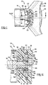
- a motor vehicle steering column 10 in a first embodiment, not forming part of the invention, includes a tubular mast jacket 12, a steering shaft 14 supported on the mast jacket for rotation about a longitudinal centerline thereof coincident with a centerline 16 of the steering shaft, and a steering wheel 18.
- the steering wheel 18 has a center hub 20, a plurality of structural metal spokes 22 welded to the hub, and a molded foam cushion 24 around the hub and the spokes.
- the foam cushion 24 is recessed over the hub 20 for installation of supplemental inflation restraint apparatus, not shown, behind a cover 26 over the center of the steering wheel.
- the hub 20 includes a planar front side 28, a planar back side 30, and an integral tubular boss 32 perpendicular to the back side 30.
- the structural spokes 22 are welded to the hub 20 at respective ones of a pair of opposite edges 34 thereof, Figures 2 and 5.
- a cylindrical passage 36 in the tubular boss 32 has a longitudinal centerline 37 and a pair of internal flat sides 38A-B converging in a V-shape.
- An eccentric cavity 39 in the front side 28 of the hub communicates with the passage 36 through a bottom 40 of the cavity, Figures 2 and 5.
- the cavity 39 has a cylindrical side wall 44 and a longitudinal centerline 46 parallel to the centerline 37 and laterally offset from the centerline 37 by an eccentric dimension "D", Figures 2, 3 and 5.
- the steering shaft 14 has a first cylindrical journal 50 and a smaller diameter, second cylindrical journal 54 adjacent thereto and separated therefrom by an annular shoulder 56.
- the diameter of the first cylindrical journal 50 is slightly smaller than the diameter of the passage 36 in the tubular boss 32 and is interrupted by a pair of flat sides 58A-B converging in the same V-shape as the flat sides 38A-B of the passage 36.
- the steering shaft extends into the tubular boss 32 until a shoulder 60 on the steering shaft engages the end of the boss.
- the centerline 16 of the steering shaft coincides with the centerline 37 of the passage 36 and the second cylindrical journal 54 is disposed in and coextensive with the eccentric cavity 39. Because of the eccentric dimension "D" between the centerlines 37 and 46, an annulus 62 separating the second cylindrical journal 54 on the steering shaft from the side wall 44 of the cavity 39 is correspondingly eccentric.
- An eccentric sleeve 64 has a cylindrical outer wall 66 and a cylindrical inner wall 68 eccentric relative to the outer wall by the dimension "D".
- the diameter of the outer wall 66 generally equals the diameter of the side wall 44 of the cavity 39 in the hub and the diameter of the inner wall 68 generally equals the diameter of the second cylindrical journal 54 on the steering shaft.
- the sleeve 64 has a seated position in the cavity 39 around the second cylindrical journal 54, Figure 3, when the eccentricities of the sleeve and the annulus 62 match, i.e., when the centerlines of the inner and outer walls 68,66 of the sleeve coincide with the centerlines 37,46 of the passage 36 and the cavity 39, respectively.
- the sleeve 64 has a perforation 70 and a notch 74 therein.
- the perforation 70 affords access to a first abutment 75 on the eccentric sleeve.
- the notch 74 affords access to a second abutment 76 on the eccentric sleeve parallel to the first abutment 75.
- the second cylindrical journal 54 on the steering shaft has a lateral groove 78 therein which registers with the perforation 70 in the eccentric sleeve 64 in the seated position of the sleeve in the cavity 39.
- the hub 20 has a lateral bore 80 therein which intersects the eccentric cavity 39 and which has an internal screw thread 82 in the portion thereof facing the first abutment 75.
- a control rod 84 is disposed in the lateral bore 82 and extends into the perforation 70 in the eccentric sleeve 64 and into the lateral groove 78 in the steering shaft with an inboard end 86 of the control rod juxtaposed the first abutment 75.
- An external screw thread 88 on the control rod engages the internal screw thread 82 in the lateral bore 80 so that rotation of the control rod advances and retracts the inboard end 86 of the control rod relative to the first abutment.
- the cushion 24 of the steering wheel is recessed on opposite sides of the lateral bore 80 to permit access to a socket 90 in the control rod and to the second abutment 76.
- the sleeve 64 With the hub 20 mounted on the steering shaft 14 as described and with the sleeve 64 in its seated position between the second journal 54 and the cavity 39, the sleeve 64 is rotated about the eccentric centerline 46 by inserting a tool in the socket 90 and rotating the control rod 84 to advance the inboard end 86 thereof against the abutment 75.
- the eccentric sleeve thrusts the hub and the steering shaft in opposite directions perpendicular to the centerline 16 of the steering shaft, i.e., laterally, causing the flat sides 58A-B on the shaft to wedge between the sides 38A-B of the passage 36.
- a rigid, lash-free driving connection is thus established between the steering shaft and the hub for unitary rotation of the two about the centerline 16 of the steering shaft.
- control rod is rotated in the opposite direction to withdraw the inboard end 86 from the first abutment 75 and a drift is inserted in the lateral bore 80 and forced against the second abutment 76 to unwedge the eccentric sleeve.
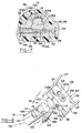
- a second embodiment 92 of a motor vehicle steering column includes a hub 94 having a planar front side 96, a planar back side 98, and an integral tubular boss 100 perpendicular to the back side 98.
- the structural spokes 22' are welded to the hub 94 at respective ones of a pair of opposite edges 34' thereof, Figures 6 and 8.
- a cylindrical passage 102 in the hub 94 extends through the tubular boss 100 and intersects the front side 96 of the hub.
- the internal wall of the cylindrical passage 102 is interrupted by a pair of flat sides 104A-B converging in a V-shape, Figure 7.
- a lateral bore 106 in the hub intersects the passage 102 and is divided by the latter into a first segment 108 on one side of the passage 102 and a second, internal screw threaded segment 110 on the other side of the passage 102.
- the lateral bore 106 traverses the passage 102 across the wide side or top of the V-shape defined by the flat sides 104A-B, Figure 7.
- a steering shaft 112 of the second preferred embodiment 92 has a cylindrical journal 114 at an upper or distal end thereof the diameter of which is slightly smaller than the diameter of the passage 102 in the hub.
- the cylindrical journal 114 is interrupted by a pair of flat sides 116A-B converging in the same V-shape as the flat sides 104A-B of the passage 102 and has a transverse or lateral notch 118 therein across the wide side or top of the V-shape defined by the flat sides 116A-B.
- the lateral notch 118 defines a segment of a frustoconical surface of revolution centered about a lateral axis 120, Figure 8, of the steering shaft.
- a control rod 130 of the second preferred embodiment 92 includes a cylindrical pilot 132 having a diameter matching the diameter of the first segment 108 of the lateral bore 106 in the hub, an external screw threaded barrel 134, and a frustoconical body 136 between the pilot 132 and the barrel 134 matching the lateral frustoconical notch 118.
- the control rod 130 With the cylindrical journal 114 of the steering shaft in the passage 102 in the hub, the control rod 130 is inserted in the lateral bore 106 to engage the internal and external screw threads on the second segment 110 and the barrel 134. The control rod is then rotated to advance the frustoconical body 136 thereof laterally against the lateral frustoconical notch 118 in the steering shaft. The lateral notch 118 cooperates with the frustoconical body 136 to convert lateral movement of the control rod into lateral thrust between the hub 94 and the steering shaft 112 which wedges the flat sides 116A-B on the shaft between the flat sides 104A-B of the passage 102.
- a rigid, lash-free driving connection is thus established between the steering shaft and the hub for unitary rotation of the two.
- the body 136 of the control rod 130 which traverses the lateral notch 118 in the steering shaft blocks dislodgment of the hub from the steering shaft.
Landscapes
- Engineering & Computer Science (AREA)
- Chemical & Material Sciences (AREA)
- Combustion & Propulsion (AREA)
- Transportation (AREA)
- Mechanical Engineering (AREA)
- Steering Controls (AREA)
Claims (2)
- Colonne de direction de véhicule à moteur (92) comportant un arbre de direction (112), un volant (18) ayant un moyeu (94) au niveau de son centre, dans laquelle un passage cylindrique (102) situé dans ledit moyeu est interrompu par une première paire de côtés plats (104A, 104B), parallèles à l'axe central longitudinal (128) dudit passage cylindrique, convergeant en une forme en V à partir d'un côté large dudit passage cylindrique vers un côté étroit dudit passage cylindrique, un tourillon cylindrique (114) situé sur ledit arbre de direction (112) étant interrompu par une seconde paire de côtés plats (116A, 116B) parallèles à l'axe central longitudinal (126) dudit tourillon cylindrique (114) convergeant en une forme en V correspondant à la forme en V de ladite première paire de côtés plats (104A, 104B) dudit passage cylindrique à partir d'un côté large dudit tourillon cylindrique vers un côté étroit dudit tourillon cylindrique,des moyens (118, 130) situés sur l'arbre de direction et sur le moyeu, ayant pour fonction d'induire une poussée latérale entre ledit moyeu (94) et ledit arbre de direction (112) de sorte que ladite première paire de côtés plats (116, 116B) est coincée entre ladite seconde paire de côtés plats (104A, 104B), et d'empêcher de manière positive la séparation dudit tourillon cylindrique (114) dudit passage cylindrique (102), caractérisée en ce que lesdits moyens pour induire une poussée latérale entre ledit moyeu et ledit arbre de direction et pour empêcher de manière positive la séparation dudit tourillon cylindrique dudit passage cylindrique comportent : un alésage latéral (106) agencé dans ledit moyeu (94) recoupant ledit passage cylindrique (102) à travers ledit côté large de celui-ci et comportant un premier segment d'un premier côté dudit passage cylindrique et un second segment d'un second côté opposé dudit passage cylindrique, situé sur l'axe central dudit alésage latéral commun avec ledit premier segment, une tige de commande (130) située dans ledit alésage latéral pouvant tourner autour dudit axe central commun ayant un corps tronconique (136) et une première extrémité d'un premier côté dudit corps tronconique située dans ledit premier segment dudit alésage latéral et une seconde extrémité située de l'autre côté dudit corps tronconique tourillonnée dans ledit second segment dudit alésage latéral, un filetage intérieur (110) situé dans ledit premier segment dudit alésage latéral, un pas de vis extérieur (134) agencé sur ladite première extrémité de ladite tige de commande venant en prise avec ledit filetage intérieur et coopérant avec celui-ci pour réaliser une translation linéaire de ladite tige de commande dans ledit alésage latéral dans la direction dudit axe central commun en réponse à la mise en rotation de ladite tige de commande, et une encoche latérale (118) située dans ledit premier tourillon cylindrique (114) à travers ledit côté large de celui-ci, située en vis-à-vis dudit alésage latéral dudit moyeu, ladite encoche latérale ayant une surface formant un angle par rapport audit axe central commun sensiblement égal à l'angle de cône dudit corps tronconique (136) de ladite tige de commande (130) de sorte que ledit corps tronconique (136) et ladite surface de ladite encoche latérale (118) coopèrent pour convertir la translation linéaire de ladite tige de commande dans la direction dudit axe central commun en poussée latérale dudit moyeu par rapport audit arbre de direction.ledit tourillon cylindrique (114) étant reçu dans ledit passage cylindrique (102), ladite première paire de côtés plats (104A, 104B) étant en vis-à-vis de ladite second paire de côtés plats (116A, 116B), et
- Colonne de direction de véhicule à moteur selon la revendication 1, dans laquelle ladite surface de ladite encore latérale (118) est un segment d'un corps de révolution tronconique sensiblement complémentaire dudit corps tronconique (136) de ladite tige de commande (130).
Applications Claiming Priority (4)
| Application Number | Priority Date | Filing Date | Title |
|---|---|---|---|
| US340999 | 1989-04-20 | ||
| US34099994A | 1994-11-17 | 1994-11-17 | |
| US08/420,162 US5588337A (en) | 1994-11-17 | 1995-04-11 | Motor vehicle steering column |
| US420162 | 1999-10-18 |
Publications (3)
| Publication Number | Publication Date |
|---|---|
| EP0712773A2 EP0712773A2 (fr) | 1996-05-22 |
| EP0712773A3 EP0712773A3 (fr) | 1996-09-18 |
| EP0712773B1 true EP0712773B1 (fr) | 1999-12-01 |
Family
ID=26992333
Family Applications (1)
| Application Number | Title | Priority Date | Filing Date |
|---|---|---|---|
| EP95202588A Expired - Lifetime EP0712773B1 (fr) | 1994-11-17 | 1995-09-26 | Colonne de direction d'un véhicule à moteur |
Country Status (4)
| Country | Link |
|---|---|
| US (1) | US5588337A (fr) |
| EP (1) | EP0712773B1 (fr) |
| JP (1) | JP2610411B2 (fr) |
| DE (1) | DE69513622T2 (fr) |
Cited By (1)
| Publication number | Priority date | Publication date | Assignee | Title |
|---|---|---|---|---|
| DE102004017695A1 (de) * | 2004-04-10 | 2005-10-27 | Valeo Sicherheitssysteme Gmbh | Vorrichtung mit mindestens zwei Bauteilen und einem bolzenförmigen Verbindungselement |
Families Citing this family (28)
| Publication number | Priority date | Publication date | Assignee | Title |
|---|---|---|---|---|
| JPH09123919A (ja) * | 1995-08-31 | 1997-05-13 | Toyoda Gosei Co Ltd | ステアリングホイールの取付構造 |
| JP3633050B2 (ja) * | 1995-08-31 | 2005-03-30 | 豊田合成株式会社 | ステアリングホイールの取付構造 |
| US5692770A (en) * | 1995-09-15 | 1997-12-02 | Breed Automotive Technology, Inc. | Modular steering wheel and airbag combination |
| DE29516622U1 (de) * | 1995-10-20 | 1996-01-25 | Trw Occupant Restraint Systems Gmbh, 73551 Alfdorf | Befestigung eines Fahrzeuglenkrades an einer Lenkwelle |
| AU683813B2 (en) * | 1996-02-26 | 1997-11-20 | Toyoda Gosei Co. Ltd. | Steering wheel, mounting structure thereof and boss structure thereof |
| DE19616234C2 (de) * | 1996-04-15 | 1998-07-16 | Petri Ag | Vorrichtung für die Befestigung einer Nabe auf einer Welle, insbesondere einer Lenkradnabe auf einer Lenksäule |
| US5685559A (en) * | 1996-04-25 | 1997-11-11 | Trw Inc. | Steering wheel with air bag module |
| WO1997047509A1 (fr) * | 1996-06-14 | 1997-12-18 | Breed Automotive Technology, Inc. | Ensemble tete de colonne pour montage du volant de direction |
| ES2149051B1 (es) * | 1996-07-12 | 2001-05-01 | Dalphi Metal Espana Sa | Nuevo sistema de fijacion lateral de la columna de direccion al volante de un vehiculo automovil. |
| US6122992A (en) * | 1996-10-29 | 2000-09-26 | Trw Inc. | Steering wheel and air bag assembly attachment to a steering shaft |
| US6134986A (en) * | 1997-03-20 | 2000-10-24 | Breed Automotive Technology, Inc. | Steering wheel assembly with improved gear |
| US5855449A (en) * | 1997-06-09 | 1999-01-05 | General Motors Corporation | Coupling between steering shaft and steering wheel |
| DE29808420U1 (de) * | 1998-05-05 | 1998-07-30 | Petri Ag, 63743 Aschaffenburg | Vorrichtung zur Befestigung einer Nabe auf einer Welle, insbesondere einer Lenkradnabe auf einer Lenksäule |
| US6033145A (en) * | 1998-07-25 | 2000-03-07 | Breed Automotive Technology, Inc. | Steering wheel attachment apparatus |
| US6357320B1 (en) * | 1998-11-18 | 2002-03-19 | Breed Automotive Technology, Inc. | Secure attachment of steering wheel to steering shaft |
| KR100320624B1 (ko) * | 1999-03-11 | 2002-01-12 | 이을재 | 전동차용 atc 신호발생 방법 및 장치 |
| US6199448B1 (en) * | 1999-11-09 | 2001-03-13 | Trw Inc. | Steering attachment with tapered pin and fastener |
| KR100380245B1 (ko) * | 1999-11-23 | 2003-04-14 | 주식회사 만도 | 자동차의 조향휠 조립구조 |
| US6314833B1 (en) * | 2000-05-31 | 2001-11-13 | Trw Inc. | Apparatus for attaching a vehicle steering wheel to a vehicle steering shaft |
| EP1164070B1 (fr) * | 2000-06-14 | 2005-03-23 | TRW Automotive Safety Systems GmbH | Fixation pour volant de véhicule |
| KR100380394B1 (ko) * | 2000-12-13 | 2003-04-16 | 기아자동차주식회사 | 자동차의 스티어링 휠 장착구조 |
| US6540429B2 (en) | 2001-01-26 | 2003-04-01 | Visteon Global Technologies, Inc. | Threaded rod and gear locking mechanism |
| US7640824B2 (en) * | 2006-09-13 | 2010-01-05 | Gm Global Technology Operations, Inc. | Central lock device of an adjustable steering column assembly |
| US7635149B2 (en) | 2007-03-21 | 2009-12-22 | Gm Global Technology Operations, Inc. | Rocker-arm lock device of an adjustable steering column assembly |
| US7621197B2 (en) * | 2007-03-21 | 2009-11-24 | Gm Global Technology Operations, Inc. | Releasable push/pull lock device of an adjustable steering column assembly |
| US7730804B2 (en) * | 2007-03-21 | 2010-06-08 | Gm Global Technology Operations, Inc. | Central lock device of an adjustable steering column assembly |
| US9027437B2 (en) | 2012-05-29 | 2015-05-12 | GM Global Technology Operations LLC | Steering wheels, steering wheel and steering column assemblies, and methods for assembling steering wheels and steering columns |
| DE102021208151A1 (de) | 2021-07-28 | 2023-02-02 | Thyssenkrupp Ag | Lenksäule für ein Steer-by-wire-Lenksystem eines Kraftfahrzeugs |
Citations (2)
| Publication number | Priority date | Publication date | Assignee | Title |
|---|---|---|---|---|
| US4372703A (en) * | 1981-01-12 | 1983-02-08 | The Singer Company | Tapered screw fastening means for bushings, sleeves and bearings |
| US5152627A (en) * | 1990-03-16 | 1992-10-06 | Reiche & Co. | Telescopable steering column of power vehicle |
Family Cites Families (21)
| Publication number | Priority date | Publication date | Assignee | Title |
|---|---|---|---|---|
| US50477A (en) * | 1865-10-17 | Improvement in journal-boxes | ||
| US1438004A (en) * | 1919-11-28 | 1922-12-05 | Edward H Vincent | Locking and tilting steering wheel |
| US1499432A (en) * | 1921-06-02 | 1924-07-01 | Manning Maxwell & Moore Inc | Rod-securing means |
| GB191223A (en) * | 1921-11-08 | 1923-01-11 | Armand Lorand | Improvements in keying devices for securing wheels, coupling sleeves, arms, brackets, and other articles upon shafts or shafting, or rods, spindles or the like |
| US1640763A (en) * | 1923-05-22 | 1927-08-30 | Inland Mfg Co | Locking steering wheel |
| US1600456A (en) * | 1925-06-30 | 1926-09-21 | Carl W Diekmann | Steering wheel |
| US1879936A (en) * | 1930-10-17 | 1932-09-27 | Mathew G Ivandick | Steering wheel mounting |
| US1862859A (en) * | 1931-02-03 | 1932-06-14 | Dallett Company | Locking device for pneumatic tools |
| DE1015704B (de) * | 1956-03-08 | 1957-09-12 | Petri Lenkradwerk | Abnehmbares Lenkrad fuer Kraftfahrzeuge |
| DE1094610B (de) * | 1956-03-08 | 1960-12-08 | Petri Lenkradwerk | Abnehmbares Lenkrad fuer Kraftfahrzeuge |
| US3434369A (en) * | 1965-08-05 | 1969-03-25 | Bendix Corp | No-lash axially movable steering column |
| US3572197A (en) * | 1968-12-10 | 1971-03-23 | Devlieg Machine Co | Adjustable toolholder |
| JPS5141264Y2 (fr) * | 1972-04-17 | 1976-10-07 | ||
| US4508467A (en) * | 1983-03-17 | 1985-04-02 | Choffin Justin C | Telescopically extendable pole |
| US4721008A (en) * | 1986-03-03 | 1988-01-26 | American Motors Corporation | Adjustable steering wheel hub |
| US4884469A (en) * | 1989-04-28 | 1989-12-05 | Detroit Marine Engineering Corporation | Steering wheel |
| US5144861A (en) * | 1990-03-19 | 1992-09-08 | Nihon Plast Co., Ltd. | Steering wheel construction |
| US5277323A (en) * | 1990-09-26 | 1994-01-11 | Westinghouse Air Brake Company | Locking wedge assembly to removably secure a male connection member in an articulated-type coupling arrangement |
| DE4106096C1 (fr) * | 1991-02-27 | 1992-10-15 | Jean Walterscheid Gmbh, 5204 Lohmar, De | |
| US5417518A (en) * | 1993-04-14 | 1995-05-23 | Bierwith; Robert | Tooth mounting adaptor for excavation bucket |
| US5267480A (en) * | 1992-07-10 | 1993-12-07 | Douglas Autotech Corporation | Telescoping column |
-
1995
- 1995-04-11 US US08/420,162 patent/US5588337A/en not_active Expired - Fee Related
- 1995-09-26 EP EP95202588A patent/EP0712773B1/fr not_active Expired - Lifetime
- 1995-09-26 DE DE69513622T patent/DE69513622T2/de not_active Expired - Fee Related
- 1995-11-17 JP JP7299676A patent/JP2610411B2/ja not_active Expired - Fee Related
Patent Citations (2)
| Publication number | Priority date | Publication date | Assignee | Title |
|---|---|---|---|---|
| US4372703A (en) * | 1981-01-12 | 1983-02-08 | The Singer Company | Tapered screw fastening means for bushings, sleeves and bearings |
| US5152627A (en) * | 1990-03-16 | 1992-10-06 | Reiche & Co. | Telescopable steering column of power vehicle |
Cited By (1)
| Publication number | Priority date | Publication date | Assignee | Title |
|---|---|---|---|---|
| DE102004017695A1 (de) * | 2004-04-10 | 2005-10-27 | Valeo Sicherheitssysteme Gmbh | Vorrichtung mit mindestens zwei Bauteilen und einem bolzenförmigen Verbindungselement |
Also Published As
| Publication number | Publication date |
|---|---|
| EP0712773A2 (fr) | 1996-05-22 |
| JP2610411B2 (ja) | 1997-05-14 |
| DE69513622T2 (de) | 2000-03-16 |
| US5588337A (en) | 1996-12-31 |
| DE69513622D1 (de) | 2000-01-05 |
| EP0712773A3 (fr) | 1996-09-18 |
| JPH08207781A (ja) | 1996-08-13 |
Similar Documents
| Publication | Publication Date | Title |
|---|---|---|
| US5588337A (en) | Motor vehicle steering column | |
| DE69506755T2 (de) | Vorrichtung zum Messen der Rotationsgeschwindigkeit eines Wälzlagers | |
| JP4149134B2 (ja) | ホイールサスペンションアセンブリ | |
| EP0756991B1 (fr) | Dispositif de pédalier pour bicyclette et dispositif d'assemblage | |
| US4938094A (en) | Device for effecting the fine adjustment of the angular orientation of a steering-wheel on a motor vehicle steering-wheel shaft | |
| US7547028B1 (en) | Tie rod steering linkage | |
| CA1275893C (fr) | Dispositif pour regler la position angulaire du volant d'une colonne de direction | |
| EP3225879B1 (fr) | Dispositif de came et dispositif de réglage de position pour volant de direction | |
| CA1141263A (fr) | Soupape de servo-direction et methode de fabrication | |
| KR100541143B1 (ko) | 핸들 부착 장치 | |
| GB2113629A (en) | Mounting for an adjustable steering column | |
| EP0475183A1 (fr) | Embrayage entre le moyeu du volant d'un véhicule automobile et la colonne de direction | |
| US5538273A (en) | Caser adjustment apparatus | |
| DE19931174A1 (de) | Radnaben- und Bremsrotoranordnung | |
| US4693136A (en) | Telescopic sub-assembly for a steering column | |
| US4509772A (en) | One-piece adjusting sleeve | |
| US4600205A (en) | Steering apparatus for motor vehicles | |
| EP0227276A1 (fr) | Bride non tournante pour la timonerie de direction d'une automobile | |
| US5605073A (en) | Motor vehicle steering column | |
| JPH0725310B2 (ja) | ステアリングコラム | |
| JP2002087285A (ja) | 車両用ステアリング装置 | |
| US4900076A (en) | Impact absorbing construction for a vehicle | |
| JP2007203771A (ja) | 車両用ステアリングコラム装置 | |
| KR100262425B1 (ko) | 파워스티어링 장치 | |
| US5975561A (en) | Steering shaft attachment |
Legal Events
| Date | Code | Title | Description |
|---|---|---|---|
| PUAI | Public reference made under article 153(3) epc to a published international application that has entered the european phase |
Free format text: ORIGINAL CODE: 0009012 |
|
| AK | Designated contracting states |
Kind code of ref document: A2 Designated state(s): DE FR GB |
|
| PUAL | Search report despatched |
Free format text: ORIGINAL CODE: 0009013 |
|
| AK | Designated contracting states |
Kind code of ref document: A3 Designated state(s): DE FR GB |
|
| 17P | Request for examination filed |
Effective date: 19970318 |
|
| 17Q | First examination report despatched |
Effective date: 19980709 |
|
| GRAG | Despatch of communication of intention to grant |
Free format text: ORIGINAL CODE: EPIDOS AGRA |
|
| GRAG | Despatch of communication of intention to grant |
Free format text: ORIGINAL CODE: EPIDOS AGRA |
|
| GRAH | Despatch of communication of intention to grant a patent |
Free format text: ORIGINAL CODE: EPIDOS IGRA |
|
| GRAH | Despatch of communication of intention to grant a patent |
Free format text: ORIGINAL CODE: EPIDOS IGRA |
|
| GRAA | (expected) grant |
Free format text: ORIGINAL CODE: 0009210 |
|
| AK | Designated contracting states |
Kind code of ref document: B1 Designated state(s): DE FR GB |
|
| REF | Corresponds to: |
Ref document number: 69513622 Country of ref document: DE Date of ref document: 20000105 |
|
| ET | Fr: translation filed | ||
| PLBE | No opposition filed within time limit |
Free format text: ORIGINAL CODE: 0009261 |
|
| STAA | Information on the status of an ep patent application or granted ep patent |
Free format text: STATUS: NO OPPOSITION FILED WITHIN TIME LIMIT |
|
| 26N | No opposition filed | ||
| REG | Reference to a national code |
Ref country code: GB Ref legal event code: IF02 |
|
| PGFP | Annual fee paid to national office [announced via postgrant information from national office to epo] |
Ref country code: GB Payment date: 20030911 Year of fee payment: 9 |
|
| PGFP | Annual fee paid to national office [announced via postgrant information from national office to epo] |
Ref country code: FR Payment date: 20030916 Year of fee payment: 9 |
|
| PGFP | Annual fee paid to national office [announced via postgrant information from national office to epo] |
Ref country code: DE Payment date: 20031024 Year of fee payment: 9 |
|
| PG25 | Lapsed in a contracting state [announced via postgrant information from national office to epo] |
Ref country code: GB Free format text: LAPSE BECAUSE OF NON-PAYMENT OF DUE FEES Effective date: 20040926 |
|
| REG | Reference to a national code |
Ref country code: GB Ref legal event code: 732E |
|
| PG25 | Lapsed in a contracting state [announced via postgrant information from national office to epo] |
Ref country code: DE Free format text: LAPSE BECAUSE OF NON-PAYMENT OF DUE FEES Effective date: 20050401 |
|
| GBPC | Gb: european patent ceased through non-payment of renewal fee |
Effective date: 20040926 |
|
| PG25 | Lapsed in a contracting state [announced via postgrant information from national office to epo] |
Ref country code: FR Free format text: LAPSE BECAUSE OF NON-PAYMENT OF DUE FEES Effective date: 20050531 |
|
| REG | Reference to a national code |
Ref country code: FR Ref legal event code: ST |