EP0714037A2 - Dispositif pour mesurer le spectre de transmission d'impulsions de quanta de rayons dispersés élastiquement - Google Patents
Dispositif pour mesurer le spectre de transmission d'impulsions de quanta de rayons dispersés élastiquement Download PDFInfo
- Publication number
- EP0714037A2 EP0714037A2 EP95203139A EP95203139A EP0714037A2 EP 0714037 A2 EP0714037 A2 EP 0714037A2 EP 95203139 A EP95203139 A EP 95203139A EP 95203139 A EP95203139 A EP 95203139A EP 0714037 A2 EP0714037 A2 EP 0714037A2
- Authority
- EP
- European Patent Office
- Prior art keywords
- primary
- detector
- plane
- ray
- arrangement
- Prior art date
- Legal status (The legal status is an assumption and is not a legal conclusion. Google has not performed a legal analysis and makes no representation as to the accuracy of the status listed.)
- Granted
Links
- 238000005259 measurement Methods 0.000 title description 4
- 238000001228 spectrum Methods 0.000 title 1
- 230000005855 radiation Effects 0.000 claims description 30
- 238000000411 transmission spectrum Methods 0.000 claims description 5
- 238000005192 partition Methods 0.000 claims description 4
- 230000000873 masking effect Effects 0.000 claims description 2
- 238000012216 screening Methods 0.000 abstract 3
- 239000011358 absorbing material Substances 0.000 description 3
- 238000004519 manufacturing process Methods 0.000 description 2
- 239000000126 substance Substances 0.000 description 2
- 238000010521 absorption reaction Methods 0.000 description 1
- 230000000694 effects Effects 0.000 description 1
- 239000002360 explosive Substances 0.000 description 1
- 238000003384 imaging method Methods 0.000 description 1
- 230000036540 impulse transmission Effects 0.000 description 1
Images


Classifications
-
- G—PHYSICS
- G01—MEASURING; TESTING
- G01V—GEOPHYSICS; GRAVITATIONAL MEASUREMENTS; DETECTING MASSES OR OBJECTS; TAGS
- G01V5/00—Prospecting or detecting by the use of ionising radiation, e.g. of natural or induced radioactivity
- G01V5/20—Detecting prohibited goods, e.g. weapons, explosives, hazardous substances, contraband or smuggled objects
- G01V5/22—Active interrogation, i.e. by irradiating objects or goods using external radiation sources, e.g. using gamma rays or cosmic rays
- G01V5/222—Active interrogation, i.e. by irradiating objects or goods using external radiation sources, e.g. using gamma rays or cosmic rays measuring scattered radiation
-
- G—PHYSICS
- G01—MEASURING; TESTING
- G01T—MEASUREMENT OF NUCLEAR OR X-RADIATION
- G01T1/00—Measuring X-radiation, gamma radiation, corpuscular radiation, or cosmic radiation
- G01T1/29—Measurement performed on radiation beams, e.g. position or section of the beam; Measurement of spatial distribution of radiation
Definitions
- Such an arrangement can, for example, identify certain substances in a piece of luggage, such as, in particular, crystalline substances (explosives) on the basis of their impulse transmission spectrum.
- the polychromatic X-rays generated by a single X-ray emitter are bundled with the aid of a slit opening in a primary diaphragm plate to form a conical primary beam.
- the radiation scattered in the examination area is through imaging slits of a secondary aperture arrangement, which can consist of one or more aperture plates, is imaged on a detector consisting of several elements.
- the diameter of the primary beam results approximately in the middle of the examination area (i.e. at a distance of 250 mm from the primary diaphragm plate) to about 90 mm. Since the objects to be examined generally have significantly larger dimensions, a meandering scanning movement is required in which all areas of the object are examined in succession.
- the invention has for its object to provide an arrangement of the type mentioned in such a way that the examination of an object is possible with less time.
- a second X-ray emitter is provided, which is arranged at substantially the same distance from the detector plane as the first X-ray emitter such that a second beam axis connecting the second X-ray emitter and the center of the detector underneath the first beam axis Intersects an angle and forms a beam axis pair with it, that both beam axes are assigned primary and secondary slot openings and that all primary and secondary slot openings extending around the first beam axis are open in the opposite direction to the plane defined by the beam axis pair as those around the second beam axis extending primary and secondary slot openings, the two ends of each semi-annular slot opening approximately in that of the Beam axis pair defined plane lie.
- the diameters of the primary slit openings are selected such that the first primary beam bundle, which is masked out by primary slit openings which extend around the first beam axis, borders in the examination area on the second primary beam bundle, which is blocked out by primary slit openings which extend around the second beam axis.
- the primary and / or the secondary slot openings are each in a single flat diaphragm plate, which is a particularly simple manufacture of the Aperture arrangements allowed.
- the diaphragm plates consist of X-ray absorbing material and / or are so thick that X-rays can only fall through the slit openings.
- the secondary slit openings are arranged in such a way that the scattered radiation of the first primary beam which is essentially scattered in a plane of the examination area lying parallel to the detector plane reaches the same annular element of a detector as the scattered radiation scattered in the same plane in the examination area of the second primary beam. This ensures that the scattered radiation striking a certain annular element of a detector is scattered under a relatively precisely defined scattering angle in the examination area.
- a development of the invention provides that between the examination area and the detector two collimator arrangements, each associated with a beam axis, with lamellae absorbing the X-radiation are provided and that the lamellae lie in planes which contain a beam axis.
- the lamellae of the two collimator arrangements are separated by a metallic partition wall that runs in one plane, in which are the two beam axes.
- the metallic The partition wall like the lamellae of the collimator arrangement, is made of X-ray absorbing material.
- a further development of the invention provides that at least one further detector is provided and that the primary diaphragm arrangement has two slot openings per detector. The greater the number of detectors, the greater the number of semi-conical primary beams passing through the examination area next to one another, and thus the area irradiated simultaneously being widened.
- all primary and secondary slit openings and all detectors are arranged in such a way that all the beam axes connecting the two X-ray emitters to the centers of the detectors lie in a single plane. This configuration is advantageous in view of the fact that the area simultaneously penetrated by several primary beams is as wide as possible.
- a particularly advantageous embodiment of the invention additionally provides that four detectors are provided and that the primary diaphragm arrangement has eight semi-ring-shaped slot openings. An area approximately 720 mm wide can then be examined simultaneously. Since items of luggage with a maximum width of 700 mm are generally to be examined, the meandering two-dimensional scanning movement can be dispensed with in this embodiment. A one-dimensional scanning movement is sufficient for the complete examination of such a piece of luggage, which on the one hand enables a simpler device for moving the piece of luggage with respect to the examination device and on the other hand a considerable one Saves time.
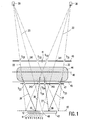
- 20 and 30 denote two identical X-ray emitters for generating polychromatic X-rays.
- the X-ray radiation falls on a flat primary diaphragm plate 40 which, as shown in FIG. 2 described below, has two essentially semi-ring-shaped slit openings 21 and 31, so that behind the primary diaphragm plate 40 two primary beams 22 and 32 are hidden.
- Fig. 1 of the primary slot openings 21 and 31 only those in Fig. 2 with S21 and S22 or S31 and S32 designated positions.
- the examination area in which the object 44 to be examined, for example a suitcase, is located, is defined by the primary diaphragm plate 40 and a parallel plate 45, for example of a conveyor belt, which is transparent to X-radiation and which is further away from the X-ray emitters 20 and 30 than the primary diaphragm plate 40 and has a distance of 500 mm from it, for example.
- the primary beams 22 and 32 adjoin one another.
- the two primary beams 22 and 32 each have the shape of the lateral surface of a half truncated cone, one of the half truncated cones protruding from the plane of the drawing and the other half of the truncated cone protruding into the plane of the drawing.
- a flat secondary diaphragm plate 47 which, as shown in FIG. 3 described further below, has secondary slot openings 25 and 35 which are essentially semi-ring-shaped.
- Fig. 1 of the secondary slot openings 25 and 35 only those in Fig. 3 with S23 and S24 or S33 and S34 designated positions.
- the detector device consists of a single detector 43 lying in a detector plane 42 parallel to the primary diaphragm plate 40 and the secondary diaphragm plate 47.
- the center 48 is the Intersection of two beam axes 23 and 33, which each pass through one of the X-ray emitters 20 and 30 and form a pair of beam axes.
- the beam axes 23 and 33 intersect the primary diaphragm plate 40 in points 241 and 341 and the secondary diaphragm plate in points 242 and 342.
- the slots S21 and S22 are arranged at the same distance from the intersection 241, and the slots S31 and S32 have the same distance from intersection 341.
- the same statement applies to the slots S23 and S24 or S33 and S34 with respect to the intersection points 242 and 342.
- the beam axes 23 and 33 therefore run in the center of the semi-conical primary beam 22 and 32 respectively.
- the primary beam 22 Since the beam axes 23 and 33 intersect in the detector plane 42 at point 48, only one detector 43 is required to detect the scattered radiation from both primary beams 22 and 32.
- the primary beam 22 generates scattered rays 26 and 27, which fall through the slots S23 and S24 onto the same annular detector element 5 as the scattered rays 36 and 37 generated by the primary beam 32, which fall through the slots S33 and S34 onto the detector element 5.
- the scattered radiation which is generated in the examination area essentially in a plane parallel to the detector plane 42 - for example in a region around the plane 46 - falls in the detector plane 42 on a specific annular detector element, regardless of which of the primary beams 22 and 32 is the Scattered radiation was generated.
- the x-ray emitters 20 and 30 are arranged at a distance of 2500 mm from the detector plane 42, it not being necessary for the two x-ray emitters to be exactly the same distance apart.
- the distance between the X-ray emitters 20 and 30 from the primary diaphragm plate 40 is 1187 mm, the distance between the primary aperture plate 40 and plate 45 is 500 mm.
- the X-ray emitters 20 and 30 are arranged at a distance of approximately 180 mm from one another.
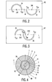
- the primary diaphragm plate 40 is shown in a plan view.
- the straight line E indicates the drawing plane from FIG. 1, which is perpendicular to the primary diaphragm plate 40 and at the same time is the plane which is defined by the beam axis pair formed from the beam axes 23 and 33.
- the intersections of the beam axes 23 and 33 with the primary diaphragm plate 40 are designated 241 and 341, respectively.
- the slot openings 21 and 31 are arranged such that they are open in the opposite direction to the plane indicated by E and are point symmetrical to point 41.
- the point 41 results in the primary diaphragm plate 40 as a point of intersection of a straight line which is perpendicular to the detector plane 42 in the center of the detector 48 (see FIG. 1) and intersects the connecting line of the two X-ray emitters 20 and 30 in the middle.
- FIG. 3 shows the secondary aperture plate 47 in a plan view.
- the half-ring-shaped secondary slot openings 25 and 35 also open in the opposite direction to the plane indicated by E and run around the beam axes 23 and 33 (see FIG. 1), whose intersections with the secondary aperture plate 47 are designated 242 and 342, respectively the secondary slot opening 25 is opened in the same direction to the plane indicated by E as the primary slot opening 21 from Fig. 2. Also in the secondary slot openings 25 and 35, the ends S23 and S24 or S33 and S34 are in the E indicated level.
- the primary and secondary slot openings 21 and 31 do not have to have the exact shape of a half circular ring, but should be essentially semi-ring-shaped, including slot openings that are included have the shape of a half ellipse. Due to the small opening half-angle of the x-ray radiation of 0.0309 rad and the large distance of the x-ray emitters 20 and 30 from the primary diaphragm plate 40 of 1187 mm, in practice the primary and secondary slit openings 21 and 31 or 25 and 35 will be semicircular in order to simplify production , although theoretically a weak elliptical deformation would be required.
- the detector shown in FIG. 4 shows a top view of the structure of twelve annular elements 1... 12 concentrically surrounding the center 48.
- the different elements 1 ... 12 serve to separately detect the scattered radiation from different sections of the examination area, i.e. measure the number of X-ray quanta striking them with energy resolution.
- the sections of the examination area are layer planes running parallel to the detector plane 42 (see FIG. 1) and in each case an area around these layer planes.
- the detector element 5 which is divided into the semi-annular partial elements 5A and 5B with the contact points 5C and 5D, detects the scattered rays 26 and 27 or 36 and 37 (see FIG. 1) such that only the scattered rays 26 onto the semi-annular partial element 5A and 27, only the scattered rays 36 and 37 strike the sub-element 5B. More generally, this means that scattered radiation generated by the primary beam 22 (see FIG. 1) only falls on the detector sub-elements above the plane indicated by E of the detector shown in FIG. 4, while that from the beam 32 (see FIG. 1) ) generated scattered radiation only falls on the detector sub-elements lying below the plane indicated by E.
- the scattering angle which the scattered radiation detected by a specific detector element includes with the associated primary beam, must be defined as precisely as possible. Therefore, only scatter radiation from a specific detector element should be registered in which the scatter beam runs in the plane defined by the primary beam causing it and the beam axis of this primary beam, or at least around a sector-shaped area around this plane.
- two collimator arrangements are provided between the examination area and the detector. These are omitted in FIG. 1 for the sake of clarity and shown in a sectional view in FIG. 5.
- the collimator arrangements essentially consist of each a tube halves 28 and 38 of X-ray absorbing material halved along the tube center axis. These tube halves 28 and 38 are separated by a metallic, X-ray absorbing partition 49, which lies in the drawing plane of FIG. 1, and are about the collimator axis 243 and 343, through which the beam axis 23 and 33 (see FIG. 1) runs, arranged. On the inside of the tube halves 28 and 38, fins 29 and 39 are attached at a uniform distance from one another, which are aligned radially with respect to the collimator axis 243 and 343, respectively.
- the X-ray emitters 20 and 30 in FIG. 1 are arranged at a distance from one another which corresponds approximately to twice the diameter of a semi-conical primary beam in plane 46, which in the case shown is approximately 90 mm.
- the beam axes 22 and 32 are not perpendicular to the detector plane 42.
- the scattering angle is thereby reduced by a factor which corresponds approximately to the cosine of the angle between the beam axis and the perpendicular on the detector plane 42, compared to the scattering angle in the case of the DE-A 42 22 227 known arrangement in which the beam axis is perpendicular to the detector plane.
- FIG. 6 A particularly advantageous embodiment of the invention is shown in FIG. 6.
- Four detectors 431 to 434 are provided, and the primary diaphragm arrangement has eight semi-ring-shaped slot openings in a primary diaphragm plate 401.
- the detectors 431 to 434 are arranged in the detector plane 42 in such a way that their ring-shaped elements each concentrically surround an intersection of two beam axes each passing through an X-ray emitter 20 or 30. These intersections are chosen so that in plane 46 the eight semi-conical primary beams 221 to 224 and 321 to 324 are offset next to one another and directly adjoin one another.
- the primary diaphragm plate 401 shown in FIG. 7 has eight semi-ring-shaped slot openings, of which three slot openings 212 to 214 assigned to the X-ray emitter 20 (not shown) exactly adjoin three slot openings 312 to 314 assigned to the X-ray emitter 30, so that three circular slot openings result therefrom.
- the two semi-ring-shaped slot openings 211 and 311 arranged on the outside do not adjoin a second semi-ring-shaped slot opening assigned to the respective other X-ray emitter.
- Points 51 to 53 are intersection points of two beam axes running through one of the X-ray emitters 20 and 30 and at the same time centers of the three circular slot openings 212/312 to 214/314. Only one beam axis runs through points 50 and 54 through one of the X-ray emitters 20 or 30.
- the secondary diaphragm arrangements and the collimator arrangements which are as in FIGS FIGS. 3 and 5 are shown with the difference that here four such arrangements are arranged between the examination object 44 and the detector plane 42.
- Each pair of primary beams 221, 321 to 224, 324 are assigned at least two semi-annular secondary slot openings shown in FIG. 3 and two collimator arrangements shown in FIG. 5.
- the area that can be examined at the same time is widened, for example by a factor of eight compared to the arrangement known from DE-A 42 22 227.
- the width of 700 mm which is the upper limit for the width dimension of a piece of luggage to be examined, has thus been reached, and the meandering scanning movement for the temporally successive examination of all areas of the object can be achieved by a one-dimensional scanning movement, in which the examination object is only linear in must be moved in a direction opposite to the examination arrangement.
- This also reduces the effort for the movement device, for example a conveyor belt, and leads to a substantial saving of time by a factor of eight. While in the known arrangement the examination of a large piece of luggage takes up to about twenty seconds, this embodiment of the arrangement according to the invention clearly falls short of the target time of six seconds for the examination of an object.
- FIG. 8 shows a further design option for a primary diaphragm plate 402.
- the intersection points of two beam axes, which run through the X-ray emitter 20 are identified by 55 and 57 with the primary diaphragm plate 402, and 56 and 58 the intersection points of two beam axes running through the X-ray emitter 30, also not shown.
- the position of the x-ray emitters 20 and 30 perpendicularly at a distance above the primary diaphragm plate 402 is indicated by points 201 and 301, which result from the vertical projection of the position of the x-ray emitters 20 and 30 onto the primary diaphragm plate 402.
- the beam axes extending through the intersection points 55 and 56 and in each case one of the X-ray emitters lie in the plane indicated by E1.
- the beam axes running through the intersection points 57 and 58 and one of the X-ray emitters each lie in the plane indicated by E2.
- the scattered radiation of the primary beams blocked by the semi-ring-shaped slot openings 215 and 315 is directed to a first detector with the aid of a secondary diaphragm arrangement, not shown, the scattered radiation of the primary beams blocked by the slot openings 216 and 316 is directed to a second detector.
- the examination area irradiated simultaneously is not only widened in one direction, but also enlarged in the direction perpendicular thereto.
- the semi-annular slot openings can be arranged such that the angle between a straight line perpendicular to the primary diaphragm plate 402 through one of the X-ray emitters and a primary beam of the X-ray radiation emanating from this X-ray emitter is a maximum of 15 °.
- small bores can also be provided in the arrangement according to the invention at the intersection of the beam axes with the primary and secondary diaphragm arrangements in order to reduce the intensity of a so-called central beam of each semi-conical primary beam bundle that is in its course coincides with the course of the beam axis.
- a small area is provided as the measuring area within the innermost detector ring in each detector.
- the secondary diaphragm arrangement can also consist of several flat secondary diaphragm plates with essentially semi-ring-shaped slot openings.
Landscapes
- Physics & Mathematics (AREA)
- Life Sciences & Earth Sciences (AREA)
- General Physics & Mathematics (AREA)
- High Energy & Nuclear Physics (AREA)
- Health & Medical Sciences (AREA)
- Molecular Biology (AREA)
- Spectroscopy & Molecular Physics (AREA)
- General Life Sciences & Earth Sciences (AREA)
- Geophysics (AREA)
- Analysing Materials By The Use Of Radiation (AREA)
- Measurement Of Radiation (AREA)
- Apparatus For Radiation Diagnosis (AREA)
Applications Claiming Priority (2)
| Application Number | Priority Date | Filing Date | Title |
|---|---|---|---|
| DE4441843 | 1994-11-24 | ||
| DE4441843A DE4441843A1 (de) | 1994-11-24 | 1994-11-24 | Anordnung zum Messen des Impulsübertragungsspektrums von elastisch gestreuten Röntgenquanten |
Publications (3)
| Publication Number | Publication Date |
|---|---|
| EP0714037A2 true EP0714037A2 (fr) | 1996-05-29 |
| EP0714037A3 EP0714037A3 (fr) | 1998-06-03 |
| EP0714037B1 EP0714037B1 (fr) | 2002-02-13 |
Family
ID=6534043
Family Applications (1)
| Application Number | Title | Priority Date | Filing Date |
|---|---|---|---|
| EP95203139A Expired - Lifetime EP0714037B1 (fr) | 1994-11-24 | 1995-11-16 | Dispositif pour mesurer le spectre de transmission d'impulsions de quanta de rayons dispersés élastiquement |
Country Status (4)
| Country | Link |
|---|---|
| US (1) | US5602893A (fr) |
| EP (1) | EP0714037B1 (fr) |
| JP (1) | JP3782142B2 (fr) |
| DE (2) | DE4441843A1 (fr) |
Cited By (2)
| Publication number | Priority date | Publication date | Assignee | Title |
|---|---|---|---|---|
| WO2008008665A3 (fr) * | 2006-07-11 | 2008-03-20 | Gen Electric | systèmes et procédés de développement d'un collimateur primaire |
| WO2010078981A1 (fr) * | 2009-01-12 | 2010-07-15 | Siemens Aktiengesellschaft | Procédé d'imagerie par rayons x utilisant un rayonnement diffus |
Families Citing this family (33)
| Publication number | Priority date | Publication date | Assignee | Title |
|---|---|---|---|---|
| DE4445876B4 (de) * | 1994-12-22 | 2005-08-04 | Philips Intellectual Property & Standards Gmbh | Anordnung zum Messen des Impulsübertragsspektrums von elastisch gestreuten Röntgenquanten |
| US5805663A (en) * | 1997-05-08 | 1998-09-08 | Futec, Inc. | Radiation imaging method and system |
| US6094472A (en) * | 1998-04-14 | 2000-07-25 | Rapiscan Security Products, Inc. | X-ray backscatter imaging system including moving body tracking assembly |
| EP1233264B1 (fr) * | 2001-01-17 | 2004-12-22 | YXLON International Security GmbH | Appareil pour la mesure du spectre de transfer de moment des photons rayons X |
| EP1241470B1 (fr) * | 2001-03-14 | 2003-09-24 | YXLON International X-Ray GmbH | Dispositif de mesure du transfert d'impulsion lors de la diffusion élastique de quantas de rayons x dans la région d' un conteneur à inspecter |
| DE102004035943B4 (de) * | 2004-07-23 | 2007-11-08 | GE Homeland Protection, Inc., , Newark | Röntgencomputertomograph sowie Verfahren zur Untersuchung eines Prüfteils mit einem Röntgencomputertomographen |
| CA2513990C (fr) * | 2004-08-27 | 2010-09-14 | Paul Jacob Arsenault | Reconstitution d'image a diffusion par rayons x, par equilibrage des ecarts entre les reponses de detecteurs, et dispositif connexe |
| GB0420222D0 (en) * | 2004-09-11 | 2004-10-13 | Koninkl Philips Electronics Nv | Coherent scatter imaging |
| DE102004060611B4 (de) * | 2004-12-16 | 2007-02-22 | Yxlon International Security Gmbh | Anordnung zum Messen des Impulsübertragungsspektrums von elastisch gestreuten Röntgenquanten |
| DE102005016656A1 (de) * | 2005-01-26 | 2006-08-10 | Smiths Heimann Gmbh | Kollimator mit einstellbarer Brennweite |
| WO2006135837A1 (fr) * | 2005-06-10 | 2006-12-21 | Xoran Technologies, Inc. | Tomodensitometre a sources multiples |
| EP2034898A2 (fr) * | 2006-06-22 | 2009-03-18 | Koninklijke Philips Electronics N.V. | Imagerie à rayons x à codage à sources multiples |
| US7773724B2 (en) * | 2006-07-11 | 2010-08-10 | Morpho Detection, Inc. | Systems and methods for generating an improved diffraction profile |
| US8995619B2 (en) | 2010-03-14 | 2015-03-31 | Rapiscan Systems, Inc. | Personnel screening system |
| US8576982B2 (en) | 2008-02-01 | 2013-11-05 | Rapiscan Systems, Inc. | Personnel screening system |
| US8638904B2 (en) | 2010-03-14 | 2014-01-28 | Rapiscan Systems, Inc. | Personnel screening system |
| US7796733B2 (en) * | 2007-02-01 | 2010-09-14 | Rapiscan Systems, Inc. | Personnel security screening system with enhanced privacy |
| GB0710579D0 (en) * | 2007-06-02 | 2007-07-11 | Univ Cranfield | Detecion of x-ray scattering |
| CN103064125B (zh) * | 2007-06-21 | 2016-01-20 | 瑞皮斯坎系统股份有限公司 | 用于提高受指引的人员筛查的系统和方法 |
| US8003949B2 (en) | 2007-11-01 | 2011-08-23 | Rapiscan Systems, Inc. | Multiple screen detection systems |
| CA2710655C (fr) | 2007-12-25 | 2018-06-12 | Rapiscan Systems, Inc. | Systeme de securite ameliore pour le criblage de personnes |
| CN101561405B (zh) * | 2008-04-17 | 2011-07-06 | 清华大学 | 一种直线轨迹扫描成像系统和方法 |
| WO2011063059A1 (fr) * | 2009-11-18 | 2011-05-26 | Rapiscan Systems, Inc. | Système et procédés à base de rayons x pour rechercher, dans les chaussures d'une personne, des menaces affectant la sécurité aéronautique |
| US20110188632A1 (en) * | 2010-02-03 | 2011-08-04 | Geoffrey Harding | Multiple plane multi-inverse fan-beam detection systems and method for using the same |
| GB2494963B (en) | 2010-03-14 | 2017-02-22 | Rapiscan Systems Inc | Multiple screen detection systems |
| US11280898B2 (en) | 2014-03-07 | 2022-03-22 | Rapiscan Systems, Inc. | Radar-based baggage and parcel inspection systems |
| KR20160130482A (ko) | 2014-03-07 | 2016-11-11 | 라피스캔 시스템스, 인코포레이티드 | 초광대역 검출기 |
| AU2015353439A1 (en) | 2014-11-25 | 2017-06-29 | Rapiscan Systems, Inc. | Intelligent security management system |
| EP3520120A4 (fr) | 2016-09-30 | 2020-07-08 | American Science & Engineering, Inc. | Source de rayons x pour imagerie à faisceau de balayage 2d |
| WO2018154308A1 (fr) * | 2017-02-25 | 2018-08-30 | The Nottingham Trent University | Appareil d'inspection d'échantillon utilisant un détecteur de diffraction |
| WO2019006310A1 (fr) * | 2017-06-29 | 2019-01-03 | Cuadros Angela | Système d'ouverture codée à bord k pixelisé pour imagerie par rayons x à spectre de compression |
| GB2577856B (en) * | 2018-07-24 | 2020-12-16 | The Nottingham Trent Univ | A sample inspection system |
| CN113253331B (zh) * | 2021-05-11 | 2022-03-01 | 中国工程物理研究院激光聚变研究中心 | 一种基于布拉格菲涅耳波带片的icf热斑三维编码成像方法 |
Citations (1)
| Publication number | Priority date | Publication date | Assignee | Title |
|---|---|---|---|---|
| DE4222227A1 (de) | 1992-07-07 | 1994-01-13 | Philips Patentverwaltung | Anordnung zum Messen des Impulsübertragsspektrums von elastisch gestreuten Röntgenquanten |
Family Cites Families (4)
| Publication number | Priority date | Publication date | Assignee | Title |
|---|---|---|---|---|
| DE3443095A1 (de) * | 1984-11-27 | 1986-05-28 | Philips Patentverwaltung Gmbh, 2000 Hamburg | Anordnung zur untersuchung eines koerpers mit gamma- oder roentgenstrahlung |
| DE4034602A1 (de) * | 1990-06-20 | 1992-05-07 | Philips Patentverwaltung | Anordnung zur messung des impulsuebertragsspektrums von roentgenquanten |
| DE59308726D1 (de) * | 1992-02-06 | 1998-08-13 | Philips Patentverwaltung | Anordnung zum Messen des Impulsübertragsspektrums von elastisch gestreuten Röntgenquanten |
| DE4203354A1 (de) * | 1992-02-06 | 1993-08-12 | Philips Patentverwaltung | Anordnung zum messen des impulsuebertragsspektrums von roentgenquanten |
-
1994
- 1994-11-24 DE DE4441843A patent/DE4441843A1/de not_active Withdrawn
-
1995
- 1995-11-16 EP EP95203139A patent/EP0714037B1/fr not_active Expired - Lifetime
- 1995-11-16 DE DE59510051T patent/DE59510051D1/de not_active Expired - Lifetime
- 1995-11-21 US US08/560,238 patent/US5602893A/en not_active Expired - Lifetime
- 1995-11-24 JP JP30599695A patent/JP3782142B2/ja not_active Expired - Lifetime
Patent Citations (1)
| Publication number | Priority date | Publication date | Assignee | Title |
|---|---|---|---|---|
| DE4222227A1 (de) | 1992-07-07 | 1994-01-13 | Philips Patentverwaltung | Anordnung zum Messen des Impulsübertragsspektrums von elastisch gestreuten Röntgenquanten |
Cited By (3)
| Publication number | Priority date | Publication date | Assignee | Title |
|---|---|---|---|---|
| WO2008008665A3 (fr) * | 2006-07-11 | 2008-03-20 | Gen Electric | systèmes et procédés de développement d'un collimateur primaire |
| US7881437B2 (en) | 2006-07-11 | 2011-02-01 | Morpho Detection, Inc. | Systems and methods for developing a primary collimator |
| WO2010078981A1 (fr) * | 2009-01-12 | 2010-07-15 | Siemens Aktiengesellschaft | Procédé d'imagerie par rayons x utilisant un rayonnement diffus |
Also Published As
| Publication number | Publication date |
|---|---|
| JPH08220245A (ja) | 1996-08-30 |
| JP3782142B2 (ja) | 2006-06-07 |
| US5602893A (en) | 1997-02-11 |
| EP0714037A3 (fr) | 1998-06-03 |
| EP0714037B1 (fr) | 2002-02-13 |
| DE59510051D1 (de) | 2002-03-21 |
| DE4441843A1 (de) | 1996-05-30 |
Similar Documents
| Publication | Publication Date | Title |
|---|---|---|
| EP0714037B1 (fr) | Dispositif pour mesurer le spectre de transmission d'impulsions de quanta de rayons dispersés élastiquement | |
| EP0312851B1 (fr) | Dispositif de balayage à rayons X | |
| DE69624685T2 (de) | Einrichtung zur roentgenstrahlenuntersuchung | |
| DE69619671T2 (de) | Mehrkanal-totalreflexionsoptik mit steuerbarer divergenz | |
| EP1241470B1 (fr) | Dispositif de mesure du transfert d'impulsion lors de la diffusion élastique de quantas de rayons x dans la région d' un conteneur à inspecter | |
| EP0462658A2 (fr) | Dispositif pour la mesure du spectre de transfert d'impulsions de quanta de rayonnement X | |
| DE3909147A1 (de) | Anordnung zur messung des impulsuebertrages | |
| DE3689231T2 (de) | Röntgenstrahlquelle. | |
| EP0556887B1 (fr) | Dispositif pour la mesure du spectre de transfert d'impulsions de quantor de rayonnement X | |
| EP0184247B1 (fr) | Agencement destiné à l'examen d'un corps à l'aide d'un rayonnement gamma ou de Röntgen | |
| EP0466956A1 (fr) | Appareil de tomographie | |
| DE69127957T2 (de) | Ionenstreuungsspektrometer | |
| DE2331091C3 (de) | Einrichtung zur Bestimmung der Energie geladener Teilchen | |
| DE2705430C3 (de) | Elektrostatischer Analysator für geladene Teilchen | |
| DE2458025A1 (de) | Vorrichtung fuer massenanalyse und strukturanalyse einer oberflaechenschicht durch ionenstreuung | |
| DE10125454B4 (de) | Gerät zur Röntgenanalyse mit einem Mehrschichtspiegel und einem Ausgangskollimator | |
| AT392160B (de) | Blendenanordnung zur streuungsarmen, einseitigen, linearen begrenzung eines roentgenstrahlbuendels | |
| EP3928085B1 (fr) | Dispositif de mesure de rayonnement x pour une mesure 1d continue | |
| DE3005352A1 (de) | Optische anordnung zum erzeugen von zeitlich aufeinanderfolgenden messstrahlenbuendeln unterschiedlicher wellenlaenge | |
| EP1233264B1 (fr) | Appareil pour la mesure du spectre de transfer de moment des photons rayons X | |
| DE2835978C3 (de) | Energieanalysator zur Analyse der Energie geladener Teilchen | |
| DE4222227A1 (de) | Anordnung zum Messen des Impulsübertragsspektrums von elastisch gestreuten Röntgenquanten | |
| DE2003753A1 (de) | Blendenanordnung zur Begrenzung eines Roentgenstrahlenbuendels | |
| DE4445876B4 (de) | Anordnung zum Messen des Impulsübertragsspektrums von elastisch gestreuten Röntgenquanten | |
| DE3915612A1 (de) | Vorrichtung zum nachweis ionisierender strahlen |
Legal Events
| Date | Code | Title | Description |
|---|---|---|---|
| PUAI | Public reference made under article 153(3) epc to a published international application that has entered the european phase |
Free format text: ORIGINAL CODE: 0009012 |
|
| AK | Designated contracting states |
Kind code of ref document: A2 Designated state(s): DE FR GB |
|
| PUAL | Search report despatched |
Free format text: ORIGINAL CODE: 0009013 |
|
| RHK1 | Main classification (correction) |
Ipc: G01T 1/29 |
|
| AK | Designated contracting states |
Kind code of ref document: A3 Designated state(s): DE FR GB |
|
| RAP3 | Party data changed (applicant data changed or rights of an application transferred) |
Owner name: KONINKLIJKE PHILIPS ELECTRONICS N.V. Owner name: PHILIPS PATENTVERWALTUNG GMBH |
|
| 17P | Request for examination filed |
Effective date: 19981203 |
|
| RAP3 | Party data changed (applicant data changed or rights of an application transferred) |
Owner name: KONINKLIJKE PHILIPS ELECTRONICS N.V. Owner name: PHILIPS CORPORATE INTELLECTUAL PROPERTY GMBH |
|
| 17Q | First examination report despatched |
Effective date: 20000915 |
|
| GRAG | Despatch of communication of intention to grant |
Free format text: ORIGINAL CODE: EPIDOS AGRA |
|
| GRAG | Despatch of communication of intention to grant |
Free format text: ORIGINAL CODE: EPIDOS AGRA |
|
| GRAH | Despatch of communication of intention to grant a patent |
Free format text: ORIGINAL CODE: EPIDOS IGRA |
|
| GRAH | Despatch of communication of intention to grant a patent |
Free format text: ORIGINAL CODE: EPIDOS IGRA |
|
| GRAA | (expected) grant |
Free format text: ORIGINAL CODE: 0009210 |
|
| REG | Reference to a national code |
Ref country code: GB Ref legal event code: IF02 |
|
| AK | Designated contracting states |
Kind code of ref document: B1 Designated state(s): DE FR GB |
|
| REF | Corresponds to: |
Ref document number: 59510051 Country of ref document: DE Date of ref document: 20020321 |
|
| GBT | Gb: translation of ep patent filed (gb section 77(6)(a)/1977) |
Effective date: 20020412 |
|
| ET | Fr: translation filed | ||
| RAP2 | Party data changed (patent owner data changed or rights of a patent transferred) |
Owner name: KONINKLIJKE PHILIPS ELECTRONICS N.V. Owner name: PHILIPS CORPORATE INTELLECTUAL PROPERTY GMBH |
|
| REG | Reference to a national code |
Ref country code: GB Ref legal event code: 746 Effective date: 20020917 |
|
| REG | Reference to a national code |
Ref country code: FR Ref legal event code: D6 |
|
| PLBE | No opposition filed within time limit |
Free format text: ORIGINAL CODE: 0009261 |
|
| STAA | Information on the status of an ep patent application or granted ep patent |
Free format text: STATUS: NO OPPOSITION FILED WITHIN TIME LIMIT |
|
| 26N | No opposition filed |
Effective date: 20021114 |
|
| ET | Fr: translation filed | ||
| REG | Reference to a national code |
Ref country code: DE Ref legal event code: R081 Ref document number: 59510051 Country of ref document: DE Owner name: KONINKLIJKE PHILIPS N.V., NL Free format text: FORMER OWNERS: PHILIPS INTELLECTUAL PROPERTY & STANDARDS GMBH, 20099 HAMBURG, DE; KONINKLIJKE PHILIPS ELECTRONICS N.V., EINDHOVEN, NL Effective date: 20140327 Ref country code: DE Ref legal event code: R081 Ref document number: 59510051 Country of ref document: DE Owner name: PHILIPS GMBH, DE Free format text: FORMER OWNERS: PHILIPS INTELLECTUAL PROPERTY & STANDARDS GMBH, 20099 HAMBURG, DE; KONINKLIJKE PHILIPS ELECTRONICS N.V., EINDHOVEN, NL Effective date: 20140327 Ref country code: DE Ref legal event code: R081 Ref document number: 59510051 Country of ref document: DE Owner name: PHILIPS GMBH, DE Free format text: FORMER OWNER: PHILIPS INTELLECTUAL PROPERTY &, KONINKLIJKE PHILIPS ELECTRONICS, , NL Effective date: 20140327 Ref country code: DE Ref legal event code: R081 Ref document number: 59510051 Country of ref document: DE Owner name: PHILIPS DEUTSCHLAND GMBH, DE Free format text: FORMER OWNER: PHILIPS INTELLECTUAL PROPERTY &, KONINKLIJKE PHILIPS ELECTRONICS, , NL Effective date: 20140327 Ref country code: DE Ref legal event code: R081 Ref document number: 59510051 Country of ref document: DE Owner name: KONINKLIJKE PHILIPS N.V., NL Free format text: FORMER OWNER: PHILIPS INTELLECTUAL PROPERTY &, KONINKLIJKE PHILIPS ELECTRONICS, , NL Effective date: 20140327 |
|
| REG | Reference to a national code |
Ref country code: FR Ref legal event code: CD Owner name: PHILIPS CORPORATE INTELLECTUAL PR Effective date: 20141126 Ref country code: FR Ref legal event code: CA Effective date: 20141126 |
|
| PGFP | Annual fee paid to national office [announced via postgrant information from national office to epo] |
Ref country code: GB Payment date: 20141128 Year of fee payment: 20 |
|
| PGFP | Annual fee paid to national office [announced via postgrant information from national office to epo] |
Ref country code: FR Payment date: 20141126 Year of fee payment: 20 |
|
| PGFP | Annual fee paid to national office [announced via postgrant information from national office to epo] |
Ref country code: DE Payment date: 20150129 Year of fee payment: 20 |
|
| REG | Reference to a national code |
Ref country code: DE Ref legal event code: R082 Ref document number: 59510051 Country of ref document: DE Representative=s name: MEISSNER, BOLTE & PARTNER GBR, DE Ref country code: DE Ref legal event code: R081 Ref document number: 59510051 Country of ref document: DE Owner name: PHILIPS GMBH, DE Free format text: FORMER OWNERS: KONINKLIJKE PHILIPS N.V., EINDHOVEN, NL; PHILIPS DEUTSCHLAND GMBH, 20099 HAMBURG, DE Ref country code: DE Ref legal event code: R081 Ref document number: 59510051 Country of ref document: DE Owner name: KONINKLIJKE PHILIPS N.V., NL Free format text: FORMER OWNERS: KONINKLIJKE PHILIPS N.V., EINDHOVEN, NL; PHILIPS DEUTSCHLAND GMBH, 20099 HAMBURG, DE |
|
| REG | Reference to a national code |
Ref country code: DE Ref legal event code: R071 Ref document number: 59510051 Country of ref document: DE |
|
| REG | Reference to a national code |
Ref country code: GB Ref legal event code: PE20 Expiry date: 20151115 |
|
| PG25 | Lapsed in a contracting state [announced via postgrant information from national office to epo] |
Ref country code: GB Free format text: LAPSE BECAUSE OF EXPIRATION OF PROTECTION Effective date: 20151115 |