EP3928085B1 - Dispositif de mesure de rayonnement x pour une mesure 1d continue - Google Patents
Dispositif de mesure de rayonnement x pour une mesure 1d continue Download PDFInfo
- Publication number
- EP3928085B1 EP3928085B1 EP20705958.5A EP20705958A EP3928085B1 EP 3928085 B1 EP3928085 B1 EP 3928085B1 EP 20705958 A EP20705958 A EP 20705958A EP 3928085 B1 EP3928085 B1 EP 3928085B1
- Authority
- EP
- European Patent Office
- Prior art keywords
- measurement
- detector modules
- detector
- modules
- ray
- Prior art date
- Legal status (The legal status is an assumption and is not a legal conclusion. Google has not performed a legal analysis and makes no representation as to the accuracy of the status listed.)
- Active
Links
Images


Classifications
-
- G—PHYSICS
- G01—MEASURING; TESTING
- G01N—INVESTIGATING OR ANALYSING MATERIALS BY DETERMINING THEIR CHEMICAL OR PHYSICAL PROPERTIES
- G01N23/00—Investigating or analysing materials by the use of wave or particle radiation, e.g. X-rays or neutrons, not covered by groups G01N3/00 – G01N17/00, G01N21/00 or G01N22/00
- G01N23/20—Investigating or analysing materials by the use of wave or particle radiation, e.g. X-rays or neutrons, not covered by groups G01N3/00 – G01N17/00, G01N21/00 or G01N22/00 by using diffraction of the radiation by the materials, e.g. for investigating crystal structure; by using scattering of the radiation by the materials, e.g. for investigating non-crystalline materials; by using reflection of the radiation by the materials
- G01N23/20008—Constructional details of analysers, e.g. characterised by X-ray source, detector or optical system; Accessories therefor; Preparing specimens therefor
-
- G—PHYSICS
- G01—MEASURING; TESTING
- G01N—INVESTIGATING OR ANALYSING MATERIALS BY DETERMINING THEIR CHEMICAL OR PHYSICAL PROPERTIES
- G01N23/00—Investigating or analysing materials by the use of wave or particle radiation, e.g. X-rays or neutrons, not covered by groups G01N3/00 – G01N17/00, G01N21/00 or G01N22/00
- G01N23/20—Investigating or analysing materials by the use of wave or particle radiation, e.g. X-rays or neutrons, not covered by groups G01N3/00 – G01N17/00, G01N21/00 or G01N22/00 by using diffraction of the radiation by the materials, e.g. for investigating crystal structure; by using scattering of the radiation by the materials, e.g. for investigating non-crystalline materials; by using reflection of the radiation by the materials
- G01N23/207—Diffractometry using detectors, e.g. using a probe in a central position and one or more displaceable detectors in circumferential positions
-
- G—PHYSICS
- G01—MEASURING; TESTING
- G01N—INVESTIGATING OR ANALYSING MATERIALS BY DETERMINING THEIR CHEMICAL OR PHYSICAL PROPERTIES
- G01N2223/00—Investigating materials by wave or particle radiation
- G01N2223/50—Detectors
- G01N2223/501—Detectors array
-
- G—PHYSICS
- G01—MEASURING; TESTING
- G01N—INVESTIGATING OR ANALYSING MATERIALS BY DETERMINING THEIR CHEMICAL OR PHYSICAL PROPERTIES
- G01N2223/00—Investigating materials by wave or particle radiation
- G01N2223/60—Specific applications or type of materials
- G01N2223/62—Specific applications or type of materials powders
Definitions
- X-rays can be used for the non-destructive investigation of the crystal structure of a sample to be measured.
- the X-rays are diffracted at the lattice planes of the crystals in the sample or the associated atoms.
- the spatial distribution of the diffracted X-rays can be used to draw conclusions about the crystal structure or properties of the sample to be examined.
- Zero-dimensional X-ray detectors allow the detection of X-rays in a very small solid angle range; therefore, during the measurement, the X-ray detector is typically scanned over a solid angle range of interest, for example with a goniometer.
- One-dimensional detectors allow spatially resolved detection of X-rays along one spatial direction ("measurement direction"). Two-dimensional detectors even allow spatially resolved detection along two spatial directions, but are comparatively expensive.
- X-ray diffraction measurement is the examination of powder samples with an X-ray beam, whereby so-called Debye rings appear in the diffraction pattern. These represent specific lattice spacings in the crystal. Due to the random orientation of the individual grains in a powder sample to the incident X-ray beam, each grain diffracts the X-ray beam through the corresponding lattice plane to a predetermined location of the associated Debye ring, and the Debye ring is essentially evenly illuminated by the entirety of the diffracting powder grains. Accordingly, the information about the powder sample already in a small part of the circumference of the Debye rings.
- a diffraction pattern of a powder sample (“powder diffractogram"), it is therefore sufficient to evaluate the diffraction pattern in a spatially resolved manner along any radial direction across the Debye rings.
- a one-dimensional X-ray detector can be used for this purpose.
- one-dimensional measurement information may be sufficient to obtain desired information about a sample.
- a detector module for a typical one-dimensional X-ray detector comprises an active zone and a dead zone surrounding the active zone. If an X-ray quantum hits the active zone, it is detected. If an X-ray quantum hits the dead zone, it is not detected. In practice, the dead zone is necessary to set up the structural elements for the active zone.
- the active zone of the detector module is usually longer along a measuring direction in which the active zone allows spatial resolution than across this direction.
- Typical detector modules for one-dimensional X-ray detectors can be designed as semiconductor detector modules in which the active zone is divided into (often strip-shaped) sensor elements with which a spatial resolution is achieved, see for example G. Lutz, "Semiconductor Radiation Detectors - Device Physics", Springer-Verlag Berlin, 2nd edition 2007, pages 109-111 and 229-233 .
- detector modules for one-dimensional X-ray detectors can be designed as gas detectors (also called gas-filled proportional detectors), in which an X-ray quantum triggers a charge pulse that runs to opposite edges of the active zone, so that the point of impact on the gas detector can be determined from the travel time difference, cf. for example GF Knoll, “Radiation Detection and Measurement”, John Wiley and Sons, Inc., New York, Second Edition 1989, page 190 , or even FHW Heuck, E. Macherauch, "Research with X-rays: A Century's Review (1895-1995)", Springer-Verlag Berlin 1995, pages 359-360 .
- An arc-shaped gas detector is also used in L.
- Suitable X-ray diffractometers are, for example, the ARL EQUINOX 100 Benchtop x-ray diffractometer from Thermo Fisher Scientific, see company brochure " Thermo Scientific ARL EQUINOX 100 X-ray diffractometers", 11/2018, or by the FCT-ACTech Continuous On Stream Mineral Analyser COSMA, see http://www.fct-actech.com/site/pages/equipment.php, downloaded on 8.2.2019 , known; these can be equipped with curved spatially resolving detectors, such as those offered by INEL Inc., Stratham NH, USA, see http://www.inel.us/index.php/accessories-xrd-inel-company/detector-curved-inel-company , downloaded on February 8, 2019.
- gas detectors are limited in the global count rate (usually around 1 Mcps), and have poorer spatial resolution and energy resolution compared to semiconductor-based detector modules, as well as limited durability.
- the measurement of the diffraction pattern along the circular arc has gaps in the area of the dead zones, which are the active zones of the detector modules surrounded by two gaps. Diffraction information from the gap area must be dispensed with, or the detector modules must be moved along the circular arc and the measurement then repeated in order to obtain complete diffraction information.
- PR Willmott et al., J. Synchrotron Rad. (2013) 20, pp. 667-682 describes an improved X-ray detector of the Mythen II type, wherein two groups of detector modules are arranged around a sample position.
- the first group of detector modules comprises detector modules arranged azimuthally one behind the other at a first radius
- the second group comprises detector modules arranged azimuthally one behind the other at a second radius, where the second radius is larger than the first radius.
- Detectors from the second group are arranged at azimuthal gaps in the first group of detectors and vice versa.
- the detector modules each have sensor elements arranged one after the other in the azimuthal direction.
- CirPAD arc detector from imXPAD in cooperation with Synchrotron SOLEIL, Gif-sur-Yvette, France, has made an X-ray detector known in which the detector modules are arranged along a circular arc, whereby the arrangement is intended to enable reduced module spacing, cf. https://www.synchrotron-soleil.fr/en/news/new-detector-diffabs-fast-measurements-x-ray-diffraction-imaqes , downloaded on February 7, 2019.
- the CirPAD detector is also mentioned in the presentation "Résolution de structures à Vietnamese de diagrammes de diffraction de Doorss", Erik Elkaim, isme de Cristallographie, October 17-21, 2016, slide 12 there.
- the PI-LATUS 1M Detector is also an X-ray detector in which a partial overlap of detector modules is set up by arranging the detector modules one behind the other (with linearly increasing offset) with respect to a local connection direction to the sample position. However, due to the absorption of X-ray quanta in the front sensor, areas remain without detection.
- X-ray detectors with semiconductor-based detector modules are the HyPix-Arc 150° from Rigaku, see https://www.rigaku.com/en/arc , downloaded on 8.2.2019, or the X-ray diffractometers from Stresstech, see e.g. company brochure " Xstress 3000 G3/G3R", Stresstech GmbH, Rennerod, DE, undated, downloaded 8.2.2019 , or the SmartSite RS portable stress analyzer from Rigaku, see https://www.rigaku.com/en/products/xrd/smartsite-rs, downloaded on February 8, 2019 , or by the US 2017/0097309 A1 became known.
- an X-ray detector for a computed tomography imaging system has become known in which detector modules are arranged one behind the other in overlapping areas in the direction of beam propagation.
- the measuring arrangement provides that at least some of the detector modules which follow one another in the measuring direction form overlapping regions in which at least two detector modules overlap in the measuring direction and are arranged next to one another in the transverse direction, wherein the active zones of the detector modules in the overlapping regions directly adjoin one another in the measuring direction or overlap in the measuring direction, so that the entirety of the active zones of the detector modules enables a gapless measurement of the X-rays emanating from the sample position in the measuring direction, and wherein the detector modules are arranged overlapping along a circular arc around the sample position, wherein the circular arc defines the local measuring direction at each detector module, and the detector modules are each formed on a flat substrate which is oriented perpendicular to the local connection direction to the sample position, and wherein the measuring direction, the transverse direction and the connection direction are approximately perpendicular to one another at the respective detector module.
- the measuring arrangement according to the invention is used for the simple and seamless determination of 1D measurement data or measurement information about a measurement sample.
- the detector modules or their active zones can each provide measurement data resolved in the measurement direction (intensity as a function of the position in the measurement direction).
- the overlapping areas set up can provide a seamless overall measurement data set (intensity as a function of the position in the measurement direction) across the detector modules that follow one another in the measurement direction.
- the unavoidable dead zones of the individual detector modules do not create any gaps in the overall data set.
- all detector modules of the X-ray detector according to the invention form overlapping areas with all of their next neighboring detector modules in the measurement direction.
- the overlapping areas according to the invention ensure that the dead zone of a detector module, as long as it is not overlapped by at least one active zone of this detector module itself in the measuring direction, is overlapped by an active zone of at least one further detector module in the measuring direction.
- This further detector module is arranged at least partially next to the detector module in the transverse direction, which is structurally simple and avoids mutual shading of the detector module and the further detector module or at least of their active zones with respect to the connection direction to the sample position.
- the detector module and the further detector module are accordingly typically arranged at identical positions in the connection direction and do not lie one above the other with respect to the connection direction, and in particular the detector module does not lie above an active zone of the further detector module with respect to the connection direction and vice versa.
- the detector modules are arranged overlapping along the circular arc, at the center of which the sample position is located, and the circular arc defines the local measurement direction on each detector module.
- Particularly precise diffraction measurements can be carried out with only minor measurement errors due to parallax effects.
- the measurement direction can be guided (approximately) perpendicular to the local connection direction to the sample; it should be noted that in practice the overall curved course of the measurement direction is locally approximated in sections by a straight course (straight substrates of the individual detector modules) and kinks (at substrate transitions).
- the detector modules are each arranged on a flat substrate that is perpendicular to the local connection direction to the sample position. This combines a simple, practical, cost-effective construction of the detector modules with low measurement errors.
- the same diffraction information about the sample is contained everywhere along a Debye ring, so that at the location of a dead zone of the detector module, a deviation along the Debye ring, and thus essentially perpendicular to the measurement direction and perpendicular to the connection direction to the sample, to an active zone of the other detector module does not affect the measurement result.
- this procedure can actually complete the one-dimensional diffraction information.
- the radius and possibly the width (sharpness) of the Debye ring would at least locally be almost constant, especially if the deviation using the other detector module results in a change in the circumferential angle on the Debye ring of 10° or less, preferably 5° or less.
- the measuring arrangement can be used in particular with the X-ray detector stationary (and also with a stationary X-ray source or stationary X-ray beam that illuminates the sample position) or only with movement components transverse to the measuring direction (i.e. only one axis of rotation), which enables a compact design and fast measurements.
- the X-ray detector has a large aspect ratio of the total of the active zones of all detector modules, usually even AM ⁇ 8*AQ or AM ⁇ 10*AQ.
- AM ⁇ 200 mm and AQ ⁇ 40 mm also apply. With these designs, one-dimensional measurement information can be achieved conveniently and with a compact and cost-effective structure.
- the entire measuring arrangement or the X-ray detector has a large number of detector modules arranged in succession in the measuring direction, for example at least 10 or at least 20.
- the transverse direction usually, only a few detector modules are arranged next to each other, for example only a maximum of 3 or a maximum of 2, or the detector modules are arranged in only one row that runs in the measuring direction.
- the transverse direction is typically approximately and preferably exactly perpendicular to the (local) connection direction to the sample position and to the (local) measurement direction; however, small deviations (up to about 10° or up to about 5°) are usually unproblematic (e.g. with regard to the spatial resolution of the measurement information).
- the measurement direction is also typically approximately perpendicular and preferably exactly perpendicular to the (local) connection direction to the sample position; however, small deviations (up to about 10° or up to about 5°) are usually unproblematic (e.g. with regard to parallax effects). Note that larger deviations could also occur if the measurement direction is straight.
- the measuring arrangement according to the invention or the X-ray detector essentially represents a 1D detector for X-rays.
- the measuring arrangement - apart from a possible arrangement of detector modules next to each other in the transverse direction to cover dead zones - has no spatial resolution in the transverse direction. If the active zones of the individual detector modules also have spatial resolution in the transverse direction, this is generally not used to characterize the measurement sample.
- first row and the at least one second row comprise at least one spaced row, in which the detector modules following one another in the measuring direction are arranged at a distance AB from one another with respect to the measuring direction, in particular where AB ⁇ 0.3*LM applies, with LM: length of the detector modules in the spaced row in the measuring direction.
- LM length of the detector modules in the spaced row in the measuring direction.
- AB ⁇ 0.5*LM also applies.
- the detector modules are arranged in just one row in the measuring direction, one behind the other, with the detector modules also overlapping in the transverse direction in the overlapping areas. This enables a particularly narrow (transversely compact) structure, so that measurements can be carried out that are precise in location and have little scattered radiation.
- the detector modules are approximately wedge-shaped and/or interlocked in the overlapping areas. This makes it easy to set up an overlap or abutment of the active zones in the overlapping area, in particular within just one row of detector modules. Wedge-shaped detector modules also make it particularly easy to position each other (or adjust them).
- An embodiment is also preferred in which the active zones of the overlapping detector modules overlap in the measuring direction in double measuring areas in the overlapping areas.
- double measuring areas By setting up double measuring areas, a larger assembly tolerance can be permitted without having to fear the formation of a gap in the measuring direction.
- a higher counting rate can generally be achieved in the double measuring areas to improve the statistical relevance of the measurement data; however, calibration must then be carried out in order to make the intensities in double measuring areas and between double measuring areas comparable.
- the active zones of the detector modules in the double measuring areas are arranged with respect to the transverse direction shortened compared to outside the double measuring ranges. This allows the effective, total sensor length in the transverse direction to be adjusted at a respective position along the measuring direction, in particular an effective, total sensor length that is the same everywhere in order to avoid calibration.
- the active zones of the overlapping detector modules do not overlap in the measuring direction.
- the dead zone of one detector module overlaps with the active zone of another detector module in the measuring direction; the active zones of the detector modules then directly adjoin one another. It is not necessary to add together the count rates of different detector modules at a specific position along the measuring direction in order to determine the intensity for this position, which makes the evaluation of the sensor data particularly easy.
- the at least one active zone of a respective detector module has a plurality of sensor strips arranged one after the other in the measuring direction, which extend at least substantially in the transverse direction.
- the sensor strips enable a spatial resolution in the measuring direction; each strip sets up a (measuring) position in (or along) the measuring direction.
- a sensor strip is the simplest way of forming a uniform sensor area that is measured as a whole (i.e. only one sensor element).
- the sensor strip can also be constructed from a plurality of measuring pixels (a plurality of sensor elements) arranged one after the other in the transverse direction.
- the sensor strips are typically approximately rectangular in shape. Successive sensor strips typically adjoin one another directly in the measuring direction, so that they form a closed active zone.
- the sensor strips of a detector module are typically arranged parallel to one another. Detector modules with sensor strips are typically set up as semiconductor modules. Note that as an alternative to sensor strips, a detector module can also set up a spatial resolution in the measuring direction in other ways. can, for example, be caused by differences in the running time of charge pulses (as in a gas detector-based detector module).
- a further development of this embodiment is preferred, wherein a summed effective strip length in the transverse direction of the sensor strips of all detector modules that form a sensor strip at the respective position is the same at all positions along the measuring direction. This makes it possible to determine an intensity distribution along the measuring direction by simply adding the count rates of the sensor strips at a respective position along the measuring direction; calibration between different positions is not necessary.
- SEAV SEB/SEH
- SEB width of the sensor element in the transverse direction
- SEH height of the sensor element in the measuring direction.
- the sensor strips are approximately rectangular, with the long sides of the sensor strips extending in the transverse direction, and with successive sensor strips of a respective active zone abutting against one another with their long sides in the measuring direction.
- Corresponding detector modules are simple to manufacture and easy to assemble, in particular to adjust.
- detector modules are designed as semiconductor detector modules.
- Semiconductor detector modules are comparatively inexpensive, can offer a high spatial resolution (e.g. 50 ⁇ m or better) and (compared to gas detectors) are also suitable for larger total count rates and require little maintenance.
- detector modules based on gas detectors can also be used; these can be used to reproduce a curved course of the measuring direction very precisely.
- a mask is arranged in front of the detector modules, which shades at least partial areas of at least some of the active zones of the detector modules from the sample position and thereby reduces a usable width of the entire active zones in the transverse direction compared to a full width of the entire active zones without shading.
- the mask can be used to limit the detection width in the transverse direction in order to achieve a high spatial resolution for a scan in the transverse direction.
- the signal-to-background ratio can also be significantly improved because the active area (used active zone) can be concentrated by the mask on the X-ray radiation with the largest proportion of useful signal. If the active zones are designed not only for spatially resolved detection in the measuring direction, but also for spatially resolved detection in the transverse direction, unwanted parts of the active zones can also be ignored during measurement or evaluation ("virtual mask").
- the Fig. 1 shows a schematic oblique view of a detector module 1 for a measuring arrangement according to the invention.
- the detector module 1 is designed here as a semiconductor detector module with a planar (flat) substrate 2. It has an active zone 3, which is designed here with a large number of sensor strips; for example, two sensor strips 4a, 4b have been marked with reference symbols and a total of six sensor strips are shown; in practice, a detector module 1 usually has significantly more sensor strips, for example at least 64 sensor strips or even at least 96 sensor strips (not shown in more detail).
- the sensor strips 4a, 4b are rectangular here and lie against one another with their long sides 5.
- the sensor strips 4a, 4b are lined up along a (provided) measuring direction MR and each extend along a transverse direction QR, and each have only one continuous sensor element 30.
- X-ray quanta photons with an energy between 1 keV and 250 keV
- the sensor strip 4a, 4b in which the X-ray quantum is detected indicates the location of the registration along the measuring direction MR. Accordingly, a spatial resolution with respect to the measuring direction MR is achieved via the sensor strips 4a, 4b.
- a respective sensor strip 4a, 4b in the transverse direction QR is formed in only one continuous sensor element 30, so that it is not possible here to achieve a spatial resolution in the transverse direction QR within the sensor strips 4a, 4b.
- the active zone 3 is surrounded by a so-called dead zone 6, whereby the dead zone 6 forms a rectangular frame around the active zone 3. X-ray quanta that hit the detector module 1 in the dead zone 6 are not registered. Dead zones 6 are basically unavoidable in detector modules 1 for design reasons.
- the Fig. 2 illustrates the electrical wiring of a detector module 1 similar to Fig. 1 shown in more detail.
- Each sensor strip 4a, 4b of the active zone 3 of the detector module 1 is assigned a measuring channel 7a, 7b of an evaluation electronics 9.
- An X-ray quantum striking a specific sensor strip 4a, 4b generates a charge pulse 8a, 8b, which is registered in the associated measuring channel 7a, 7b.
- a charge pulse 8a, 8b is illustrated for each sensor strip 4a, 4b; note that each X-ray quantum usually triggers only one charge pulse 8a, 8b, which is registered in only one of the measuring channels 7a, 7b.
- Fig. 3 shows an alternative design of a detector module 1 for a measuring arrangement according to the invention.
- the detector module 1 is designed here with a gas detector.
- the active zone 3 of the detector module 1 is formed here by a window 10 of a gas space.
- An X-ray quantum penetrating the active zone 3 triggers a local ionization of the gas in the gas space, and the positive and negative charges generated drift to a first (here lower) electrode 11a and to a second (here upper) electrode 11b at the edge of the gas space.
- the electrodes 11a, 11b are each connected to a measuring channel 12a, 12b of an evaluation electronics 9.
- the time of impact of the respective charge pulse 8a, 8b is measured on the measuring channel 12a, 12b. From a difference in the impact times of the charge pulses 8a, 8b, the location of the impact of the X-ray quantum in the gas space or in the active zone 3 with respect to the measuring direction MR can be deduced.
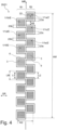
- the Fig. 4 shows a first embodiment of a measuring arrangement 20 according to the invention for X-rays.
- the measuring arrangement 20 has a plurality of detector modules 1, which are arranged here similarly to Fig. 1 shown as semiconductor detector modules with continuous sensor strips for a spatial resolution along the sequence direction of the sensor strips.
- the detector modules 1 form the essential components of an X-ray detector 21 of the Measuring arrangement 20.
- the detector modules 1 are designed to detect X-rays emanating from a sample position; for the sake of simplicity, the sample position is not shown in detail here (but see Figs. 12 -14 here).
- All detector modules 1 are arranged individually one after the other with respect to a (provided) measuring direction MR, ie each detector module 1 is arranged at a different location with respect to the measuring direction MR (the location of a detector module 1 can be defined, for example, via the center 22 of the detector module 1). From top to bottom in Fig. 4 the detector modules 1 are arranged with respect to the measuring direction MR in the sequence 1a, 1b, 1c, 1d, 1e, 1f, etc.
- All detector modules 1 are constructed identically, each with an active zone 3 that has a length L1 in the measuring direction MR, and with a dead zone 6 that surrounds the active zone 3 like a frame.
- the detector modules 1 each have a length LM in the measuring direction MR.
- the active zones 3 each contain sensor strips of the same width, each of which contains only one continuous sensor element and is aligned transversely to the measuring direction MR.
- the detector modules 1, 1a-1f form a first row R1 and a second row R2.
- the detector modules 1b, 1d, 1f, etc. (“first detector modules” E) are arranged one behind the other in the measuring direction MR and in the same position with respect to the transverse direction QR.
- the detector modules 1a, 1c, 1e, etc. (“second detector modules” Z) are arranged one behind the other in the measuring direction MR and in the same position with respect to the transverse direction QR.
- the two rows R1, R2 are next to each other with respect to the transverse direction QR.
- successive detector modules such as detector modules 1a, 1b
- overlapping area 23a there is a Measuring direction MR both a part of the detector module 1a and a part of the detector module 1b.
- Further overlapping areas 23b, 23c, 23d and 23e are formed by the detector module pairs 1b/1c, 1c/1d, 1d/1e and 1e/1f.
- the active zones 3 of the detector modules 1 of a respective overlapping area 23a-23e do not overlap with respect to the measuring direction MR, but the active zones 3 are directly adjacent to one another with respect to the measuring direction MR (even if the adjacent active zones 3 are arranged at different positions in the transverse direction QR, corresponding to the different positions of the rows R1, R2 in the transverse direction QR).
- the detector modules overlapping in an overlapping region, such as the overlapping region 23a, in the measuring direction MR, such as the detector modules 1a and 1b, do not overlap in the transverse direction, i.e. at each position along the transverse direction only the detector module 1a or the detector module 1b can be found, but not both.
- both rows R1, R2 are designed as spaced rows in which the detector modules following one another in the measuring direction MR, such as the detector modules 1a, 1c in the second row R2, have a distance AB with respect to the measuring direction MR.
- the active zones 3 of the detector modules 1 arranged in a respective row R1, R2 each have a distance L2 in the measuring direction MR.
- X-rays originating from a measurement sample at the sample position hit the X-ray detector 21.
- X-rays containing the same information from the measurement sample illuminate the entire extent AQ of the X-ray detector equally. Therefore, it does not matter whether measurement information (or X-ray intensity) for a specific (measurement) position along the measurement direction MR is measured by a detector module 1b, 1d, 1f etc. of the first row R1 or by a detector module 1a, 1c, 1e of the second row R2.
- the measuring information can be obtained over the entire extent AM of the X-ray detector 21.
- the measuring information can be obtained by means of an active zone 3 of a detector module 1a, 1c, 1e in the second row R2 and vice versa.
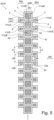
- the Fig. 5 shows a second embodiment of a measuring arrangement 20 according to the invention; only the essential differences to the embodiment of Fig. 4 explained.
- the detector modules 1 are arranged in three rows, namely a central, first row R1 (with detector modules 1a, 1d, 1g, etc., "first detector modules” E), and two second rows R2a, R2b (with detector modules 1b, 1e and 1c, 1f, "second detector modules” Z).
- the detector modules 1 are arranged here in an alternating sequence of individual detector modules 1 of the first row R1 and groups of two detector modules 1 from the second rows R2a, R2b in succession with respect to the measuring direction MR. From top to bottom in Fig.
- the detector modules 1 are arranged with respect to the measuring direction MR in the sequence individual detector module 1a, group of detector modules 1b, 1c, individual detector module 1d, group of detector modules 1e, 1f, individual detector module 1g, etc.
- the detector modules 1a, 1d, 1g of the first row (“first detector modules” E) are larger here than the detector modules 1b, 1c, 1e, 1f of the second rows R2a, R2b ("second detector modules" Z).
- the first row R1 is not designed as a spaced row here, since the detector modules 1a, 1d, 1g of the first row R1 are directly adjacent to one another.
- the second rows R2a, R2b are spaced rows, with a distance L2 between successive active zones 3 of the detector modules 1b, 1e in the measuring direction MR, and a distance AB between the successive detector modules 1b, 1e in the measuring direction MR.
- L1 length of the active zones 3 of the detector modules 1a, 1d, 1g of the first row R1.
- the active zones 3 of the groups of detector modules 1b/1c and 1e/1f of the second rows R2a, R2b bridge the dead zones 6 of the detector modules 1a, 1d, 1g that follow one another in the first row R1.
- the active zones 3 of the detector modules 1a, 1d, 1g of the first row R1 bridge the dead zones 6 of the detector modules 1b, 1e and 1c, 1f and the gaps between the detector modules 1b, 1e and 1c, 1f of the second rows R2a, R2b in the measuring direction MR.
- the group 1b/1c of detector modules of the second rows R2a, R2b has the overlapping areas 23a (to the detector module 1a of the row R1) and 23b (to the detector module 1d of the row R1), in which the detector modules 1b/1c overlap with the detector module 1a (overlap area 23a) and the detector modules 1b/1c overlap with the detector module 1d (in the overlap area 23b) in the measuring direction MR; however, there is again no overlap of the detector modules (e.g. 1a, 1b, 1c) of an overlapping area (e.g. 23a) in the transverse direction QR.
- the sensor strips 4c, 4d of the detector modules 1b, 1e, 1c, 1f in the second rows R2a, R2b have a width (in the transverse direction QR) that is half the width of the sensor strips 4a of the detector modules 1a, 1d in the first row. Since in the bridging groups 1b, 1c and 1e, 1f of detector modules in the second rows R2a, R2b two sensor strips 4c, 4d read the same position along the measuring direction MR simultaneously, but in the detector modules 1a, 1d, 1g of the first row R1 only one sensor strip 4a, the same effective total sensor length SL and thus integration area for X-rays results in both cases.
- the Fig. 6 shows a third embodiment of a measuring arrangement 20 similar to that in Fig. 5 shown measuring arrangement. Again, only the essential differences are explained.
- the sensor strips 4a, 4c, 4d of the detector modules 1 are each divided again in the transverse direction QR into pixel-shaped sensor elements 30.
- This enables a spatially resolved intensity determination of X-rays not only along the measuring direction MR, but also along the transverse direction QR.
- the division in the transverse direction QR is used to reduce an effective width of the entirety of the active zones 3 in the transverse direction QR, within which detected X-rays are evaluated ("virtual mask"), in order to reduce the influence of scattered radiation or to be able to carry out a scan of the X-ray detector 21 along the transverse direction QR with greater local sharpness.
- Fig. 7 shows a fourth embodiment of a measuring arrangement 20 according to the invention, similar to that in Fig. 4 shown measuring arrangement. The main differences are again explained.
- the detector modules 1 are arranged one after the other in only one row R in the measuring direction MR; all detector modules 1 are of the same design and (in the row R) are oriented the same.
- the detector modules 1 are arranged in an interlocking manner, i.e. a projection 43, 44 (with respect to the measuring direction MR) of a respective detector module 1 engages in a recess 45, 46 (with respect to the measuring direction MR) of the other detector module 1 and vice versa (cf. detector modules 1a, 1b).
- the detector modules 1 are designed in an S-shape for this purpose.
- the projections 43, 44 of the detector modules 1 following one another in the measuring direction MR lie next to one another in the transverse direction QR.
- Each detector module 1 comprises two active zones 3a, 3b, which overlap in a central region 40 in the measuring direction MR.
- Detector modules 1a, 1b following one another in the measuring direction MR each form an overlap region 23a in which the detector modules 1a, 1b overlap in the measuring direction MR.
- the active zones (3b of detector module 1a and 3a of detector module 1b) of the various detector modules 1a, 1b also overlap in the measuring direction, so that double measuring regions 41 are formed in the overlap regions 23a.
- the overlapping detector modules 1a, 1b of an overlap region 23a also overlap in the transverse direction QR, ie at a certain position along the transverse direction QR both the detector module 1a and the detector module 1b can be found (although one of them is outside the overlap region 23a, relative to a certain position in the transverse direction QR).
- Fig. 8 shown fifth embodiment of a measuring arrangement according to the invention, which in turn corresponds to the embodiment of Fig. 7 similar, so only the most important differences are explained,
- the detector modules 1 are all constructed identically, each with a large active zone 3a (main active zone) and two small active zones (secondary active zones, with half the width of the sensor strips in the transverse direction QR, but the same length in the measuring direction MR) 3b, 3c, whereby the active zones 3a, 3b, 3c of a detector module 1 adjoin one another in the measuring direction MR, but are offset from one another with respect to the transverse direction QR.
- the detector modules 1 are essentially trapezoidal in shape. The location of a respective detector module 1 can, for example, be described by the center 22 of the large active zone 3a.
- the detector modules 1 are arranged one after the other in the measuring direction MR, with the centers 22 of the successive detector modules 1 one below the other, so that the detector modules 1 are arranged one behind the other in a single row R in this respect; However, the orientation of the detector modules 1 alternates between successive detector modules 1a, 1b, so that the small active zones 3b, 3c are each on different sides (left or right in Fig. 8 ) are positioned towards each other.
- the successive detector modules 1a, 1b are facing each other with wedge-shaped edges 50, 51 (Note that if the location of the detector modules 1 is defined differently, for example at the centroid of the respective detector modules, which are in Fig. 8 embodiment shown could also be understood as comprising two rows).
- the offset of the successive detector modules 1a, 1b in the measuring direction MR is determined such that in a respective overlap area 23a the active zones 3c (of the upper detector module 1a) and 3b (of the lower detector module 1b) overlap exactly in the measuring direction. This ensures that at every position along the measuring direction MR the same effective, total strip length SL is available in the transverse direction or on the sensor surface.
- the overlapping detector modules 1a, 1b of an overlapping region 23a also overlap in the transverse direction QR, i.e. at a certain position along the transverse direction QR both the detector module 1a and the detector module 1b can be found (partially with both detector modules 1a, 1b in the overlapping region 23a, based on a certain position in the transverse direction QR).
- the lower and upper parts of the overlapping detector modules 1a, 1b lie next to each other in the transverse direction QR.
- FIG. 9 The sixth embodiment of a measuring arrangement 20 according to the invention shown is similar to the embodiment of Fig. 8 so that only the essential differences are explained.
- the essentially trapezoidal detector modules 1 are in turn arranged one behind the other in a row R, with the orientation of the detector modules 1 alternating between successive detector modules 1a, 1b.
- Each detector module 1 has an active zone 3 with sensor strips 4a, 4b, with the sensor strips 4a having a uniform sensor element width SEB in a central region 60; the sensor strips 4a, 4b each contain only one continuous sensor element 30.
- the location of a detector module 1 can be determined via the center 22 of a respective central region 60 (here neglecting the at the upper and lower edge of the sensor strips 4a, which are already slightly offset in the transverse direction. (Note that if the location of the detector modules 1 is defined differently, for example at the center of gravity of the respective detector modules, which are in Fig. 9 shown embodiment could also be understood as comprising two rows).
- the successive detector modules 1a, 1b overlap in the measuring direction MR in overlapping areas 23a, whereby the active zones 3 also overlap in double measuring areas 41.
- the local sensor element widths of the sensor strips 4b of the active zones 3 are shortened, whereby at a respective position along the measuring direction MR, the sum of the sensor element widths of the sensor strips 4b of the two active zones 3 of the detector modules 1a, 1b results in a summed effective strip length SL in the transverse direction QR, whereby SL is equal to the uniform sensor element width SEB of the individual sensor strips 4a in the middle area 60.
- FIG. 10 A seventh embodiment of a measuring arrangement 20 according to the invention is shown in Fig. 10 Only the essential differences to the design of Fig. 9 explained.
- the detector modules 1 are again arranged in a row one behind the other. Overlap areas 23a of adjacent detector modules 1a, 1b are set up in the area of wedge-shaped edges 50, 51.
- the active zones 3 of the detector modules 1a, 1b also overlap in double measuring areas 41. In the double measuring areas 41, the sensor strips 4b are again shortened, with the summed, effective strip lengths SL in the transverse direction QR being the same everywhere.
- all detector modules 1 are identically designed and are oriented in the same way in the sequence of detector modules 1 in row R.
- the detector modules 1 are each designed like a parallelogram.
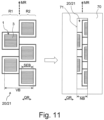
- the Fig. 11 shows a section of a measuring arrangement 20 according to the invention as in Fig. 4 which is covered with a mask 70. On the left is the measuring arrangement 20 alone, and on the right is the measuring arrangement 20 with the mask 70 positioned in front of it.
- the mask 70 is made of a material that is poorly permeable to X-rays, such as lead.
- the entirety of the active areas 3 of the detector modules 1 in both rows R1, R2 has a full width VB in the transverse direction QR.
- the full width VB of the entirety of the active areas 3 is limited to a smaller, then still usable width NB in the transverse direction QR.
- only about 1 ⁇ 4 of the respective sensor element width SEB (or strip length) remains unshaded in the transverse direction QR.
- the mask 70 is positioned in such a way that parts of the active zones 3 remain equally unshaded in both rows R1, R2 (or the detector modules 1 overlapping in the overlapping areas with respect to the measuring direction MR), i.e. a gapless X-ray measurement with respect to the measuring direction MR can also be carried out with mask 70.
- the mask 70 can be used to perform a more precise X-ray diffraction measurement with respect to the transverse direction QR, for example if the X-ray detector 21 is pivoted/rotated during the measurement (for example, to determine mechanical stresses or preferred directions/textures in the measurement sample).
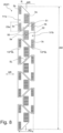
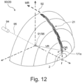
- the Fig. 12 shows a measuring setup 90 for the invention, comprising a measuring arrangement 20 according to the invention, similar to Fig. 9 shown.
- An X-ray beam 95 is directed from an X-ray source 94 onto a sample position 91 at which a measurement sample 96 is arranged.
- the measurement sample 96 interacts with the X-ray radiation, in particular by diffraction at the lattice structures in the material of the measurement sample 96.
- the measurement sample 96 is, for example, powder-shaped, so that diffracted radiation emanates from the measurement sample in so-called Debye cones, with the axis of the Debye cones corresponding to the direction of propagation of the X-ray beam 95.
- Possible intersection rings of Debye cones around a sphere around the sample position 91, here with a radius corresponding to the circular arc 92, are indicated by dotted lines ("Debye rings").
- the detector modules 1 of an X-ray detector 21 are arranged on a circular arc 92 around the sample position 91.
- the detector modules 1 are arranged overlapping along the circular arc 92, which simultaneously defines the (local) measuring direction MR at each detector module 1 (as described above).
- the individual detector modules 1 are each formed on a flat substrate 2, which is oriented perpendicular to the local connection direction VR to the sample position 91 (shown as an example for detector module 1a).
- the local connection direction VR runs from the sample position 91 to the respective substrate 2 or to the detector module 1 (or its center).
- the measuring direction MR, the transverse direction QR and the connection direction VR are approximately perpendicular to one another.
- the long direction of the X-ray beam should be parallel to the transverse direction QR and the short direction perpendicular to it (here in the vertical direction) in order to establish the redundancy of the measurement information along the transverse direction implicit in the extended X-ray beam.
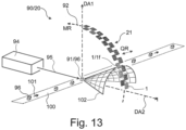
- the Fig. 13 illustrates a possible application of a measurement setup 90, similar to Fig. 12 shown.
- various measurement samples 96 run along a conveying direction 101 towards the sample position 91; a measurement sample 96 has just arrived at the sample position 91.
- the X-ray beam 95 irradiates the measurement sample 96 at the sample position 91 for a short time (corresponding to the speed of the conveyor belt 100), and diffracted X-rays belonging to the measurement sample 96 are registered at the X-ray detector 21 of the measuring arrangement 20. For example, diffracted X-rays of the Debye cone 102 are measured at the detector module 1f.
- a gapless, one-dimensional diffraction information is obtained from the measurement sample 96 over the entire section of the circular arc 92 covered by the detector modules 1 overlapping in the measuring direction MR; all detector modules 1 measure simultaneously. In particular, it is not necessary to move the X-ray detector 21 in order to obtain gapless diffraction information.
- crystalline impurities in a measurement sample 96 can be detected quickly and easily using the diffraction information, for example in order to sort them out from a production process if contamination is present.
- the X-ray source 94 and the X-ray detector 21 are arranged in a stationary manner, which is particularly easy to set up.
- the pivotability about an axis of rotation DA1 or DA2 enables stress measurements or texture measurements to be carried out on the measurement sample 96. If the X-ray detector 21 is rotated during the measurement, an X-ray beam 95 with a point focus is preferred, although a mask can also be used if necessary.
- the Fig. 14 shows in schematic side view a third measuring setup 90 for general explanation, comprising a measuring arrangement 20 similar to that in Fig. 4
- the measuring arrangement 20 comprises an X-ray detector 21 with several detector modules 1, which are arranged in two rows overlapping with respect to the measuring direction MR (as described above); detector modules 1a of the first row are shown in dashed lines, and detector modules 1b in the second row are shown in dotted lines.
- the first and second rows are arranged one behind the other in the transverse direction (which here runs perpendicular to the plane of the drawing).
- the detector modules 1 register diffracted X-rays from a measurement sample 96 at the sample position 91, which is illuminated by an X-ray beam 95 from an X-ray source 94.
- the measuring direction MR along which the detector modules 1 are arranged in succession and along which the X-ray detector provides a spatial resolution, runs here along a straight line that is oriented vertically in the design shown.
- This design is particularly simple and allows a flexible change in the distance 110 between the sample position 91 or measurement sample 96 and the X-ray detector 21 (measured here along the propagation direction of the X-ray beam 95).
- the transverse direction (running perpendicular to the plane of the drawing) at each detector module 1 runs perpendicular to the local measuring direction MR and perpendicular to the local connection direction to the sample position; however, the local measuring direction MR runs with sometimes considerable deviations from a 90° angle compared to the local connection direction to the sample position 91.
- a typical distance 110 between sample position 96 and X-ray detector 21 is 150-300 mm.
- Typical dimensions AQ of the entire active zones in the transverse direction are 5-20 mm.
- the energy of the X-rays used is usually around 4-30 keV, for special applications up to 60 keV or even up to 150 keV.
- detector modules are arranged one after the other in the measuring direction and next to one another in the transverse direction, and in particular not one behind the other with respect to the connection direction to the sample position.
- the present invention proposes to design an X-ray detector (21) with a plurality of detector modules (1, 1a-1g), each of which has dead zones (6) without X-ray sensitivity and active zones (3, 3a-3c) with Measuring direction (MR) spatially resolved X-ray sensitivity, wherein the detector modules (1, 1a-1g) are designed to follow one another and overlap along the measuring direction (MR), so that in overlapping regions (23a-23e) the dead zone (6) of a detector module (1, 1a-1g) is bridged by an active zone (3, 3a-3c) of another detector module (1, 1a-1g).
- MR Measuring direction
- the overlapping detector modules (1, 1a-1g) are arranged next to one another in the transverse direction (QR) in the overlapping regions (23a-23e), wherein the transverse direction (QR) runs transversely to the local measuring direction (MR) and transversely to a local connection direction (VR) to a sample position (91).
- the X-ray detector (21) makes it easy to obtain seamless, one-dimensional measurement information, namely X-ray diffraction information, from a measurement sample (96) at the sample position (91).
Landscapes
- Chemical & Material Sciences (AREA)
- Crystallography & Structural Chemistry (AREA)
- Physics & Mathematics (AREA)
- Health & Medical Sciences (AREA)
- Life Sciences & Earth Sciences (AREA)
- Analytical Chemistry (AREA)
- Biochemistry (AREA)
- General Health & Medical Sciences (AREA)
- General Physics & Mathematics (AREA)
- Immunology (AREA)
- Pathology (AREA)
- Analysing Materials By The Use Of Radiation (AREA)
- Measurement Of Radiation (AREA)
Claims (17)
- Dispositif de mesure (20) pour une diffraction de rayons X, comprenant- une position d'échantillon (91) pouvant être éclairée par faisceau de rayons X (95), et- un détecteur de rayons X (21) pour une détection de rayons X provenant de la position d'échantillon (91), comprenant plusieurs modules de détecteur (1, 1a-1g), les modules de détecteur (1, 1a-1g) présentant chacun au moins une zone active (3, 3a-3c) dans laquelle des rayons X peuvent être détectés, et une zone inactive (6) dans laquelle aucun rayon X ne peut être détecté, et qui entoure ladite au moins une zone active (3, 3a-3c),les modules de détecteur (1, 1a-1g) étant agencés individuellement et/ou en groupes successifs par rapport à une direction de mesure (MR),les zones actives (3, 3a-3c) des modules de détecteur (1, 1a-1g) étant chacune conçues pour une détection des rayons X par résolution locale dans la direction de mesure (MR),l'ensemble des zones actives (3, 3a-3c) de tous les modules détecteurs (1, 1a-1g) du détecteur de rayons X (21) présentant une extension AM dans la direction de mesure (MR) et une extension AQ dans une direction transversale (QR), avec AM ≥ 5*AQ, la direction transversale (QR) étant localement transversale à la direction de mesure (MR) et localement transversale à une direction de liaison (VR) à la position d'échantillon (91),au moins une partie des modules de détecteur (1, 1a-1g) qui se suivent par rapport à la direction de mesure (MR) formant des zones de chevauchement (23a-23e) dans lesquelles au moins deux modules de détecteur (1, 1a-1g) se chevauchent dans la direction de mesure (MR) et sont agencés l'un à côté de l'autre dans la direction transversale (QR),les zones actives (3, 3a-3c) des modules de détecteur (1, 1a-1g) dans les zones de chevauchement (23a-23e) se raccordant directement les unes aux autres dans la direction de mesure (MR) ou se chevauchant dans la direction de mesure (MR), de sorte que l'ensemble des zones actives (3, 3a-3c) des modules de détecteur (1, 1a-1g) permet une mesure complète dans la direction de mesure (MR) des rayons X provenant de la position d'échantillon (91),et les modules de détecteur (1) étant agencés le long d'un arc de cercle (92) se chevauchant autour de la position d'échantillon (91), l'arc de cercle (92) définissant la direction de mesure locale (MR) au niveau de chaque module de détecteur (1), et les modules de détecteur (1, 1a-1g) étant formés chacun sur un substrat plan (2) qui est orienté perpendiculairement à la direction de liaison locale (VR) à la position d'échantillon (96), et au niveau du module de détecteur respectif (1), la direction de mesure (MR), la direction transversale (QR) et la direction de liaison (VR) étant approximativement mutuellement perpendiculaires.
- Dispositif de mesure (20) selon la revendication 1, caractérisé en ce que les modules de détecteur (1, 1a-1g) comprennent des premiers modules de détecteur (E) et des seconds modules de détecteur (Z),les premiers modules de détecteur (E) étant agencés les uns derrière les autres en une première rangée (R1) dans la direction de mesure (MR), et les seconds modules de détecteur (Z) étant agencés les uns derrière les autres en au moins une seconde rangée (R2 ; R2a, R2b) dans la direction de mesure (MR),en ce que la première rangée (R1) et la au moins une seconde rangée (R2 ; R2a, R2b) sont agencés côte à côte par rapport à la direction transversale (QR), et en ce que les premiers modules détecteurs (E) sont agencés décalés les uns par rapport aux autres par rapport aux seconds modules détecteurs (Z) dans la direction de mesure (MR), de sorte que les zones actives (3, 3a-3c) des seconds modules de détecteur (Z) chevauchent dans la direction de mesure (MR) des zones inactives (6) des premiers modules de détecteur (E) qui ne sont pas chevauchées dans la direction de mesure (MR) par des zones actives (3, 3a-3c) des premiers modules de détecteur (E).
- Dispositif de mesure (20) selon la revendication 2, caractérisé en ce que pour une première longueur L1 dans la direction de mesure (MR), sur laquelle s'étendent la zone active (3, 3a-3c) ou les zones actives (3, 3a-3c) d'un premier module de détecteur (1, 1a-1g), et pour une seconde longueur L2 dans la direction de mesure (MR), qui est située entre les zones actives (3, 3a-3c) d'au moins un seconde rangée (R2 ; R2a, R2b) de modules de détecteur (1, 1a-1g) successifs dans la direction de mesure (MR), qui forment ensemble une zone de chevauchement (23a-23e) avec le premier module de détecteur (E), s'applique respectivement : L2 ≥ 0,2*L1, de préférence L2 ≥ 0,4*L1.
- Dispositif de mesure (20) selon l'une quelconque des revendications 2 ou 3, caractérisé en ce que la première rangée (R1) et la au moins une seconde rangée (R2 ; R2a, R2b) comprennent au moins une rangée espacée dans laquelle les modules de détecteur (1, 1a-1g) successifs dans la direction de mesure (MR) sont agencés à une distance AB les uns des autres par rapport à la direction de mesure (MR),
en particulier avec AB ≥ 0,3*LM, avec LM : longueur des modules de détecteur (1, 1a-1g) dans la rangée espacée dans la direction de mesure (MR). - Dispositif de mesure (20) selon la revendication 1, caractérisé en ce que les modules de détecteur (1, 1a-1g) sont agencés les uns derrière les autres en une seule rangée (R) dans la direction de mesure (MR), les modules de détecteur (1, 1a-1g) se chevauchant également dans la direction transversale (QR) dans les zones de chevauchement (23a-23e).
- Dispositif de mesure (20) selon l'une quelconque des revendications précédentes, caractérisé en ce que les modules de détecteur (1, 1a-1g) sont réalisés approximativement en forme de coin et/ou dentés dans les zones de chevauchement (23a-23b).
- Dispositif de mesure (20) selon l'une quelconque des revendications 1 à 6, caractérisé en ce que dans les zones de chevauchement (23a-23e), les zones actives (3 ; 3-3c) des modules de détecteur (1, 1a-1g) qui se chevauchent se chevauchent dans la direction de mesure (MR) dans des zones de mesure doubles (41).
- Dispositif de mesure (20) selon la revendication 7, caractérisé en ce que les zones actives (3, 3a-3c) des modules de détecteur (1, 1a-1g) sont formées raccourcies dans les zones de mesure doubles (41) par rapport à la direction transversale (QR) par comparaison à l'extérieur des zones de mesure doubles (41).
- Dispositif de mesure (20) selon l'une quelconque des revendications 1 à 6, caractérisé en ce que, dans les zones de chevauchement (23a-23e), les zones actives (3, 3a-3c) des modules de détecteur (1, 1a-1g) qui se chevauchent ne se chevauchent pas dans la direction de mesure (MR).
- Dispositif de mesure (20) selon l'une quelconque des revendications précédentes, caractérisé en ce que la au moins une zone active (3, 3a-3c) d'un module de détecteur respectif (1, 1a-1g) présente plusieurs bandes de capteur (4a-4d) qui se suivent dans la direction de mesure (MR) et qui s'étendent au moins sensiblement dans la direction transversale (QR).
- Dispositif de mesure (20) selon la revendication 10, caractérisé en ce qu'à toutes les positions le long de la direction de mesure (MR), une longueur de bande effective additionnée (SL) dans la direction transversale (QR) des bandes de capteur (4a-4d) de tous les modules de détecteur (1, 1a-1g) qui forment une bande de capteur (4a-4d) à la position respective est identique.
- Dispositif de mesure (20) selon la revendication 10 ou 11, caractérisé en ce qu'au moins une partie des bandes de capteur (4a-4d), de préférence chaque bande de capteur (4a-4d), présente au moins un élément de capteur (30) qui présente un rapport d'aspect d'élément de capteur SEAV ≥ 3, SEAV = SEB/SEH et SEB : largeur de l'élément capteur (30) dans la direction transversale (QR), et SEH : hauteur de l'élément capteur (30) dans la direction de mesure (MR).
- Dispositif de mesure (20) selon l'une quelconque des revendications 10 à 12, caractérisé en ce que les bandes de capteur (4a-4d) sont réalisés de forme approximativement rectangulaire, les côtés longitudinaux (5) des bandes de capteur (4a-4d) s'étendant dans la direction transversale (QR), et les bandes de capteur (4a-4d) successives d'une zone active respective (3, 3a-3c) dans la direction de mesure (MR) s'appliquant les unes contre les autres par leurs côtés longitudinaux (5).
- Dispositif de mesure (20) selon l'une quelconque des revendications précédentes, caractérisé en ce que :dans les zones de chevauchement (23a-23e), les zones actives (3 ; 3-3c) des modules détecteurs se chevauchant (1, 1a-1g) se chevauchent dans la direction de mesure (MR) dans les zones de mesure doubles (41),les zones actives (3, 3a-3c) des modules de détecteur (1, 1a-1g) dans les zones de mesure doubles (41) sont raccourcies par rapport à la direction transversale (QR) par comparaison à l'extérieur des zones de mesure doubles (41),la au moins une zone active (3, 3a-3c) d'un module de détecteur (1, 1a-1g) respectif présente plusieurs bandes de capteur (4a-4d) qui se suivent dans la direction de mesure (MR) et qui s'étendent au moins essentiellement dans la direction transversale (QR),et en ce qu'à toutes les positions le long de la direction de mesure (MR), une longueur de bande effective additionnée (SL) dans la direction transversale (QR) des bandes de capteur (4a-4d) de tous les modules de détecteur (1, 1a-1g) qui forment une bande de capteur (4a-4d) à la position respective est la même.
- Dispositif de mesure (20) selon l'une quelconque des revendications précédentes, caractérisé en ce que les modules de détecteur (1, 1a-1g) sont conçus comme des modules de détecteur à semi-conducteur.
- Dispositif de mesure (20) selon l'une quelconque des revendications précédentes, caractérisé en ce qu'un masque (70) est agencé devant les modules de détecteur (1, 1a-1g), qui masque au moins des surfaces partielles d'au moins une partie des zones actives (3, 3a-3c) des modules de détecteur (1, 1a-1g) par rapport à la position d'échantillon (91) et réduit ainsi une largeur utilisable (NB) de l'ensemble des zones actives (3, 3a-3c) dans la direction transversale (QR) par rapport à une largeur complète (VB) de l'ensemble des zones actives (3, 3a-3c) sans masquage.
- Utilisation d'un dispositif de mesure (20) selon l'une quelconque des revendications précédentes pour mesurer un échantillon de mesure (96),l'échantillon de mesure (96) étant irradié avec des rayons X (95) et agencé dans la position d'échantillon (91) ou imagé avec une optique à rayons X dans la position d'échantillon (91),et les données de mesure des modules de détecteur (1, 1a-1g), qui ont été mesurés simultanément, sont combinées de manière complète en un ensemble de données de mesure total à une dimension, par rapport aux positions le long de la direction de mesure (MR),les données de mesure d'au moins un autre des modules de détecteur se chevauchant (1, 1a-1g), qui présente une zone active (3, 3a-3c) dans cette position, sont utilisées à des positions le long de la direction de mesure (MR) dans lesquelles seule une zone inactive (6) d'au moins un des modules de détecteur se chevauchant (1, 1a-1g) est située dans une zone de chevauchement (23a-23e) d'au moins deux modules de détecteur (1, 1a-1g), afin de déterminer l'ensemble de données de mesure total continu.
Applications Claiming Priority (2)
| Application Number | Priority Date | Filing Date | Title |
|---|---|---|---|
| DE102019202442.4A DE102019202442A1 (de) | 2019-02-22 | 2019-02-22 | Messanordnung für Röntgenstrahlung für eine spaltfreie 1D-Messung |
| PCT/EP2020/054162 WO2020169559A1 (fr) | 2019-02-22 | 2020-02-18 | Dispositif de mesure de rayonnement x pour une mesure 1d continue |
Publications (2)
| Publication Number | Publication Date |
|---|---|
| EP3928085A1 EP3928085A1 (fr) | 2021-12-29 |
| EP3928085B1 true EP3928085B1 (fr) | 2025-01-01 |
Family
ID=69630318
Family Applications (1)
| Application Number | Title | Priority Date | Filing Date |
|---|---|---|---|
| EP20705958.5A Active EP3928085B1 (fr) | 2019-02-22 | 2020-02-18 | Dispositif de mesure de rayonnement x pour une mesure 1d continue |
Country Status (5)
| Country | Link |
|---|---|
| US (1) | US12031924B2 (fr) |
| EP (1) | EP3928085B1 (fr) |
| CN (1) | CN113454446B (fr) |
| DE (1) | DE102019202442A1 (fr) |
| WO (1) | WO2020169559A1 (fr) |
Families Citing this family (2)
| Publication number | Priority date | Publication date | Assignee | Title |
|---|---|---|---|---|
| WO2025209135A1 (fr) * | 2024-04-01 | 2025-10-09 | 深圳帧观德芯科技有限公司 | Diffractomètre à rayons x |
| CN119596405A (zh) * | 2024-12-20 | 2025-03-11 | 同方威视技术股份有限公司 | 辐射检查系统 |
Family Cites Families (15)
| Publication number | Priority date | Publication date | Assignee | Title |
|---|---|---|---|---|
| US5812629A (en) * | 1997-04-30 | 1998-09-22 | Clauser; John F. | Ultrahigh resolution interferometric x-ray imaging |
| EP1192479B1 (fr) * | 1999-03-15 | 2013-05-29 | Philips Digital Mammography Sweden AB | Dispositif et procede d'imagerie par rayons x |
| SE524380C2 (sv) | 2002-03-12 | 2004-08-03 | Xcounter Ab | Exponeringsstyrning i scannerbaserad detektering av joniserande strålning |
| US7505554B2 (en) * | 2005-07-25 | 2009-03-17 | Digimd Corporation | Apparatus and methods of an X-ray and tomosynthesis and dual spectra machine |
| US7638776B2 (en) * | 2006-08-21 | 2009-12-29 | Endicott Interconnect Technologies, Inc. | Staggered array imaging system using pixilated radiation detectors |
| GB2441578A (en) * | 2006-09-08 | 2008-03-12 | Ucl Business Plc | Phase Contrast X-Ray Imaging |
| DE102009045092A1 (de) | 2008-09-29 | 2010-12-09 | Friedrich-Alexander-Universität Erlangen-Nürnberg | Vorrichtung und Verfahren zur zeitverzögerten Integration auf einem aus mehreren Detektormodulen zusammengesetzten Röntgendetektoren |
| US8183535B2 (en) | 2009-02-11 | 2012-05-22 | Mats Danielsson | Silicon detector assembly for X-ray imaging |
| DE102009036579A1 (de) | 2009-08-07 | 2011-02-17 | Wenzel Volumetrik Gmbh | Röntgendetektorvorrichtung |
| FI124818B (fi) * | 2011-10-06 | 2015-02-13 | Advacam Oy | Hybridipikseli-ilmaisinrakenne ja tämän valmistusmenetelmä |
| CN102599926A (zh) * | 2012-04-13 | 2012-07-25 | 杭州美诺瓦医疗科技有限公司 | 使用多个传感器组成的扫描型探测器 |
| DE102015101902A1 (de) * | 2015-02-10 | 2016-08-11 | Osram Opto Semiconductors Gmbh | Detektor und Lidar-System |
| US9835571B2 (en) * | 2015-10-06 | 2017-12-05 | Shimadzu Corporation | X-ray analyzer |
| DE102016208320B3 (de) | 2016-05-13 | 2017-03-09 | Bruker Axs Gmbh | Vorrichtung zur Sortierung von Materialien, insbesondere Schrottpartikeln, mittels Röntgenfluoreszenz |
| CN109690351B (zh) * | 2016-09-23 | 2022-12-09 | 深圳帧观德芯科技有限公司 | 半导体x射线检测器的封装 |
-
2019
- 2019-02-22 DE DE102019202442.4A patent/DE102019202442A1/de not_active Withdrawn
-
2020
- 2020-02-18 US US17/432,676 patent/US12031924B2/en active Active
- 2020-02-18 CN CN202080015652.6A patent/CN113454446B/zh active Active
- 2020-02-18 EP EP20705958.5A patent/EP3928085B1/fr active Active
- 2020-02-18 WO PCT/EP2020/054162 patent/WO2020169559A1/fr not_active Ceased
Non-Patent Citations (1)
| Title |
|---|
| KENICHI KATO ET AL: "A statistical approach to correct X-ray response non-uniformity in microstrip detectors for high-accuracy and high-resolution total-scattering measurements", JOURNAL OF SYNCHROTRON RADIATION, vol. 26, no. 3, 9 February 2019 (2019-02-09), pages 762 - 773, XP055699293, DOI: 10.1107/S1600577519002145 * |
Also Published As
| Publication number | Publication date |
|---|---|
| CN113454446A (zh) | 2021-09-28 |
| US12031924B2 (en) | 2024-07-09 |
| WO2020169559A1 (fr) | 2020-08-27 |
| CN113454446B (zh) | 2024-06-28 |
| US20220034825A1 (en) | 2022-02-03 |
| DE102019202442A1 (de) | 2020-08-27 |
| EP3928085A1 (fr) | 2021-12-29 |
Similar Documents
| Publication | Publication Date | Title |
|---|---|---|
| EP1241470B1 (fr) | Dispositif de mesure du transfert d'impulsion lors de la diffusion élastique de quantas de rayons x dans la région d' un conteneur à inspecter | |
| DE19604802C2 (de) | Abbildungssystem und Verfahren zum Erzeugen einer Querschnittsabbildung eines Objekts | |
| EP0714037B1 (fr) | Dispositif pour mesurer le spectre de transmission d'impulsions de quanta de rayons dispersés élastiquement | |
| EP1598663B1 (fr) | Procédé et appareil d'analyse aux rayons X avec un Réseau de détecteurs bidemensionnel | |
| DE102010047205B4 (de) | Sekundärkollimator und Verfahren desselben | |
| EP2793056B1 (fr) | Dispositif et procédé de détermination de la composition énergétique d'ondes électromagnétiques | |
| DE102014116670A1 (de) | Verfahren zum Justieren einer optischen Achse für einen Röntgenstrahlanalysator und Röntgenstrahlanalysator | |
| DE102014117251A1 (de) | Röntgentopographievorrichtung | |
| DE102016218920A1 (de) | Dual-Energy-Detektionsvorrichtung, Dual-Energy-Detektionssystem und Dual-Energy-Detektionsverfahren | |
| DE69127957T2 (de) | Ionenstreuungsspektrometer | |
| EP3928085B1 (fr) | Dispositif de mesure de rayonnement x pour une mesure 1d continue | |
| DE10133676B4 (de) | Röntgenfluoreszenz-Dickenprüfer | |
| DE102014116663A1 (de) | Vorrichtung zum Justieren einer optischen Achse für einen Röntgenstrahlenanalysator | |
| EP1647840B1 (fr) | Analyseur radiologique-optique ou neutronique-optique comportant un détecteur à bandes avec une transmission variable de la lumière | |
| DE102004014445B4 (de) | Sekundärkollimator für eine Röntgenstreuvorrichtung sowie Röntgenstreuvorrichtung | |
| DE602004012031T2 (de) | Detektionseinheit zur Röntgenstreumessung | |
| DE3014978A1 (de) | Abbildungseinrichtung mit einem spaltkollimator | |
| DE112015004144B4 (de) | Röntgenstrahlungserzeuger und Röntgenanalysevorrichtung | |
| DE112015004167B4 (de) | Röntgenstrahlungserzeuger und Röntgenanalysevorrichtung | |
| DE19913929A1 (de) | Vorrichtung und Verfahren zum Bestimmen von Eigenschaften einer Materialbahn | |
| DE102019209188B4 (de) | Messanordnung für Röntgenstrahlung mit verminderten Parallax-Effekten | |
| DE10035917B4 (de) | Gerät zur Strahlungsanalyse mit variablem Kollimator sowie variabler Kollimator | |
| DE3024372C2 (de) | Verfahren zur Messung der Verteilung von Einschlüssen in einem Barren durch Elektronenbestrahlung | |
| DE102013219821A1 (de) | Röntgendetektor | |
| EP1233264A1 (fr) | Appareil pour la mesure du spectre de transfer de moment des photons rayons X |
Legal Events
| Date | Code | Title | Description |
|---|---|---|---|
| STAA | Information on the status of an ep patent application or granted ep patent |
Free format text: STATUS: UNKNOWN |
|
| STAA | Information on the status of an ep patent application or granted ep patent |
Free format text: STATUS: THE INTERNATIONAL PUBLICATION HAS BEEN MADE |
|
| PUAI | Public reference made under article 153(3) epc to a published international application that has entered the european phase |
Free format text: ORIGINAL CODE: 0009012 |
|
| STAA | Information on the status of an ep patent application or granted ep patent |
Free format text: STATUS: REQUEST FOR EXAMINATION WAS MADE |
|
| 17P | Request for examination filed |
Effective date: 20210922 |
|
| AK | Designated contracting states |
Kind code of ref document: A1 Designated state(s): AL AT BE BG CH CY CZ DE DK EE ES FI FR GB GR HR HU IE IS IT LI LT LU LV MC MK MT NL NO PL PT RO RS SE SI SK SM TR |
|
| DAV | Request for validation of the european patent (deleted) | ||
| DAX | Request for extension of the european patent (deleted) | ||
| STAA | Information on the status of an ep patent application or granted ep patent |
Free format text: STATUS: EXAMINATION IS IN PROGRESS |
|
| 17Q | First examination report despatched |
Effective date: 20230616 |
|
| P01 | Opt-out of the competence of the unified patent court (upc) registered |
Effective date: 20231117 |
|
| GRAP | Despatch of communication of intention to grant a patent |
Free format text: ORIGINAL CODE: EPIDOSNIGR1 |
|
| STAA | Information on the status of an ep patent application or granted ep patent |
Free format text: STATUS: GRANT OF PATENT IS INTENDED |
|
| INTG | Intention to grant announced |
Effective date: 20240916 |
|
| RAP3 | Party data changed (applicant data changed or rights of an application transferred) |
Owner name: BRUKER AXS SE |
|
| GRAS | Grant fee paid |
Free format text: ORIGINAL CODE: EPIDOSNIGR3 |
|
| GRAA | (expected) grant |
Free format text: ORIGINAL CODE: 0009210 |
|
| STAA | Information on the status of an ep patent application or granted ep patent |
Free format text: STATUS: THE PATENT HAS BEEN GRANTED |
|
| AK | Designated contracting states |
Kind code of ref document: B1 Designated state(s): AL AT BE BG CH CY CZ DE DK EE ES FI FR GB GR HR HU IE IS IT LI LT LU LV MC MK MT NL NO PL PT RO RS SE SI SK SM TR |
|
| REG | Reference to a national code |
Ref country code: GB Ref legal event code: FG4D Free format text: NOT ENGLISH |
|
| REG | Reference to a national code |
Ref country code: CH Ref legal event code: EP |
|
| REG | Reference to a national code |
Ref country code: DE Ref legal event code: R096 Ref document number: 502020010096 Country of ref document: DE |
|
| REG | Reference to a national code |
Ref country code: IE Ref legal event code: FG4D Free format text: LANGUAGE OF EP DOCUMENT: GERMAN |
|
| REG | Reference to a national code |
Ref country code: NL Ref legal event code: FP |
|
| REG | Reference to a national code |
Ref country code: LT Ref legal event code: MG9D |
|
| PG25 | Lapsed in a contracting state [announced via postgrant information from national office to epo] |
Ref country code: FI Free format text: LAPSE BECAUSE OF FAILURE TO SUBMIT A TRANSLATION OF THE DESCRIPTION OR TO PAY THE FEE WITHIN THE PRESCRIBED TIME-LIMIT Effective date: 20250101 |
|
| PG25 | Lapsed in a contracting state [announced via postgrant information from national office to epo] |
Ref country code: PL Free format text: LAPSE BECAUSE OF FAILURE TO SUBMIT A TRANSLATION OF THE DESCRIPTION OR TO PAY THE FEE WITHIN THE PRESCRIBED TIME-LIMIT Effective date: 20250101 |
|
| PG25 | Lapsed in a contracting state [announced via postgrant information from national office to epo] |
Ref country code: ES Free format text: LAPSE BECAUSE OF FAILURE TO SUBMIT A TRANSLATION OF THE DESCRIPTION OR TO PAY THE FEE WITHIN THE PRESCRIBED TIME-LIMIT Effective date: 20250101 |
|
| PG25 | Lapsed in a contracting state [announced via postgrant information from national office to epo] |
Ref country code: IS Free format text: LAPSE BECAUSE OF FAILURE TO SUBMIT A TRANSLATION OF THE DESCRIPTION OR TO PAY THE FEE WITHIN THE PRESCRIBED TIME-LIMIT Effective date: 20250501 Ref country code: NO Free format text: LAPSE BECAUSE OF FAILURE TO SUBMIT A TRANSLATION OF THE DESCRIPTION OR TO PAY THE FEE WITHIN THE PRESCRIBED TIME-LIMIT Effective date: 20250401 |
|
| PG25 | Lapsed in a contracting state [announced via postgrant information from national office to epo] |
Ref country code: HR Free format text: LAPSE BECAUSE OF FAILURE TO SUBMIT A TRANSLATION OF THE DESCRIPTION OR TO PAY THE FEE WITHIN THE PRESCRIBED TIME-LIMIT Effective date: 20250101 |
|
| PG25 | Lapsed in a contracting state [announced via postgrant information from national office to epo] |
Ref country code: LV Free format text: LAPSE BECAUSE OF FAILURE TO SUBMIT A TRANSLATION OF THE DESCRIPTION OR TO PAY THE FEE WITHIN THE PRESCRIBED TIME-LIMIT Effective date: 20250101 Ref country code: PT Free format text: LAPSE BECAUSE OF FAILURE TO SUBMIT A TRANSLATION OF THE DESCRIPTION OR TO PAY THE FEE WITHIN THE PRESCRIBED TIME-LIMIT Effective date: 20250502 |
|
| PG25 | Lapsed in a contracting state [announced via postgrant information from national office to epo] |
Ref country code: BG Free format text: LAPSE BECAUSE OF FAILURE TO SUBMIT A TRANSLATION OF THE DESCRIPTION OR TO PAY THE FEE WITHIN THE PRESCRIBED TIME-LIMIT Effective date: 20250101 Ref country code: GR Free format text: LAPSE BECAUSE OF FAILURE TO SUBMIT A TRANSLATION OF THE DESCRIPTION OR TO PAY THE FEE WITHIN THE PRESCRIBED TIME-LIMIT Effective date: 20250402 |
|
| PG25 | Lapsed in a contracting state [announced via postgrant information from national office to epo] |
Ref country code: CZ Free format text: LAPSE BECAUSE OF FAILURE TO SUBMIT A TRANSLATION OF THE DESCRIPTION OR TO PAY THE FEE WITHIN THE PRESCRIBED TIME-LIMIT Effective date: 20250101 |
|
| PG25 | Lapsed in a contracting state [announced via postgrant information from national office to epo] |
Ref country code: SE Free format text: LAPSE BECAUSE OF FAILURE TO SUBMIT A TRANSLATION OF THE DESCRIPTION OR TO PAY THE FEE WITHIN THE PRESCRIBED TIME-LIMIT Effective date: 20250101 |
|
| REG | Reference to a national code |
Ref country code: CH Ref legal event code: PL |
|
| REG | Reference to a national code |
Ref country code: DE Ref legal event code: R097 Ref document number: 502020010096 Country of ref document: DE |
|
| PG25 | Lapsed in a contracting state [announced via postgrant information from national office to epo] |
Ref country code: SM Free format text: LAPSE BECAUSE OF FAILURE TO SUBMIT A TRANSLATION OF THE DESCRIPTION OR TO PAY THE FEE WITHIN THE PRESCRIBED TIME-LIMIT Effective date: 20250101 |
|
| PG25 | Lapsed in a contracting state [announced via postgrant information from national office to epo] |
Ref country code: DK Free format text: LAPSE BECAUSE OF FAILURE TO SUBMIT A TRANSLATION OF THE DESCRIPTION OR TO PAY THE FEE WITHIN THE PRESCRIBED TIME-LIMIT Effective date: 20250101 |
|
| PG25 | Lapsed in a contracting state [announced via postgrant information from national office to epo] |
Ref country code: MC Free format text: LAPSE BECAUSE OF FAILURE TO SUBMIT A TRANSLATION OF THE DESCRIPTION OR TO PAY THE FEE WITHIN THE PRESCRIBED TIME-LIMIT Effective date: 20250101 |
|
| PG25 | Lapsed in a contracting state [announced via postgrant information from national office to epo] |
Ref country code: IT Free format text: LAPSE BECAUSE OF FAILURE TO SUBMIT A TRANSLATION OF THE DESCRIPTION OR TO PAY THE FEE WITHIN THE PRESCRIBED TIME-LIMIT Effective date: 20250101 Ref country code: LU Free format text: LAPSE BECAUSE OF NON-PAYMENT OF DUE FEES Effective date: 20250218 |
|
| PG25 | Lapsed in a contracting state [announced via postgrant information from national office to epo] |
Ref country code: CH Free format text: LAPSE BECAUSE OF NON-PAYMENT OF DUE FEES Effective date: 20250228 |
|
| PG25 | Lapsed in a contracting state [announced via postgrant information from national office to epo] |
Ref country code: EE Free format text: LAPSE BECAUSE OF FAILURE TO SUBMIT A TRANSLATION OF THE DESCRIPTION OR TO PAY THE FEE WITHIN THE PRESCRIBED TIME-LIMIT Effective date: 20250101 |
|
| PG25 | Lapsed in a contracting state [announced via postgrant information from national office to epo] |
Ref country code: RO Free format text: LAPSE BECAUSE OF FAILURE TO SUBMIT A TRANSLATION OF THE DESCRIPTION OR TO PAY THE FEE WITHIN THE PRESCRIBED TIME-LIMIT Effective date: 20250101 |
|
| PG25 | Lapsed in a contracting state [announced via postgrant information from national office to epo] |
Ref country code: SK Free format text: LAPSE BECAUSE OF FAILURE TO SUBMIT A TRANSLATION OF THE DESCRIPTION OR TO PAY THE FEE WITHIN THE PRESCRIBED TIME-LIMIT Effective date: 20250101 |
|
| PLBE | No opposition filed within time limit |
Free format text: ORIGINAL CODE: 0009261 |
|
| STAA | Information on the status of an ep patent application or granted ep patent |
Free format text: STATUS: NO OPPOSITION FILED WITHIN TIME LIMIT |
|
| REG | Reference to a national code |
Ref country code: BE Ref legal event code: MM Effective date: 20250228 |
|
| 26N | No opposition filed |
Effective date: 20251002 |
|
| PG25 | Lapsed in a contracting state [announced via postgrant information from national office to epo] |
Ref country code: BE Free format text: LAPSE BECAUSE OF NON-PAYMENT OF DUE FEES Effective date: 20250228 |
|
| PG25 | Lapsed in a contracting state [announced via postgrant information from national office to epo] |
Ref country code: IE Free format text: LAPSE BECAUSE OF NON-PAYMENT OF DUE FEES Effective date: 20250218 |
|
| PGFP | Annual fee paid to national office [announced via postgrant information from national office to epo] |
Ref country code: NL Payment date: 20260218 Year of fee payment: 7 |
|
| PGFP | Annual fee paid to national office [announced via postgrant information from national office to epo] |
Ref country code: GB Payment date: 20260219 Year of fee payment: 7 |
|
| PGFP | Annual fee paid to national office [announced via postgrant information from national office to epo] |
Ref country code: DE Payment date: 20260217 Year of fee payment: 7 |
|
| PG25 | Lapsed in a contracting state [announced via postgrant information from national office to epo] |
Ref country code: AT Free format text: LAPSE BECAUSE OF NON-PAYMENT OF DUE FEES Effective date: 20250218 |
|
| REG | Reference to a national code |
Ref country code: AT Ref legal event code: MM01 Ref document number: 1756710 Country of ref document: AT Kind code of ref document: T Effective date: 20250218 |
|
| PGFP | Annual fee paid to national office [announced via postgrant information from national office to epo] |
Ref country code: FR Payment date: 20260223 Year of fee payment: 7 |