EP0714848A2 - Ascenseur pour le levage de charges dans ou sur un bâtiment - Google Patents
Ascenseur pour le levage de charges dans ou sur un bâtiment Download PDFInfo
- Publication number
- EP0714848A2 EP0714848A2 EP95116385A EP95116385A EP0714848A2 EP 0714848 A2 EP0714848 A2 EP 0714848A2 EP 95116385 A EP95116385 A EP 95116385A EP 95116385 A EP95116385 A EP 95116385A EP 0714848 A2 EP0714848 A2 EP 0714848A2
- Authority
- EP
- European Patent Office
- Prior art keywords
- elevator according
- building
- elevator
- conductor
- cable
- Prior art date
- Legal status (The legal status is an assumption and is not a legal conclusion. Google has not performed a legal analysis and makes no representation as to the accuracy of the status listed.)
- Granted
Links
- 239000004020 conductor Substances 0.000 claims description 44
- 239000000463 material Substances 0.000 claims description 32
- 238000010276 construction Methods 0.000 description 4
- 239000000725 suspension Substances 0.000 description 2
- 241001626506 Philypnodon Species 0.000 description 1
- XAGFODPZIPBFFR-UHFFFAOYSA-N aluminium Chemical compound [Al] XAGFODPZIPBFFR-UHFFFAOYSA-N 0.000 description 1
- 229910052782 aluminium Inorganic materials 0.000 description 1
- 230000015572 biosynthetic process Effects 0.000 description 1
- 230000005484 gravity Effects 0.000 description 1
- 238000009418 renovation Methods 0.000 description 1
- 230000008439 repair process Effects 0.000 description 1
Images


Classifications
-
- B—PERFORMING OPERATIONS; TRANSPORTING
- B66—HOISTING; LIFTING; HAULING
- B66B—ELEVATORS; ESCALATORS OR MOVING WALKWAYS
- B66B9/00—Kinds or types of lifts in, or associated with, buildings or other structures
- B66B9/16—Mobile or transportable lifts specially adapted to be shifted from one part of a building or other structure to another part or to another building or structure
Definitions
- the invention relates to an elevator according to the preamble of the main claim.
- the invention has for its object to provide an elevator that can be transported with a commercially available transport vehicle that can still be quickly set up without additional aids and requires little space and that finally allows transporting the loads to be transported into the building without the inclination of the elevator being required.
- the invention further relates to the formation of a special material slide with which it is possible to transport the window intended for this window opening through a window opening, the window frame of the window naturally having outer dimensions that are larger than the inner dimensions of the window.
- an elevator which is formed from individual, intermeshable conductor sections which are of such a size that they can be easily transported on or in a so-called bulli.
- the upper, outer end of the actual elevator opposite the ladder foot is formed by a ladder section, which can also be designed as an acceptance table and to which the drive is attached, the connection between this end ladder section and the vertical ladder being formed by a deflection bend, which is also can be easily inserted by hand.
- the engine can be conveniently run by one Person are carried into the building and a cable is connected to it, which leads at the other end to a material sled on the ladder sections. It is not necessary to redirect the cable as previously in construction lifts.
- a return cable - preferably a rubber cable - is provided in the upper area of the elevator, which is tensioned by the retracting material hoist pulled by the cable hoist and thus, when the material hoist is unloaded, pulls the material hoist back until it tightens itself on the vertical conductor sections due to its weight drives down.
- the individual, intermeshable conductor sections are locked against unintentional loosening and can be pushed by one person from below, since they are made of aluminum and the entire elevator is accordingly designed to be light.
- the construction of the elevator from bottom to top is supported by the motor connected to the acceptance table and the cable that pulls up the connected conductor sections, for which purpose an additional extension arm is provided at the outer end of the conductor section reaching into the building.
- the last step is to set up the ladder foot in front of the building, which compensates for ground inclinations due to a ball and socket joint provided between the ladder foot and the floor support plate and enables height adjustments due to its telescopic design.
- the actual material carriage has a loading platform which can be pivoted with respect to the longitudinal axis of the material carriage and thus also the longitudinal axis of the material carriage and thus also the longitudinal axis of the individual conductor sections.
- the swiveling can range up to 90 °. This ensures that the frame mounted on the loading platform can be easily passed through the window opening, although the outer dimensions of the frame are larger than the inner dimensions of the window openings.
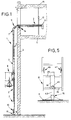
- an elevator 1 is shown, which is arranged in front of a building wall 3 and leads into the building through a window opening 4, a ceiling 15 and a floor 5 being shown within the building.
- the actual elevator 1 consists of individual conductor sections 2, which (FIG. 3) are each formed from conductor struts 24 and 25, between which rungs 26 are arranged, which serve to connect the conductor struts 24 and 25 and keep these conductor struts at a distance.
- the individual conductor sections 2 connect to the bottom of a conductor foot 10, which is supported with the interposition of a ball joint 16 on a floor support plate 9, so that it is possible to compensate for ground inclinations, while the individual conductor sections 2 of the elevator 1 are aligned essentially vertically.
- the ladder foot 10 is also - as this is particularly clearly shown in FIG. 5 - designed telescopically, i. H. upwards adjoins the ball joint 16 a support strut 43 which is arranged displaceably in a telescopic tube 44, the telescopic tube 44 being fixedly arranged on the conductor struts 24.
- the position of the support strut 43 within the telescopic tube 44 can be locked by a locking means 45. With 46 and 47 locking means are indicated, which serve to firmly connect the individual conductor sections 2 to each other.
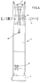
- a ladder section 2 is provided inside the building, which can also be designed as an unloading table and at the end of which a motor 6 can be connected, which is carried into the building by hand can be.
- the conductor section 2 located within the building and thus also the entire elevator 1 are fixed once by a tensioning support 12 which is tensioned between the ceiling 15 and the floor 5 and is accordingly fastened to the conductor section 2, and also by a tensioning support 14, which is oriented transversely and tensions within the window opening 4.
- a cantilever arm 40 is arranged at the front end facing away from the connection of the motor 6 of the conductor section 2 reaching inside the building, which arm - as shown in FIG. 8 - folds outwards when the elevator is being built can be and carries a pulley 48 at its end.
- a cable pulley 7 adjoins a cable pulley of the motor 6, not shown in the drawing, which acts on the material slide 8 at the other end. As a result, the material slide 8 can be moved by the motor 6 from its lower position close to the ground into the building.
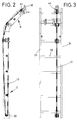
- the cable 7 is not deflected within the elevator 1, but the return force for the material slide 8 located inside the building is achieved by a return cable 17 according to FIGS. 2 and 3.
- This cable which is designed as a return cable 17, is fastened within the conductor section 2 in the region of the deflection bend 11 and is guided upwards via a corresponding deflection roller 32 and has a catch eye 18 at its upper free end, which is connected to a catch hook not shown in the drawing Material carriage 8 cooperates when the eye 18 overflows. Through this crest of the eyelet 18 with the catch hook arranged on the material carriage 8, the actual return cable 17 is tensioned when the material carriage 8 continues into the building.
- the material sled 8 When unloading inside the building, the material sled 8 is fixed accordingly and can then be moved outward via the return cable 17 when the brake is released, via the deflection bend 11, in which case it then moves the remaining part of the elevator 1 downwards due to gravity under tension of the cable pull 7 goes down.
- a cable can be used, which with a spring, for. B. a coil spring works.
- FIG. 6 and 7 show the actual material slide 8 on a somewhat larger scale.
- This consists of a base frame 33, on which two roller guides 22 and 23 are arranged, each roller guide consisting of two roller guide sets 27 and 28.
- Each roller guide set 27, 28 in turn consists of a lower roller 29 and two upper rollers 30 and 31, which lie on the one hand on the underside of the conductor struts 25 and 24 or on the top of the conductor struts 25 and 24.
- a loading platform 19, which carries two material stops 20 and 21, is mounted on the base frame 33 such that it can pivot about an articulation axis 34. These material stops 20 and 21 ensure in both directions of inclination that the goods arranged on the loading platform cannot slip off. In the inclined position, the loading platform 19 can be adjusted by means of a locking bar 35, it also being possible, of course, to set various intermediate positions between the position shown in FIG. 6 and the horizontal position.
- the elevator according to the invention can be easily assembled by craftsmen and after the conductor section 2 reaching into the building and the motor 6 have been inserted and assembled into the building by hand. Furthermore, the device according to the invention makes it possible to arrange the elevator easily and very close to the building wall 3 and to transport material into a building, wherein the inclined position of the material slide according to FIG. 6 enables the entire frame to be transported through the window opening 4.
- the clamping supports 12 and 14 arranged in the area of the building ensure sufficient Strength of the overall arrangement and the individual components are so light that the construction of the elevator by one or two people is easily possible.
- the individual parts of the elevator are still easy to transport, so that it is no longer necessary to attach a separate trailer unit to a vehicle. This is particularly important for craftsmen and urban areas.
Landscapes
- Engineering & Computer Science (AREA)
- Structural Engineering (AREA)
- Civil Engineering (AREA)
- Transportation (AREA)
- Automation & Control Theory (AREA)
- Types And Forms Of Lifts (AREA)
- Ladders (AREA)
- Forklifts And Lifting Vehicles (AREA)
- Lift-Guide Devices, And Elevator Ropes And Cables (AREA)
Applications Claiming Priority (4)
| Application Number | Priority Date | Filing Date | Title |
|---|---|---|---|
| DE4444528 | 1994-11-30 | ||
| DE4444528 | 1994-11-30 | ||
| DE19500232 | 1995-01-05 | ||
| DE19500232A DE19500232A1 (de) | 1994-11-30 | 1995-01-05 | Aufzug für in ein Gebäude oder aus einem Gebäude zu fördernde Lasten |
Publications (3)
| Publication Number | Publication Date |
|---|---|
| EP0714848A2 true EP0714848A2 (fr) | 1996-06-05 |
| EP0714848A3 EP0714848A3 (fr) | 1996-08-14 |
| EP0714848B1 EP0714848B1 (fr) | 2000-01-12 |
Family
ID=25942846
Family Applications (1)
| Application Number | Title | Priority Date | Filing Date |
|---|---|---|---|
| EP95116385A Expired - Lifetime EP0714848B1 (fr) | 1994-11-30 | 1995-10-18 | Ascenseur pour le levage de charges dans ou sur un bâtiment |
Country Status (3)
| Country | Link |
|---|---|
| EP (1) | EP0714848B1 (fr) |
| AT (1) | ATE188671T1 (fr) |
| DE (2) | DE19542774C2 (fr) |
Cited By (1)
| Publication number | Priority date | Publication date | Assignee | Title |
|---|---|---|---|---|
| CN109577657A (zh) * | 2018-11-21 | 2019-04-05 | 邹东华 | 一种砌墙用砖块输送架 |
Families Citing this family (1)
| Publication number | Priority date | Publication date | Assignee | Title |
|---|---|---|---|---|
| DE102008003295A1 (de) | 2008-01-05 | 2009-07-09 | Khs Ag | Behälterzelle, insbesondere Flaschenzelle, Behälterkorb mit derartigen Behälterzellen sowie Verfahren zum Herstellen von Behälterzellen |
Citations (2)
| Publication number | Priority date | Publication date | Assignee | Title |
|---|---|---|---|---|
| GB1378318A (en) | 1973-03-15 | 1974-12-27 | Evans P N | Material hoists |
| FR2547568A1 (fr) | 1983-06-14 | 1984-12-21 | Haemmerlin Georges Sa | Monte-materiaux a equipage mobile deplacable verticalement et horizontalement |
Family Cites Families (5)
| Publication number | Priority date | Publication date | Assignee | Title |
|---|---|---|---|---|
| US1430655A (en) * | 1921-09-17 | 1922-10-03 | William F Irrgang | Hoisting mechanism |
| DE1854167U (de) * | 1962-04-10 | 1962-06-28 | Theodor Klaas | Materialaufzug zum gebrauch fuer dachdecker. |
| CA1172198A (fr) * | 1982-02-11 | 1984-08-07 | Donald Gagnon | Palan porte par une echelle |
| US4793437A (en) * | 1987-07-20 | 1988-12-27 | Philip Hanthorn | Portable lift with telescopic booms and load-carrying apparatus |
| DE3816106C2 (de) * | 1988-05-11 | 1997-04-10 | Boecker Albert Gmbh & Co Kg | Mehrfachscharniergelenk zur Verbindung der Schienenabschnitte einer abknickbaren Führungsschiene eines Schrägaufzuges |
-
1995
- 1995-01-05 DE DE19542774A patent/DE19542774C2/de not_active Expired - Fee Related
- 1995-01-05 DE DE19542773A patent/DE19542773C2/de not_active Expired - Fee Related
- 1995-10-18 EP EP95116385A patent/EP0714848B1/fr not_active Expired - Lifetime
- 1995-10-18 AT AT95116385T patent/ATE188671T1/de not_active IP Right Cessation
Patent Citations (2)
| Publication number | Priority date | Publication date | Assignee | Title |
|---|---|---|---|---|
| GB1378318A (en) | 1973-03-15 | 1974-12-27 | Evans P N | Material hoists |
| FR2547568A1 (fr) | 1983-06-14 | 1984-12-21 | Haemmerlin Georges Sa | Monte-materiaux a equipage mobile deplacable verticalement et horizontalement |
Cited By (1)
| Publication number | Priority date | Publication date | Assignee | Title |
|---|---|---|---|---|
| CN109577657A (zh) * | 2018-11-21 | 2019-04-05 | 邹东华 | 一种砌墙用砖块输送架 |
Also Published As
| Publication number | Publication date |
|---|---|
| DE19542773C2 (de) | 1998-04-16 |
| EP0714848A3 (fr) | 1996-08-14 |
| EP0714848B1 (fr) | 2000-01-12 |
| ATE188671T1 (de) | 2000-01-15 |
| DE19542773A1 (de) | 1996-06-05 |
| DE19542774A1 (de) | 1996-06-05 |
| DE19542774C2 (de) | 1998-04-16 |
Similar Documents
| Publication | Publication Date | Title |
|---|---|---|
| DE8911634U1 (de) | In Teilen transportierbares Vergnügungsgerät für Jahrmärkte od.dgl., insbesondere Riesenrad | |
| DE2646662A1 (de) | Zusammenlegbare auffahr- und montagerampe | |
| EP0612886A1 (fr) | Pont déplaçable et dispositif pour la pose du pont | |
| DE3911868C2 (fr) | ||
| EP0714848B1 (fr) | Ascenseur pour le levage de charges dans ou sur un bâtiment | |
| DE10025074B4 (de) | Einrichtung zum Befördern von Personen | |
| DE3330082C2 (de) | Bausatz für einen Schrägaufzug | |
| DE10114359A1 (de) | Mobile Fördereinrichtung mit Verteilermast und begehbaren Pritschen | |
| DE19500232A1 (de) | Aufzug für in ein Gebäude oder aus einem Gebäude zu fördernde Lasten | |
| DE3015720A1 (de) | Einsteighilfe fuer die fahrerkabine eines einschienenhaengebahnzugs | |
| DE3443000C1 (de) | Parkeinrichtung fuer Kraftfahrzeuge | |
| EP1508472B1 (fr) | Véhicule avec un écran déployable | |
| DE3222697C2 (de) | Mobiler Schienenaufzug mit neigungsverstellbarer Teleskopschiene | |
| DE3433537A1 (de) | Turmdrehkran | |
| DE69300244T2 (de) | Hubladeeinrichtung zur Anwendung an einem Lastwagenbehälter. | |
| DE9201136U1 (de) | Gerät mit einer in ihrer Höhe verstellbaren Arbeitsbühne | |
| EP0383987B1 (fr) | Dispositif d'entraînement pour ponts de transbordement pour rampes | |
| DE19540426A1 (de) | Ladeplattform für ein Transportfahrzeug | |
| DE9011328U1 (de) | Gebäudekran | |
| DE2003440B2 (de) | Schiffsfallreep | |
| DE1481792A1 (de) | Kran,insbesondere Baukran | |
| DE2556891B2 (de) | Fahrbare, mit einem schutzgelaender versehene arbeitsbuehne, auf der ein hebezeug fuer montageteile montiert ist | |
| DE8622268U1 (de) | Mobiler Lastaufzug | |
| DE9316850U1 (de) | Rettungsvorrichtung | |
| DE19829220A1 (de) | An einer Stütze montierbarer Kran |
Legal Events
| Date | Code | Title | Description |
|---|---|---|---|
| PUAI | Public reference made under article 153(3) epc to a published international application that has entered the european phase |
Free format text: ORIGINAL CODE: 0009012 |
|
| AK | Designated contracting states |
Kind code of ref document: A2 Designated state(s): AT CH DE ES FR GB IT LI |
|
| PUAL | Search report despatched |
Free format text: ORIGINAL CODE: 0009013 |
|
| AK | Designated contracting states |
Kind code of ref document: A3 Designated state(s): AT CH DE ES FR GB IT LI |
|
| 17P | Request for examination filed |
Effective date: 19960717 |
|
| 17Q | First examination report despatched |
Effective date: 19981127 |
|
| GRAG | Despatch of communication of intention to grant |
Free format text: ORIGINAL CODE: EPIDOS AGRA |
|
| RAP3 | Party data changed (applicant data changed or rights of an application transferred) |
Owner name: FIRMA KAETHE SCHULTEN |
|
| GRAG | Despatch of communication of intention to grant |
Free format text: ORIGINAL CODE: EPIDOS AGRA |
|
| GRAH | Despatch of communication of intention to grant a patent |
Free format text: ORIGINAL CODE: EPIDOS IGRA |
|
| GRAH | Despatch of communication of intention to grant a patent |
Free format text: ORIGINAL CODE: EPIDOS IGRA |
|
| GRAA | (expected) grant |
Free format text: ORIGINAL CODE: 0009210 |
|
| AK | Designated contracting states |
Kind code of ref document: B1 Designated state(s): AT CH DE ES FR GB IT LI |
|
| PG25 | Lapsed in a contracting state [announced via postgrant information from national office to epo] |
Ref country code: IT Free format text: LAPSE BECAUSE OF FAILURE TO SUBMIT A TRANSLATION OF THE DESCRIPTION OR TO PAY THE FEE WITHIN THE PRE;WARNING: LAPSES OF ITALIAN PATENTS WITH EFFECTIVE DATE BEFORE 2007 MAY HAVE OCCURRED AT ANY TIME BEFORE 2007. THE CORRECT EFFECTIVE DATE MAY BE DIFFERENT FROM THE ONE RECORDED.SCRIBED TIME-LIMIT Effective date: 20000112 Ref country code: GB Free format text: LAPSE BECAUSE OF FAILURE TO SUBMIT A TRANSLATION OF THE DESCRIPTION OR TO PAY THE FEE WITHIN THE PRESCRIBED TIME-LIMIT Effective date: 20000112 Ref country code: FR Free format text: LAPSE BECAUSE OF FAILURE TO SUBMIT A TRANSLATION OF THE DESCRIPTION OR TO PAY THE FEE WITHIN THE PRESCRIBED TIME-LIMIT Effective date: 20000112 Ref country code: ES Free format text: THE PATENT HAS BEEN ANNULLED BY A DECISION OF A NATIONAL AUTHORITY Effective date: 20000112 |
|
| REF | Corresponds to: |
Ref document number: 188671 Country of ref document: AT Date of ref document: 20000115 Kind code of ref document: T |
|
| REG | Reference to a national code |
Ref country code: CH Ref legal event code: EP |
|
| REF | Corresponds to: |
Ref document number: 59507609 Country of ref document: DE Date of ref document: 20000217 |
|
| EN | Fr: translation not filed | ||
| GBV | Gb: ep patent (uk) treated as always having been void in accordance with gb section 77(7)/1977 [no translation filed] |
Effective date: 20000112 |
|
| PG25 | Lapsed in a contracting state [announced via postgrant information from national office to epo] |
Ref country code: AT Free format text: LAPSE BECAUSE OF NON-PAYMENT OF DUE FEES Effective date: 20001018 |
|
| PG25 | Lapsed in a contracting state [announced via postgrant information from national office to epo] |
Ref country code: LI Free format text: LAPSE BECAUSE OF NON-PAYMENT OF DUE FEES Effective date: 20001031 Ref country code: CH Free format text: LAPSE BECAUSE OF NON-PAYMENT OF DUE FEES Effective date: 20001031 |
|
| PLBE | No opposition filed within time limit |
Free format text: ORIGINAL CODE: 0009261 |
|
| STAA | Information on the status of an ep patent application or granted ep patent |
Free format text: STATUS: NO OPPOSITION FILED WITHIN TIME LIMIT |
|
| 26N | No opposition filed | ||
| REG | Reference to a national code |
Ref country code: CH Ref legal event code: PL |
|
| PGFP | Annual fee paid to national office [announced via postgrant information from national office to epo] |
Ref country code: DE Payment date: 20011024 Year of fee payment: 7 |
|
| PG25 | Lapsed in a contracting state [announced via postgrant information from national office to epo] |
Ref country code: DE Free format text: LAPSE BECAUSE OF NON-PAYMENT OF DUE FEES Effective date: 20030501 |