EP0714918A2 - Procédé pour séparer des polymères de mélanges de ceux-ci - Google Patents
Procédé pour séparer des polymères de mélanges de ceux-ci Download PDFInfo
- Publication number
- EP0714918A2 EP0714918A2 EP95117369A EP95117369A EP0714918A2 EP 0714918 A2 EP0714918 A2 EP 0714918A2 EP 95117369 A EP95117369 A EP 95117369A EP 95117369 A EP95117369 A EP 95117369A EP 0714918 A2 EP0714918 A2 EP 0714918A2
- Authority
- EP
- European Patent Office
- Prior art keywords
- shear
- melt viscosity
- thermoplastic polymer
- polymer
- phase
- Prior art date
- Legal status (The legal status is an assumption and is not a legal conclusion. Google has not performed a legal analysis and makes no representation as to the accuracy of the status listed.)
- Granted
Links
- 239000000203 mixture Substances 0.000 title claims abstract description 108
- 238000000034 method Methods 0.000 title claims abstract description 79
- 229920000642 polymer Polymers 0.000 title description 151
- 229920001169 thermoplastic Polymers 0.000 claims abstract description 56
- 239000007788 liquid Substances 0.000 claims abstract description 29
- 238000004064 recycling Methods 0.000 claims abstract description 26
- 239000000835 fiber Substances 0.000 claims description 34
- 238000009987 spinning Methods 0.000 claims description 16
- 238000009826 distribution Methods 0.000 claims description 9
- 239000004952 Polyamide Substances 0.000 claims description 8
- 229920002647 polyamide Polymers 0.000 claims description 8
- 229920000728 polyester Polymers 0.000 claims description 7
- 229920000098 polyolefin Polymers 0.000 claims description 7
- 238000011144 upstream manufacturing Methods 0.000 claims description 3
- 238000000926 separation method Methods 0.000 abstract description 44
- 229920002959 polymer blend Polymers 0.000 abstract description 36
- 229920001903 high density polyethylene Polymers 0.000 description 17
- 239000004700 high-density polyethylene Substances 0.000 description 17
- 239000004677 Nylon Substances 0.000 description 11
- 229920001778 nylon Polymers 0.000 description 11
- 230000008569 process Effects 0.000 description 11
- 230000007246 mechanism Effects 0.000 description 10
- 229920000139 polyethylene terephthalate Polymers 0.000 description 10
- 239000005020 polyethylene terephthalate Substances 0.000 description 10
- 229920002292 Nylon 6 Polymers 0.000 description 9
- 239000002699 waste material Substances 0.000 description 9
- 230000007423 decrease Effects 0.000 description 7
- 239000000155 melt Substances 0.000 description 7
- 229920003023 plastic Polymers 0.000 description 7
- 239000004033 plastic Substances 0.000 description 7
- 239000007787 solid Substances 0.000 description 7
- 238000001125 extrusion Methods 0.000 description 6
- 239000006185 dispersion Substances 0.000 description 5
- 230000003287 optical effect Effects 0.000 description 5
- 230000008901 benefit Effects 0.000 description 4
- 238000001514 detection method Methods 0.000 description 4
- -1 e.g. Substances 0.000 description 4
- 239000002245 particle Substances 0.000 description 4
- 238000010008 shearing Methods 0.000 description 4
- 239000004698 Polyethylene Substances 0.000 description 3
- 239000004743 Polypropylene Substances 0.000 description 3
- 239000000463 material Substances 0.000 description 3
- 239000011159 matrix material Substances 0.000 description 3
- 238000002844 melting Methods 0.000 description 3
- 230000008018 melting Effects 0.000 description 3
- 239000003960 organic solvent Substances 0.000 description 3
- 229920000573 polyethylene Polymers 0.000 description 3
- 229920001155 polypropylene Polymers 0.000 description 3
- 239000000126 substance Substances 0.000 description 3
- 239000004416 thermosoftening plastic Substances 0.000 description 3
- 238000004891 communication Methods 0.000 description 2
- 230000007613 environmental effect Effects 0.000 description 2
- 238000000227 grinding Methods 0.000 description 2
- 239000000383 hazardous chemical Substances 0.000 description 2
- 238000004519 manufacturing process Methods 0.000 description 2
- 239000002184 metal Substances 0.000 description 2
- 238000002156 mixing Methods 0.000 description 2
- 230000004048 modification Effects 0.000 description 2
- 238000012986 modification Methods 0.000 description 2
- 238000012545 processing Methods 0.000 description 2
- 239000000047 product Substances 0.000 description 2
- 239000011347 resin Substances 0.000 description 2
- 229920005989 resin Polymers 0.000 description 2
- 238000000518 rheometry Methods 0.000 description 2
- 239000002904 solvent Substances 0.000 description 2
- 229920001410 Microfiber Polymers 0.000 description 1
- 230000009471 action Effects 0.000 description 1
- 230000002411 adverse Effects 0.000 description 1
- 238000013459 approach Methods 0.000 description 1
- 230000033228 biological regulation Effects 0.000 description 1
- 230000015572 biosynthetic process Effects 0.000 description 1
- 238000005520 cutting process Methods 0.000 description 1
- 238000011161 development Methods 0.000 description 1
- 230000000694 effects Effects 0.000 description 1
- 238000005516 engineering process Methods 0.000 description 1
- 238000002474 experimental method Methods 0.000 description 1
- 239000004744 fabric Substances 0.000 description 1
- 238000001914 filtration Methods 0.000 description 1
- 239000012467 final product Substances 0.000 description 1
- 239000012530 fluid Substances 0.000 description 1
- 239000011521 glass Substances 0.000 description 1
- 231100000206 health hazard Toxicity 0.000 description 1
- 239000008241 heterogeneous mixture Substances 0.000 description 1
- 229920005621 immiscible polymer blend Polymers 0.000 description 1
- 238000002329 infrared spectrum Methods 0.000 description 1
- 238000001746 injection moulding Methods 0.000 description 1
- 150000002500 ions Chemical class 0.000 description 1
- 239000003658 microfiber Substances 0.000 description 1
- 239000003208 petroleum Substances 0.000 description 1
- 239000003209 petroleum derivative Substances 0.000 description 1
- JTJMJGYZQZDUJJ-UHFFFAOYSA-N phencyclidine Chemical class C1CCCCN1C1(C=2C=CC=CC=2)CCCCC1 JTJMJGYZQZDUJJ-UHFFFAOYSA-N 0.000 description 1
- 239000013502 plastic waste Substances 0.000 description 1
- 238000000197 pyrolysis Methods 0.000 description 1
- 238000003908 quality control method Methods 0.000 description 1
- 239000002994 raw material Substances 0.000 description 1
- 239000004576 sand Substances 0.000 description 1
- 239000000243 solution Substances 0.000 description 1
- 238000013316 zoning Methods 0.000 description 1
Images


Classifications
-
- D—TEXTILES; PAPER
- D01—NATURAL OR MAN-MADE THREADS OR FIBRES; SPINNING
- D01D—MECHANICAL METHODS OR APPARATUS IN THE MANUFACTURE OF ARTIFICIAL FILAMENTS, THREADS, FIBRES, BRISTLES OR RIBBONS
- D01D5/00—Formation of filaments, threads, or the like
- D01D5/28—Formation of filaments, threads, or the like while mixing different spinning solutions or melts during the spinning operation; Spinnerette packs therefor
- D01D5/30—Conjugate filaments; Spinnerette packs therefor
- D01D5/34—Core-skin structure; Spinnerette packs therefor
-
- B—PERFORMING OPERATIONS; TRANSPORTING
- B29—WORKING OF PLASTICS; WORKING OF SUBSTANCES IN A PLASTIC STATE IN GENERAL
- B29B—PREPARATION OR PRETREATMENT OF THE MATERIAL TO BE SHAPED; MAKING GRANULES OR PREFORMS; RECOVERY OF PLASTICS OR OTHER CONSTITUENTS OF WASTE MATERIAL CONTAINING PLASTICS
- B29B13/00—Conditioning or physical treatment of the material to be shaped
- B29B13/02—Conditioning or physical treatment of the material to be shaped by heating
- B29B13/022—Melting the material to be shaped
-
- B—PERFORMING OPERATIONS; TRANSPORTING
- B29—WORKING OF PLASTICS; WORKING OF SUBSTANCES IN A PLASTIC STATE IN GENERAL
- B29B—PREPARATION OR PRETREATMENT OF THE MATERIAL TO BE SHAPED; MAKING GRANULES OR PREFORMS; RECOVERY OF PLASTICS OR OTHER CONSTITUENTS OF WASTE MATERIAL CONTAINING PLASTICS
- B29B17/00—Recovery of plastics or other constituents of waste material containing plastics
- B29B17/02—Separating plastics from other materials
-
- B—PERFORMING OPERATIONS; TRANSPORTING
- B29—WORKING OF PLASTICS; WORKING OF SUBSTANCES IN A PLASTIC STATE IN GENERAL
- B29C—SHAPING OR JOINING OF PLASTICS; SHAPING OF MATERIAL IN A PLASTIC STATE, NOT OTHERWISE PROVIDED FOR; AFTER-TREATMENT OF THE SHAPED PRODUCTS, e.g. REPAIRING
- B29C48/00—Extrusion moulding, i.e. expressing the moulding material through a die or nozzle which imparts the desired form; Apparatus therefor
- B29C48/03—Extrusion moulding, i.e. expressing the moulding material through a die or nozzle which imparts the desired form; Apparatus therefor characterised by the shape of the extruded material at extrusion
- B29C48/05—Filamentary, e.g. strands
-
- B—PERFORMING OPERATIONS; TRANSPORTING
- B29—WORKING OF PLASTICS; WORKING OF SUBSTANCES IN A PLASTIC STATE IN GENERAL
- B29C—SHAPING OR JOINING OF PLASTICS; SHAPING OF MATERIAL IN A PLASTIC STATE, NOT OTHERWISE PROVIDED FOR; AFTER-TREATMENT OF THE SHAPED PRODUCTS, e.g. REPAIRING
- B29C48/00—Extrusion moulding, i.e. expressing the moulding material through a die or nozzle which imparts the desired form; Apparatus therefor
- B29C48/03—Extrusion moulding, i.e. expressing the moulding material through a die or nozzle which imparts the desired form; Apparatus therefor characterised by the shape of the extruded material at extrusion
- B29C48/06—Rod-shaped
-
- B—PERFORMING OPERATIONS; TRANSPORTING
- B29—WORKING OF PLASTICS; WORKING OF SUBSTANCES IN A PLASTIC STATE IN GENERAL
- B29C—SHAPING OR JOINING OF PLASTICS; SHAPING OF MATERIAL IN A PLASTIC STATE, NOT OTHERWISE PROVIDED FOR; AFTER-TREATMENT OF THE SHAPED PRODUCTS, e.g. REPAIRING
- B29C48/00—Extrusion moulding, i.e. expressing the moulding material through a die or nozzle which imparts the desired form; Apparatus therefor
- B29C48/03—Extrusion moulding, i.e. expressing the moulding material through a die or nozzle which imparts the desired form; Apparatus therefor characterised by the shape of the extruded material at extrusion
- B29C48/09—Articles with cross-sections having partially or fully enclosed cavities, e.g. pipes or channels
-
- B—PERFORMING OPERATIONS; TRANSPORTING
- B29—WORKING OF PLASTICS; WORKING OF SUBSTANCES IN A PLASTIC STATE IN GENERAL
- B29C—SHAPING OR JOINING OF PLASTICS; SHAPING OF MATERIAL IN A PLASTIC STATE, NOT OTHERWISE PROVIDED FOR; AFTER-TREATMENT OF THE SHAPED PRODUCTS, e.g. REPAIRING
- B29C48/00—Extrusion moulding, i.e. expressing the moulding material through a die or nozzle which imparts the desired form; Apparatus therefor
- B29C48/16—Articles comprising two or more components, e.g. co-extruded layers
- B29C48/18—Articles comprising two or more components, e.g. co-extruded layers the components being layers
- B29C48/21—Articles comprising two or more components, e.g. co-extruded layers the components being layers the layers being joined at their surfaces
-
- B—PERFORMING OPERATIONS; TRANSPORTING
- B29—WORKING OF PLASTICS; WORKING OF SUBSTANCES IN A PLASTIC STATE IN GENERAL
- B29C—SHAPING OR JOINING OF PLASTICS; SHAPING OF MATERIAL IN A PLASTIC STATE, NOT OTHERWISE PROVIDED FOR; AFTER-TREATMENT OF THE SHAPED PRODUCTS, e.g. REPAIRING
- B29C48/00—Extrusion moulding, i.e. expressing the moulding material through a die or nozzle which imparts the desired form; Apparatus therefor
- B29C48/25—Component parts, details or accessories; Auxiliary operations
- B29C48/30—Extrusion nozzles or dies
- B29C48/304—Extrusion nozzles or dies specially adapted for bringing together components, e.g. melts within the die
-
- B—PERFORMING OPERATIONS; TRANSPORTING
- B29—WORKING OF PLASTICS; WORKING OF SUBSTANCES IN A PLASTIC STATE IN GENERAL
- B29C—SHAPING OR JOINING OF PLASTICS; SHAPING OF MATERIAL IN A PLASTIC STATE, NOT OTHERWISE PROVIDED FOR; AFTER-TREATMENT OF THE SHAPED PRODUCTS, e.g. REPAIRING
- B29C48/00—Extrusion moulding, i.e. expressing the moulding material through a die or nozzle which imparts the desired form; Apparatus therefor
- B29C48/25—Component parts, details or accessories; Auxiliary operations
- B29C48/30—Extrusion nozzles or dies
- B29C48/32—Extrusion nozzles or dies with annular openings, e.g. for forming tubular articles
- B29C48/335—Multiple annular extrusion nozzles in coaxial arrangement, e.g. for making multi-layered tubular articles
-
- C—CHEMISTRY; METALLURGY
- C08—ORGANIC MACROMOLECULAR COMPOUNDS; THEIR PREPARATION OR CHEMICAL WORKING-UP; COMPOSITIONS BASED THEREON
- C08F—MACROMOLECULAR COMPOUNDS OBTAINED BY REACTIONS ONLY INVOLVING CARBON-TO-CARBON UNSATURATED BONDS
- C08F6/00—Post-polymerisation treatments
- C08F6/04—Fractionation
-
- B—PERFORMING OPERATIONS; TRANSPORTING
- B29—WORKING OF PLASTICS; WORKING OF SUBSTANCES IN A PLASTIC STATE IN GENERAL
- B29B—PREPARATION OR PRETREATMENT OF THE MATERIAL TO BE SHAPED; MAKING GRANULES OR PREFORMS; RECOVERY OF PLASTICS OR OTHER CONSTITUENTS OF WASTE MATERIAL CONTAINING PLASTICS
- B29B17/00—Recovery of plastics or other constituents of waste material containing plastics
- B29B17/02—Separating plastics from other materials
- B29B2017/0203—Separating plastics from plastics
-
- B—PERFORMING OPERATIONS; TRANSPORTING
- B29—WORKING OF PLASTICS; WORKING OF SUBSTANCES IN A PLASTIC STATE IN GENERAL
- B29K—INDEXING SCHEME ASSOCIATED WITH SUBCLASSES B29B, B29C OR B29D, RELATING TO MOULDING MATERIALS OR TO MATERIALS FOR MOULDS, REINFORCEMENTS, FILLERS OR PREFORMED PARTS, e.g. INSERTS
- B29K2023/00—Use of polyalkenes or derivatives thereof as moulding material
- B29K2023/04—Polymers of ethylene
- B29K2023/06—PE, i.e. polyethylene
-
- B—PERFORMING OPERATIONS; TRANSPORTING
- B29—WORKING OF PLASTICS; WORKING OF SUBSTANCES IN A PLASTIC STATE IN GENERAL
- B29K—INDEXING SCHEME ASSOCIATED WITH SUBCLASSES B29B, B29C OR B29D, RELATING TO MOULDING MATERIALS OR TO MATERIALS FOR MOULDS, REINFORCEMENTS, FILLERS OR PREFORMED PARTS, e.g. INSERTS
- B29K2077/00—Use of PA, i.e. polyamides, e.g. polyesteramides or derivatives thereof, as moulding material
-
- B—PERFORMING OPERATIONS; TRANSPORTING
- B29—WORKING OF PLASTICS; WORKING OF SUBSTANCES IN A PLASTIC STATE IN GENERAL
- B29K—INDEXING SCHEME ASSOCIATED WITH SUBCLASSES B29B, B29C OR B29D, RELATING TO MOULDING MATERIALS OR TO MATERIALS FOR MOULDS, REINFORCEMENTS, FILLERS OR PREFORMED PARTS, e.g. INSERTS
- B29K2105/00—Condition, form or state of moulded material or of the material to be shaped
- B29K2105/06—Condition, form or state of moulded material or of the material to be shaped containing reinforcements, fillers or inserts
-
- Y—GENERAL TAGGING OF NEW TECHNOLOGICAL DEVELOPMENTS; GENERAL TAGGING OF CROSS-SECTIONAL TECHNOLOGIES SPANNING OVER SEVERAL SECTIONS OF THE IPC; TECHNICAL SUBJECTS COVERED BY FORMER USPC CROSS-REFERENCE ART COLLECTIONS [XRACs] AND DIGESTS
- Y02—TECHNOLOGIES OR APPLICATIONS FOR MITIGATION OR ADAPTATION AGAINST CLIMATE CHANGE
- Y02W—CLIMATE CHANGE MITIGATION TECHNOLOGIES RELATED TO WASTEWATER TREATMENT OR WASTE MANAGEMENT
- Y02W30/00—Technologies for solid waste management
- Y02W30/50—Reuse, recycling or recovery technologies
- Y02W30/62—Plastics recycling; Rubber recycling
Definitions
- This invention relates to a method of separating immiscible polymers from mixtures thereof. More particularly, this invention relates to a method of separating immiscible polymers from mixtures thereof based on melt viscosity differences between the polymers,and further to the use of said method in recycling mixed polymer waste.
- Recycling waste into useful materials is a growing goal in modern society, particularly in the plastics and fibers industries. Landfills are becoming filled to capacity and new sites are hard to find because of zoning regulations and neighborhood concerns. Recycling waste is also important because of the growing global depletion of raw materials needed to make fresh material.
- Polymer waste often made from petroleum products, is a fertile area for recycling. Man-made polymers generally do not degrade quickly and petroleum will eventually be depleted. Thus far, mixed polymer waste, particularly mixed polymer waste containing immiscible polymers, have posed unique recycling problems. For example, while nylon and PET individually can be readily recycled, mixtures of nylon and PET are not easily recycled as even blends of virgin nylon and PET blends do not readily spin into yarn.
- Immiscible polymer blends such as most nylon 6/PET blends, exhibit multiple melting points and form liquid dispersions which appear as a heterogenous mixture when viewed under a microscope. Such immiscible mixtures often have poor adhesion between the phases.
- the morphology of these dispersions can present certain challenges in forming the mixture into articles such as fibers as the morphology adversely affects the spinning and drawing processes.
- some dispersions e.g., nylon/PET liquid dispersions, display a morphology where one polymer forms globules that are surrounded by the other polymer. The size and shape of these globules affect the properties of the final yarn.
- the globules must be significantly smaller than the spinneret capillary diameter for the mixture to flow in a nearly homogenous manner.
- the spun fiber will contain long fibrils that deform along with the matrix polymer.
- the blend will contain large globules that are rigid during drawing.
- Recycling the individual polymers in a polymer mixture would involve separating the polymers from the mixture.
- Current polymer separation processes usually involve mechanical separation, chemical separation or a mixture of these approaches. However, these processes are difficult and expensive to operate.
- An object of this invention is to provide a less expensive method of separating immiscible polymers from a mixture thereof.
- Another object of this invention is to provide a method of separating immiscible polymers from a mixture thereof wherein separation does not require the use of significant amounts of organic solvent.
- a further object of this invention is to use the separation method described in the foregoing objects to recycle mixed polymers.
- a still further object of this invention is to provide a method of recycling immiscible polymer mixtures which takes advantage of the ease associated with recycling individual polymers.
- Another object of this invention is to provide a method of making bicomponent articles, such as sheath/core bicomponent fibers, which requires the use of only one extruder.
- the present invention is based in part on the discovery that immiscible polymers can be separated from mixtures thereof by means of their melt viscosity differences.
- This invention is also based in part on the discovery that the above polymer separation method can be used in recycling mixed polymer waste.
- This invention is also based on the surprising discovery that factors which previously have been considered obstacles to recycling polymer mixtures, e.g., heterogenous polymer dispersions and poor adhesion between the polymer phases, can actually facilitate the substantial separation of the polymers and the recycling of polymer mixtures under proper conditions.
- one aspect of this invention is directed to a method of separating at least two immiscible thermoplastic polymer components from a liquid mixture thereof, wherein a first of said at least two immiscible thermoplastic polymer components has a first melt viscosity and a second of said at least two immiscible thermoplastic polymer components has a second melt viscosity, wherein said second melt viscosity is higher than said first melt viscosity, wherein said method comprises flowing said liquid mixture through a shear zone, wherein said liquid mixture is subjected to shear in said shear zone at a shear rate and a shear temperature sufficient to separate said at least two immiscible thermoplastic polymer components into substantially discrete and continuous phases, wherein a first of said phases substantially comprises the thermoplastic polymer component having the first melt viscosity and a second of said phases substantially comprises the thermoplastic polymer component having the second melt viscosity.
- a second aspect of the present invention is directed to a method of recycling a liquid polymer mixture comprising at least two immiscible thermoplastic polymers with different melt viscosity values, comprising subjecting the mixture to the separation method described above and forming articles from either the individual polymers or separated mixture thereof.
- a method of recycling polymer mixtures that involves separating polymers from mixtures thereof as described above has the added advantage of imparting uniformity to the final product.
- the method of this invention also provides the advantage of requiring only one extruder to form bicomponent articles, such as bicomponent sheath/core fibers.
- Two or more immiscible polymers are fed into a single extruder to form a mixture, and the resulting mixture is passed through the shear zone. Mechanical separation of the polymers is not required because the polymers are spun directly from the shear zone.
- Another benefit provided by the method of this invention is that it allows for the use of a single extruder in a process wherein two or more immiscible polymers are mixed, separated and then recombined to form an article, e.g., a fiber, with a desirable cross-section.
- FIG. 1 is a schematic illustration showing a useful shear zone in the form of a capillary used in the present invention.
- FIG. 2 represents a perspective, cut-away view of the capillary represented in FIG. 1 showing a means useful to separate the individual polymers from each other.
- FIGS. 3-5 represent cross-sections of a two-polymer mixture at various stages of the shearing process in the capillary represented in FIG. 1.
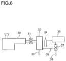
- FIG. 6 is a schematic representation of the devices used in the method of the present invention, including a polymer separation detection device and a second polymer metering pump.
- FIG. 7 is a schematic representation of an optical microscopic photograph taken of the cross- section of a monofilament sample prepared according to the method of this invention, wherein FIG. 7 shows separation into a sheath/core structure.
- FIG. 8 is a schematic representation of an optical microscopic photograph taken of the cross- section of a monofilament sample prepared according to the method of this invention, wherein FIG. 8 shows failure of separation, resulting in a mixed structure.
- FIG. 9 is a schematic representation of an optical microscopic photograph taken of the croSS- sect ion of a monofilament sample prepared according to the method of this invention, wherein FIG. 9 shows separation into a ring structure.
- FIG. 10 is a schematic representation of an optical microscopic photograph taken of the cross-section of a monofilament sample prepared according to the method of this invention, wherein FIG. 10 shows separation into a partial sheath/core structure and a partial side-by-side structure.
- At least two immiscible thermoplastic polymer components having different melt viscosity values are separated from a liquid mixture thereof.
- immiscible as used herein means that the polymer components are insoluble or substantially insoluble with one another.
- polymer component as used herein refers to one or more polymers of the same class having similar melt viscosities.
- the liquid mixture is passed through a shear zone at a shear rate and a shear temperature sufficient to separate the polymer components having different melt viscosity values into substantially discrete and continuous phases.
- the formation of the phases is the result of the shearing action, which generally causes one polymer component to move away from the central region of the shear zone and the other polymer component to move toward the central region of the shear zone.
- the shear temperature and the shear rate are sufficient to separate the immiscible thermoplastic polymer components into a sheath/core configuration having a core phase and a sheath phase, the sheath phase surrounding the core phase.
- the core phase substantially contains the thermoplastic polymer component having the second melt viscosity
- the sheath phase substantially contains the thermoplastic polymer component having the first melt viscosity.
- Exiting the shear zone are two or more output streams each substantially containing one of the discrete phases or a single output stream containing substantially uniform separated phases.
- substantially uniform as used herein is meant to convey that each polymer in the mixture is contained in a separate continuous phase as opposed to a plurality of discrete islands in a matrix.
- the liquid mixture subjected to shear in this invention contains two immiscible thermoplastic polymers having different melt viscosity values.
- Thermoplastic polymer mixtures which can be sheared according to the method of this invention include, for example, those polymer mixtures found in scraps resulting from fiber, yarn, fabric and plastics processing procedures, discarded consumer products, and other waste materials which are desired to be recycled.
- thermoplastic polymers suitable for separation in the method of this invention include those useful in fiber spinning processes.
- Such polymers include, for example, polyamides, polyesters, and polyolefins.
- Non-limiting examples of polymer mixtures which can be separated include, e.g., polyamide/polyester mixtures, polyamide/polyolefin mixtures, and polyester/polyolefin mixtures.
- Polycaproamide/polyethylene mixtures are readily separated in the practice of the method of this invention.
- polyamide/polyethylene terephthalate such as polycaproamide/polyethylene terephthalate
- polyamide/polypropylene such as polycaproamide/polypropylene
- polyamide/polyethylene such as polyamide/high density polyethylene and polycaproamide/high density polyethylene
- polyethylene terephthalate/polyethylene and polyethylene terephthalate/polypropylene mixtures are not intended to limit the present invention as it is believed that any immiscible thermoplastic polymer mixture having
- the thermoplastic polymer component having the first melt viscosity is high density polyethylene and the thermoplastic polymer component having the second melt viscosity is polycaproamide.
- the weight ratio of each polymer component contained in the liquid mixture to be separated can vary widely from 99:1 to 1:99.
- the mixture to be separated is in a liquid state prior to passing through the shear zone.
- liquid refers to a molten state or a molten state in admixture with a small amount of solvent so as to increase the fluidity of a portion of the polymer mixture.
- the mixture is in a purely molten state with no added solvent.
- the molten mixture is prepared by means of extrusion.
- a molten polymer mixture can be prepared by feeding the mixture, typically in the form of a finely divided or granulated mixed solid, to a single screw extruder with a metering section or pump.
- the extruder can be any conventional laboratory-scale or full-scale screw extruder commonly used in processing thermoplastic polymers, e.g., in mixing, homogenizing, extruding, granulating, spinning and similar operations.
- An example of a suitable laboratory-scale extruder is an extruder having a screw diameter of one inch and depth of channel in the metering section of 0.031 inch.
- An example of a suitable full-scale extruder is one having a screw diameter of 3.5 inches and a metering section channel depth of 0.0938 inch.
- the mixture is subjected to a temperature sufficient to melt all components of the mixture (i.e., melting temperature).
- melting temperatures ranging from about 265°C to about 300°C have been found useful.
- the extruded liquid mixture is passed through a shear zone, preferably in a laminar flow. Turbulence in the flow of the mixture through the shear zone should be avoided.
- the Reynolds value (a measure of the turbulence in the flow) of the flow is preferably less than about 4000, more preferably less than about 3000, and most preferably less than about 2000.
- the inner wall of the shear zone should be smooth.
- the shear temperature preferably ranges from about 250°C to about 300°C, and more preferably from about 270°C to about 285°C.
- the shear rate preferably ranges from about 200 l/sec to about 1100 l/sec, more preferably from about 200 l/sec to about 700 l/sec, and most preferably from about 300 l/sec to about 500 l/sec.
- the immiscible thermoplastic polymers in the mixture preferably have a melt viscosity ratio of from about 2:1 to about 7:1, more preferably from about 2:1 to about 3:1, and most preferably from about 2.3:1 to about 2.7:1.
- the thermoplastic polymer component having the first melt viscosity is high density polyethylene and the thermoplastic polymer component having the second melt viscosity is polycaproamide
- the melt viscosity ratio of said second melt viscosity to said first melt viscosity ranges from about 2:1 to about 7:1, more preferably from about 2:1 to about 3:1, most preferably from about 2.3:1 to about 2.7:1
- the liquid mixture is in a molten state
- the shear temperature ranges from about 250°C to about 300°C, more preferably from about 270 to about 285°C
- the shear rate ranges from about 200 l/sec to about 1100 l/sec, more preferably from about 200 l/sec to about 700 l/sec, and most preferably from about 300 l/sec to about 500 l/sec
- the shear zone is a capillary in laminar fashion at a Reynolds value of less than about 4000, more preferably less than about 3000, and most preferably less than about 2000
- the shear zone preferably comprises a passage containing a liquid-contacting "shear contact region".
- the term "shear contact region” as used herein refers to a region in the shear zone which is in substantial contact with the mixture as the mixture passes through the shear zone, wherein the contact between the shear contact region and the passing mixture induces shear in the shear zone.
- the shear contact region may be, for example, a fluid or a solid surface. More preferably, the shear zone comprises a hollow orifice having an inner wall which functions as the shear contact region. Most preferably, the shear zone is a capillary, the inner wall of which acts as the shear contact region.
- the flow of the polymer mixture through the shear zone is preferably laminar and non-turbulent.
- the shear properties of the shear zone depend on the length, diameter and cross-section shape thereof.
- the term "diameter” as used herein refers to the diameter of a round cross-section or the average diameter of a non-round cross-section.
- the term "average diameter” as used herein refers to the average of the total diameter values in a non- round cross-section.
- High shear properties are typically achieved by making the shear zone long and narrow.
- the shear zone will have a length-to-diameter (“L/D") ratio of from about 30:1 to about 100:1, and preferably of about 100:1.
- the shear zone can have either a round or a non-round cross-section.
- Non-round cross-sections impart higher shear to the shear zone than do round cross- sections because the non-round cross-sections have greater surface area for contact with the mixture as the mixture passes through the shear zone.
- suitable non-round shapes include slot shapes, curved shapes, triangular shapes, square shapes, crescent shapes, cross shapes, star shapes, Y shapes, and the like.
- the end of each shear zone preferably has a small gap and a narrow opening roughly the diameter of the center concentration of the polymer mixture.
- shear zone need not necessarily be hollow as other solid surfaces over which the mixture to be separated flows can cause shear and eventual separation of the polymer phases.
- flat, roughened flat, corrugated, etc. surfaces can be used. Again, the degree of shear will depend on length of the shear zone and surface area of the solid surface. Furthermore, turbulence in the flow should be avoided.
- Parameters which appear to be particularly important to the separation of the polymer phases in accordance with the method of this invention include the miscibility of the polymers; the melt viscosities of the polymer components; the percent volume of the polymer components; the shear rate (the linear velocity gradient through the shear zone, in reciprocal seconds, assuming viscosity is constant); the shear temperature; and the length of time for which the mixture undergoes shear.
- the melt viscosity differences between the polymers at a particular temperature can be characterized as the differences in the "coefficient of friction" between the polymers. The greater the viscosity difference, the higher will be the differences in the coefficient of friction. With higher coefficient of friction differenceS between the polymers, lower shear rates will generally be effective to separate the polymers.
- shear rates are generally required to separate the polymers.
- the length of the shear zone will depend on the coefficient of friction differences and on the shear rate used in the shear zone. Assuming shear rate is the same, a longer shear zone is usually required to separate polymers with a lower coefficient of friction difference than is required to separate polymers having a higher coefficient of friction difference. However, for a given coefficient of friction difference, higher shear rates will usually allow the use of shorter shear zones since the increase in shear rate will generally compensate for the corresponding decrease in shear zone length.
- the viscosity separation mechanism comes into play at high shear rates and large viscosity differences and results in the lower viscosity polymer encapsulating the higher viscosity polymer.
- the viscosity separation mechanism is described in greater detail in J.L. White and B. Lee, Trans. Soc. Rheology, 19:3, 457-479 (1975), which is hereby incorporated by reference herein.
- the continuous/disperse separation mechanism occurs at low viscosity differences and lower shear rates, where the polymers are highly immiscible and the higher viscosity polymer forms the continuous phase and the lower viscosity polymer forms the disperse phase.
- the higher viscosity polymer will form the continuous phase if the polymer is predominant in the mixture, i.e., has a volume of greater than 50%.
- the disperse phase collects into a single domain due to the immiscibility of the polymers.
- the driving force for the disperse/continuous separation mechanism is to reduce the area of contact, i.e., the interface, between the two polymer phases.
- the component with the lower volume in the mixture is the "dispersed" phase.
- the dispersed phase should be in the center of the flow because that geometry reduces the area of contact. In spite of the forces to push the disperse phase to the outside, the force to minimize the interface between the phases is greater. on the other hand, if the volume of the dispersed phase in the mixture is greater than 50%, the dispersed phase would move toward the outside. Thus, whether a high shear rate or a low shear rate should be used to separate the polymers in a mixture according to the method of this invention will depend on the particular mixture.
- the examples hereinbelow show the most complete separation of a polymer mixture containing 80% by weight nylon 6 and 20% by weight high density polyethylene is achieved by means of the disperse/continuous separation mechanism, which uses low viscosity differences and low shear rates.
- the viscosity separation mechanism which uses high viscosity differences and high shear rates, results in incomplete separation of the polymers and unstable configurations such as the ring geometry, wherein a nylon 6 surrounds and is incorporated into the center of a ring of HDPE.
- melt viscosity values of the polymers are important to the method of this invention, the relative viscosity values (e.g., in the case of polycaproamides and polyesters) or the melt index values (e.g., in the case of polyolefins) are sometimes easier to measure and can be frequently relied on herein instead of melt viscosity values to determine the parameters of shear necessary for separation.
- the relative viscosity of a polymer is also a measure of the polymer's molecular weight and, therefore, differences in molecular weight can be used to determine shear parameters.
- the discrete and continuous phases can exit the shear zone as either (a) a single output stream containing both of the phases; (b) two or more divided output streams, wherein at least one divided output stream substantially contains the first phase and at least one divided output stream substantially contains the second phase; or (c) four or more divided output streams, wherein at least two divided output streams substantially contains the first phase and at least two divided output streams substantially contains the second phase.
- said single output stream; (b) said two or more divided output streams; or (c) said four or more divided output streams can be recycled, comprising forming a filament or article therefrom.
- any output stream containing the first and second polymers in a sheath/core configuration can be manipulated to cause the core polymer and the sheath polymer to switch positions, i.e., the core polymer becomes the sheath polymer and the sheath polymer becomes the core polymer.
- the method of this invention may also include the steps of passing the single output stream (a), at least one of the two or more divided output streams (b), or at least one of the four or more divided output streams through one or more additional shear zones at a shear rate and a shear temperature sufficient to increase the concentration of the thermoplastic polymer component having the first melt viscosity in the first phase and to increase the concentration of the thermoplastic polymer component having the second melt viscosity in the second phase.
- the method of this invention may also include (i) combining the at least one divided output stream substantially containing the first phase and the at least one divided output stream substantially containing the second phase to form a mixture thereof; (ii) combining the at least two divided output streams substantially containing the first phase to form a mixture thereof; and/or (iii) combining the at least two divided output streams substantially containing the second phase to form a mixture thereof.
- the output stream or streams can be recycled in various ways.
- the polymer stream(s) may be directed into a spinneret and spun into thermoplastic fibers or filaments; extruded into a die and cut into resin chips; undergo continuous extrusion to form plastic parts; or undergo a combination of the foregoing methods. It is to be understood that the ways in which the polymer stream(s) can be recycled are not limited to the foregoing recited methods.
- Filaments may be formed by directing the output stream(s) or output stream mixture(s) described above into a spinneret to form fibers and yarns.
- Plastic articles may be formed by extruding the output stream(s) or output stream mixture(s) described above into a die and cutting the extruded stream into resin chips, or by subjecting the output stream(s) or output stream mixture(s) to continuous extrusion or injection molding and the like to form plastic articles.
- one or more output streams may be fiber- spun to form bicomponent or multicomponent fibers of various structures including but not limited to sheath/core fibers, side-by-side fibers, islands-in-sea fibers, and very fine fibers such as microfibers.
- a broad embodiment of a method of forming a sheath/core bicomponent fiber within the scope of this invention comprises:
- Hills teaches a method of making plural component fibers wherein a plurality of separate dissimilar molten/solution polymer components are flowed in a structure containing several parts, including a spinneret plate and at least one distributor plate.
- Each distributor plate has an upstream surface and a downstream surface, either or both surfaces having multiple distribution flow paths etched thereon.
- Each separate component is distributed through the multiple distribution flow paths to an array of inlet holes for multiple spinneret orifices in the spinneret plate.
- Each component flows into each inlet hole to provide in each spinneret orifice a combined flow containing each of the plural components.
- spinneret orifices fibers are issued from the structure.
- the use of the etched distributor plate can allow various intricate and complex arrangements of the polymer components to be formed in the multicomponent fiber product in addition to the conventional side-by-side arrangements.
- the spinning is carried out in a spinning apparatus comprising a spinneret plate and at least one distributor plate, wherein each distributor plate has an upstream surface and a downstream surface, either or both surfaces having multiple distribution flow paths etched thereon.
- a molten thermoplastic immiscible polymer mixture containing a first polymer 1 and a second polymer 2 is fed through entry zone 3 into capillary 4 and passed therethrough. During passage through the capillary 4, the mixture contacts the inner wall 5 of the capillary and undergoes shear in accordance with this invention.
- Entry zone 3 of the capillary may have either a conical profile or a hyperbolic profile.
- the entry zone will have a hyperbolic profile, because such a profile provides a uniform rate of increase in shear.
- phase 6 is concentrated in central section 8 of capillary 4 and phase 7 is concentrated near inner wall 5 of the capillary.
- central section 8 contains the higher melt viscosity polymer or the lower melt viscosity polymer appears to vary according to the particular polymer mixture used.
- separation of nylon and high density polyethylene from nylon/high density polyethylene blends carried out according to the method of this invention generally results in the nylon migrating toward central section 8 and the high density polyethylene migrating toward inner wall 5.
- plate 11 includes a central hollow orifice 12, which has a smaller diameter than outlet 10 of capillary 4, and sidestream distribution channels 13 and 14.
- Plate 11 divides the output stream 9 into a central core stream 15 and an outer sheath stream which can be removed as sidestreams 16 and 17 in sidestream distribution channels 13 and 14.
- the size of orifice 12 of distribution plate 11 will determine the concentration of the separated polymer streams. For example, a smaller orifice causes central core stream 15 to contain a higher concentration, e.g., 100%, of polymer 1 and a lower or zero concentration of polymer 2. A larger orifice 12 will result in central core stream 15 containing an increasing portion of polymer 2.
- Central core stream 15 and the outer sheath stream such as through sidestreams 16 and 17 may each be directed into additional capillaries (not shown) for further separation of polymer 1 and polymer 2.
- FIG. 1 depicts removal of the polymer mixture from the shear zone at the last stage, i.e., the stage represented at line 20-20, of the process
- the mixture can be removed at earlier stages, i.e., stages represented at lines 18-18 and 19-19, respectively, of the process if one of the polymers is present as a discrete, and-continuous phase containing none or insubstantial amounts of the second polymer.
- the discrete polymer phase can be removed from the mixture, and the remaining portion of the mixture can be subjected to further shearing.
- a distribution plate such as plate 11, can be used at an earlier stage of the shear zone if a discrete and continuous phase has been formed by that stage and is desired to be removed from the mixture.
- FIGS. 3-5 respectively depict crosssections of the polymer mixture at an early stage shown at line 18-18, an intermediate stage shown at line 19-19 and the final stage shown at line 20-20 of the shearing process in the capillary 4.
- FIG. 3 shows the cross-section obtained at the early stage shown at line 18-18, wherein the first polymer 1 is present as relatively small islands in a sea of the second polymer 2.
- FIG. 4 shows the cross-section obtained at the intermediate stage shown at line 19-19, wherein the first polymer 1 is present as large globules in a matrix of the second polymer 2.
- FIG. 5 shows the cross-section obtained at the final stage shown at line 20-20, wherein the first polymer 1 is present as a core surrounded by a sheath of the second polymer 2.
- the method of this invention preferably includes the steps of using a polymer separation detection device or sensor on one or more output streams, and using a second polymer metering pump in contact with the sensor through a speed control device to control the flow rate of the output streams.
- a sensor and second polymer metering pump is illustrated in FIG. 6.
- polymers fed into an extruder 30 through a hopper are extruded to form a molten polymer mixture.
- the polymer mixture passes through a first polymer metering pump 31, which controls the flow rate of the polymer mixture.
- the mixture enters assembly 32, usually a spin pack assembly, which may contain a filtration system typically made up of wire screens, sand, shattered metal, or sintered metal.
- the assembly 32 further contains a shear zone preferably made up of one or more capillaries.
- the polymer mixture undergoes shear in the shear zone to form separate phases (preferably sheath/core phases) in accordance with the method of this invention.
- Output stream 33 and output stream 35 may exit the shear zone.
- the sheath polymer and the core polymer can be in either output stream.
- a sensor 34 may be in contact with one of the output streams, e.g., output stream 35.
- An additional sensor (not shown) is preferably also in contact with the other output stream.
- the sensor 34 can be connected to a speed control device 36 which in turn is connected to a second polymer metering pump 37.
- the second polymer metering pump 37 controls the flow rate of the core and sheath polymer streams.
- the sensor 34 detects the amount of each polymer in an output stream, e.g., output stream 35. If the composition of the output stream needs to be adjusted, the sensor signals the speed control device 36 to cause the second polymer metering pump 37 to increase or decrease, as needed, the flow rates of the polymer streams. output stream 38 should then be made up of substantially either the sheath or the core polymer.
- the second polymer metering pump 37 will decrease the flow rate of the core output stream to 40 grams/minute which in turn will cause the sheath output stream to increase by 5 grams per minute (the 5 additional grams being the 5 grams of sheath polymer originally in the core output stream).
- the sum of the flow rates of the output streams will equal the flow rate of the polymer mixture into the shear zone.
- the use of the sensor and second polymer metering pump provides control of the composition of the output streams and thereby ensures that on-line quality control of the degree of separation is possible.
- different separation geometries e.g., channel size or pressure drop experienced by the polymer components
- the amount of each polymer in the output streams will depend on the rheology of the polymer mixture and the conditions within the shear zone.
- the use of a sensor and a second polymer metering pump to control output stream composition is less time-consuming, more flexible and less expensive.
- the sensor can be an infrared or near-infrared spectrometer.
- the sensor may measure color, capacitance, pressure drop, infrared spectrum, or other like properties of the output stream.
- a detection device is in communication with a speed control device, and said speed control device is in communication with a polymer metring pump which controls flow rate of one or more output streams
- said detection device (a) measures amounts of the first of at least two immiscible thermoplastic polymer components and of the second of said at least two immiscible thermoplastic polymer components in (i) a single output stream, (ii) one of two or more divided output streams, or (iii) one of four or more divided output streams and (b) signals said speed control device to signal said polymer metering pump to increase or decrease the flow rate of the one or more output streams to an extent needed to increase or decrease said amounts to desired levels; (2) said speed control device signals said polymer metering pump to increase or decrease said flow rate to said extent; and (3) said polymer metering pump increases or decreases said flow rate to said extent.
- Examples 1-32 illustrate the effect of various parameters on the degree to which immiscible polymers in a mixture will separate into a sheath/core structure.
- Fibers were directly collected from several of the extruded samples and optical microscopic photographs were taken of the fiber cross-sections. Schematic illustrations of the photographs taken of most of the fiber-cross sections obtained in the examples are presented in FIGS. 7-10.
- the relative viscosity of the nylon 6 was 2.7 in Examples 1-16 and 3.3 in Examples 17-32.
- Examples 1-8 and 17-24 used a shear temperature of 2700C, while Examples 9-16 and 25-32 used a shear temperature of 2850C.
- Tables I-IV below further set forth other parameters used in the examples. In addition, Tables I-IV recite the figure which represents the schematic illustration of fiber cross-section photograph obtained in the corresponding example.
Landscapes
- Engineering & Computer Science (AREA)
- Mechanical Engineering (AREA)
- Chemical & Material Sciences (AREA)
- Manufacturing & Machinery (AREA)
- Organic Chemistry (AREA)
- Chemical Kinetics & Catalysis (AREA)
- Medicinal Chemistry (AREA)
- Polymers & Plastics (AREA)
- Health & Medical Sciences (AREA)
- Environmental & Geological Engineering (AREA)
- Textile Engineering (AREA)
- Physics & Mathematics (AREA)
- Thermal Sciences (AREA)
- Separation, Recovery Or Treatment Of Waste Materials Containing Plastics (AREA)
- Extraction Or Liquid Replacement (AREA)
- Processes Of Treating Macromolecular Substances (AREA)
- Spinning Methods And Devices For Manufacturing Artificial Fibers (AREA)
Applications Claiming Priority (2)
| Application Number | Priority Date | Filing Date | Title |
|---|---|---|---|
| US33720894A | 1994-11-08 | 1994-11-08 | |
| US337208 | 1994-11-08 |
Publications (3)
| Publication Number | Publication Date |
|---|---|
| EP0714918A2 true EP0714918A2 (fr) | 1996-06-05 |
| EP0714918A3 EP0714918A3 (fr) | 1996-09-11 |
| EP0714918B1 EP0714918B1 (fr) | 1999-02-17 |
Family
ID=23319561
Family Applications (1)
| Application Number | Title | Priority Date | Filing Date |
|---|---|---|---|
| EP95117369A Expired - Lifetime EP0714918B1 (fr) | 1994-11-08 | 1995-11-04 | Procédé pour séparer des polymères de mélanges de ceux-ci |
Country Status (5)
| Country | Link |
|---|---|
| US (1) | US5807490A (fr) |
| EP (1) | EP0714918B1 (fr) |
| AT (1) | ATE176786T1 (fr) |
| DE (1) | DE69507868T2 (fr) |
| ES (1) | ES2127454T3 (fr) |
Cited By (3)
| Publication number | Priority date | Publication date | Assignee | Title |
|---|---|---|---|---|
| DE102004061042A1 (de) * | 2004-12-18 | 2006-06-29 | Esa Patentverwertungsagentur Sachsen-Anhalt Gmbh | Verfahren und Vorrichtung zum Trennen von Polymergemischen |
| WO2009043366A1 (fr) * | 2007-10-05 | 2009-04-09 | Mario Miani | Appareil de production de fils composé d'une pluralité de composants en plastique |
| WO2022271539A1 (fr) * | 2021-06-22 | 2022-12-29 | Dow Global Technologies Llc | Procédé de séparation aqueuse pour composants polymères multiples |
Families Citing this family (20)
| Publication number | Priority date | Publication date | Assignee | Title |
|---|---|---|---|---|
| JP2003518205A (ja) | 1999-12-21 | 2003-06-03 | キンバリー クラーク ワールドワイド インコーポレイテッド | 細いデニールの多成分繊維 |
| US6287689B1 (en) | 1999-12-28 | 2001-09-11 | Solutia Inc. | Low surface energy fibers |
| US6630087B1 (en) | 2001-11-16 | 2003-10-07 | Solutia Inc. | Process of making low surface energy fibers |
| AU2002331234A1 (en) * | 2002-08-12 | 2004-03-11 | Borealis Technology Oy | Measurement of batch properties |
| US7087655B2 (en) * | 2002-12-16 | 2006-08-08 | Kimberly-Clark Worldwide, Inc. | Separation process for multi-component polymeric materials |
| KR100673596B1 (ko) * | 2004-12-29 | 2007-01-24 | 주식회사 삼양사 | 모노필라멘트 봉합사 및 그의 제조 방법 |
| US8597563B2 (en) * | 2008-07-11 | 2013-12-03 | Rohm And Haas Company | Recycled thermoplastic composition comprising waste thermoset material and methods of making |
| EP2343136B1 (fr) * | 2008-10-28 | 2013-12-04 | Panasonic Corporation | Procédé de tri |
| US8936740B2 (en) | 2010-08-13 | 2015-01-20 | Kimberly-Clark Worldwide, Inc. | Modified polylactic acid fibers |
| US10753023B2 (en) | 2010-08-13 | 2020-08-25 | Kimberly-Clark Worldwide, Inc. | Toughened polylactic acid fibers |
| WO2012064469A1 (fr) * | 2010-11-09 | 2012-05-18 | Exxonmobil Chemical Patents Inc. | Fibres bicomposantes et procédés de leur fabrication |
| US8637130B2 (en) | 2012-02-10 | 2014-01-28 | Kimberly-Clark Worldwide, Inc. | Molded parts containing a polylactic acid composition |
| US10858762B2 (en) | 2012-02-10 | 2020-12-08 | Kimberly-Clark Worldwide, Inc. | Renewable polyester fibers having a low density |
| US9040598B2 (en) | 2012-02-10 | 2015-05-26 | Kimberly-Clark Worldwide, Inc. | Renewable polyester compositions having a low density |
| US8975305B2 (en) | 2012-02-10 | 2015-03-10 | Kimberly-Clark Worldwide, Inc. | Rigid renewable polyester compositions having a high impact strength and tensile elongation |
| US8980964B2 (en) | 2012-02-10 | 2015-03-17 | Kimberly-Clark Worldwide, Inc. | Renewable polyester film having a low modulus and high tensile elongation |
| KR102213424B1 (ko) * | 2013-10-30 | 2021-02-08 | 이 아이 듀폰 디 네모아 앤드 캄파니 | 폴리(m-페닐렌 아이소프탈아미드) 및 (6)-아미노-2-(p-아미노페닐)벤즈이미다졸로부터 제조된 공중합체의 혼합물을 포함하는 섬유 |
| DE102020119505B4 (de) * | 2020-07-23 | 2025-03-06 | Gottfried Wilhelm Leibniz Universität Hannover, Körperschaft des öffentlichen Rechts | Verfahren und Einrichtung zum Trennen unterschiedlicher Kunststoffsorten von einem Materialgemisch |
| US20240369478A1 (en) * | 2021-10-12 | 2024-11-07 | Trinamix Gmbh | A system and a method for classifying a sample into one of at least two types of polyamide |
| JP7340821B1 (ja) * | 2023-04-11 | 2023-09-08 | 青島紗支紡織科技有限公司 | 冷感生地用複合繊維、その製造方法、冷感生地、及び繊維製品 |
Family Cites Families (7)
| Publication number | Priority date | Publication date | Assignee | Title |
|---|---|---|---|---|
| US3726955A (en) * | 1971-01-11 | 1973-04-10 | Phillips Petroleum Co | Process for producing filaments and yarns of blended incompatible polymers |
| US5162074A (en) * | 1987-10-02 | 1992-11-10 | Basf Corporation | Method of making plural component fibers |
| JP2635139B2 (ja) * | 1988-12-28 | 1997-07-30 | 花王株式会社 | 吸収性物品 |
| US5264536A (en) * | 1990-12-06 | 1993-11-23 | Exxon Research And Engineering Company | Supercritical mixed-solvent separation of polymer mixtures |
| DE4137298A1 (de) * | 1991-11-10 | 1993-05-13 | Siebert Martin | Verfahren und vorrichtung zum kontinuierlichen filtern und trennen thermoplastischer kunststoffe |
| US5241066A (en) * | 1992-06-25 | 1993-08-31 | Basf Corporation | Method of recovering caprolactam from mixed waste |
| US5587118A (en) * | 1995-03-14 | 1996-12-24 | Mallonee; William C. | Process for making fiber for a carpet face yarn |
-
1995
- 1995-11-04 DE DE69507868T patent/DE69507868T2/de not_active Expired - Lifetime
- 1995-11-04 EP EP95117369A patent/EP0714918B1/fr not_active Expired - Lifetime
- 1995-11-04 AT AT95117369T patent/ATE176786T1/de active
- 1995-11-04 ES ES95117369T patent/ES2127454T3/es not_active Expired - Lifetime
-
1996
- 1996-03-26 US US08/621,637 patent/US5807490A/en not_active Expired - Lifetime
Cited By (4)
| Publication number | Priority date | Publication date | Assignee | Title |
|---|---|---|---|---|
| DE102004061042A1 (de) * | 2004-12-18 | 2006-06-29 | Esa Patentverwertungsagentur Sachsen-Anhalt Gmbh | Verfahren und Vorrichtung zum Trennen von Polymergemischen |
| WO2009043366A1 (fr) * | 2007-10-05 | 2009-04-09 | Mario Miani | Appareil de production de fils composé d'une pluralité de composants en plastique |
| WO2022271539A1 (fr) * | 2021-06-22 | 2022-12-29 | Dow Global Technologies Llc | Procédé de séparation aqueuse pour composants polymères multiples |
| EP4464739A3 (fr) * | 2021-06-22 | 2025-02-26 | Dow Global Technologies LLC | Procédé de séparation aqueuse pour composants polymères multiples |
Also Published As
| Publication number | Publication date |
|---|---|
| EP0714918A3 (fr) | 1996-09-11 |
| DE69507868T2 (de) | 1999-08-12 |
| EP0714918B1 (fr) | 1999-02-17 |
| ES2127454T3 (es) | 1999-04-16 |
| US5807490A (en) | 1998-09-15 |
| DE69507868D1 (de) | 1999-03-25 |
| ATE176786T1 (de) | 1999-03-15 |
Similar Documents
| Publication | Publication Date | Title |
|---|---|---|
| EP0714918B1 (fr) | Procédé pour séparer des polymères de mélanges de ceux-ci | |
| US5565158A (en) | Process for recycling multicomponent mixed polymer wastes | |
| KR100310551B1 (ko) | 용융취입방사구금장치 | |
| AU655317B2 (en) | Multicomponent trilobal fiber and process for preparation | |
| Gonzalez‐Nunez et al. | Factors influencing the formation of elongated morphologies in immiscible polymer blends during melt processing | |
| DE68926748T2 (de) | Mit maleinsäureanhydrid gepfropfte polyolefinfasern | |
| KR920002378B1 (ko) | 열가소성 중합체 용융물에 대한 농후안료의 계량방법 | |
| EP0607174A1 (fr) | Fibre a section profilee orientee. | |
| EP3681684B1 (fr) | Procédé pour fabriquer un filament de tapis continu gonflant | |
| EP0017423B1 (fr) | Fibres du type filament, faisceaux faits à partir de ces fibres, étoffes textiles faites à partir de ces faisceaux, procédé de préparation des dites fibres, et filière et appareil d'extrusion à utiliser dans la production des dites fibres | |
| GB1313767A (en) | Synthetic complex conjugate filament and process of manufacturing the same | |
| DE2703461A1 (de) | Verfahren und vorrichtung zum wiederaufschmelzen von polymerabfaellen | |
| Pesneau et al. | From polymer blends to in situ polymer/polymer composites: morphology control and mechanical properties | |
| US3726955A (en) | Process for producing filaments and yarns of blended incompatible polymers | |
| CN1898417A (zh) | 用于生产熔吹多组分纤维与熔吹无纺织物的模具 | |
| EP0844924B1 (fr) | Procede de production d'une composition constituee d'une matiere plastique contenant des fibres de renforcement | |
| US5872205A (en) | Polymer segregation process | |
| US5468436A (en) | Continuous feed, low pressure process for manufacturing thermoplastic posts | |
| EP0527134A1 (fr) | Dispositif pour le refroidissement de filaments files par fusion. | |
| Rwei | Distributive mixing in a single‐screw extruder—evaluation in the flow direction | |
| GB1230991A (fr) | ||
| Karami et al. | Polymer blend de‐mixing and morphology development of immiscible polymer blends during tube flow | |
| US5641570A (en) | Multicomponent yarn via liquid injection | |
| JP3872169B2 (ja) | 芯鞘複合繊維用紡糸口金 | |
| DE1542405B2 (de) | Verfahren und Vorrichtung zum Abziehen von Schmelzen mit Hilfe von flussigen oder gasförmigen Stoffen |
Legal Events
| Date | Code | Title | Description |
|---|---|---|---|
| PUAI | Public reference made under article 153(3) epc to a published international application that has entered the european phase |
Free format text: ORIGINAL CODE: 0009012 |
|
| AK | Designated contracting states |
Kind code of ref document: A2 Designated state(s): AT BE CH DE ES FR GB IE IT LI NL PT SE |
|
| PUAL | Search report despatched |
Free format text: ORIGINAL CODE: 0009013 |
|
| AK | Designated contracting states |
Kind code of ref document: A3 Designated state(s): AT BE CH DE ES FR GB IE IT LI NL PT SE |
|
| 17P | Request for examination filed |
Effective date: 19960820 |
|
| GRAG | Despatch of communication of intention to grant |
Free format text: ORIGINAL CODE: EPIDOS AGRA |
|
| 17Q | First examination report despatched |
Effective date: 19971211 |
|
| GRAG | Despatch of communication of intention to grant |
Free format text: ORIGINAL CODE: EPIDOS AGRA |
|
| GRAH | Despatch of communication of intention to grant a patent |
Free format text: ORIGINAL CODE: EPIDOS IGRA |
|
| GRAH | Despatch of communication of intention to grant a patent |
Free format text: ORIGINAL CODE: EPIDOS IGRA |
|
| GRAA | (expected) grant |
Free format text: ORIGINAL CODE: 0009210 |
|
| AK | Designated contracting states |
Kind code of ref document: B1 Designated state(s): AT BE CH DE ES FR GB IE IT LI NL PT SE |
|
| REF | Corresponds to: |
Ref document number: 176786 Country of ref document: AT Date of ref document: 19990315 Kind code of ref document: T |
|
| REG | Reference to a national code |
Ref country code: CH Ref legal event code: NV Representative=s name: SCHMAUDER & PARTNER AG PATENTANWALTSBUERO Ref country code: CH Ref legal event code: EP |
|
| REG | Reference to a national code |
Ref country code: IE Ref legal event code: FG4D |
|
| REF | Corresponds to: |
Ref document number: 69507868 Country of ref document: DE Date of ref document: 19990325 |
|
| REG | Reference to a national code |
Ref country code: ES Ref legal event code: FG2A Ref document number: 2127454 Country of ref document: ES Kind code of ref document: T3 |
|
| ITF | It: translation for a ep patent filed | ||
| ET | Fr: translation filed | ||
| REG | Reference to a national code |
Ref country code: PT Ref legal event code: SC4A Free format text: AVAILABILITY OF NATIONAL TRANSLATION Effective date: 19990514 |
|
| PLBE | No opposition filed within time limit |
Free format text: ORIGINAL CODE: 0009261 |
|
| STAA | Information on the status of an ep patent application or granted ep patent |
Free format text: STATUS: NO OPPOSITION FILED WITHIN TIME LIMIT |
|
| 26N | No opposition filed | ||
| REG | Reference to a national code |
Ref country code: GB Ref legal event code: IF02 |
|
| REG | Reference to a national code |
Ref country code: CH Ref legal event code: PCAR Free format text: SCHMAUDER & PARTNER AG PATENT- UND MARKENANWAELTE VSP;ZWAENGIWEG 7;8038 ZUERICH (CH) |
|
| PGFP | Annual fee paid to national office [announced via postgrant information from national office to epo] |
Ref country code: DE Payment date: 20091029 Year of fee payment: 15 |
|
| PGFP | Annual fee paid to national office [announced via postgrant information from national office to epo] |
Ref country code: NL Payment date: 20101124 Year of fee payment: 16 Ref country code: IE Payment date: 20101125 Year of fee payment: 16 Ref country code: FR Payment date: 20101214 Year of fee payment: 16 Ref country code: AT Payment date: 20101129 Year of fee payment: 16 |
|
| PGFP | Annual fee paid to national office [announced via postgrant information from national office to epo] |
Ref country code: PT Payment date: 20101015 Year of fee payment: 16 Ref country code: CH Payment date: 20101130 Year of fee payment: 16 |
|
| PGFP | Annual fee paid to national office [announced via postgrant information from national office to epo] |
Ref country code: IT Payment date: 20101127 Year of fee payment: 16 Ref country code: SE Payment date: 20101122 Year of fee payment: 16 Ref country code: GB Payment date: 20101130 Year of fee payment: 16 |
|
| PGFP | Annual fee paid to national office [announced via postgrant information from national office to epo] |
Ref country code: ES Payment date: 20101228 Year of fee payment: 16 Ref country code: BE Payment date: 20110117 Year of fee payment: 16 |
|
| PG25 | Lapsed in a contracting state [announced via postgrant information from national office to epo] |
Ref country code: DE Free format text: LAPSE BECAUSE OF NON-PAYMENT OF DUE FEES Effective date: 20110531 |
|
| REG | Reference to a national code |
Ref country code: DE Ref legal event code: R119 Ref document number: 69507868 Country of ref document: DE Effective date: 20110601 Ref country code: DE Ref legal event code: R119 Ref document number: 69507868 Country of ref document: DE Effective date: 20110531 |
|
| REG | Reference to a national code |
Ref country code: PT Ref legal event code: MM4A Free format text: LAPSE DUE TO NON-PAYMENT OF FEES Effective date: 20120504 |
|
| BERE | Be: lapsed |
Owner name: *BASF CORP. Effective date: 20111130 |
|
| REG | Reference to a national code |
Ref country code: NL Ref legal event code: V1 Effective date: 20120601 |
|
| REG | Reference to a national code |
Ref country code: CH Ref legal event code: PL |
|
| REG | Reference to a national code |
Ref country code: SE Ref legal event code: EUG |
|
| GBPC | Gb: european patent ceased through non-payment of renewal fee |
Effective date: 20111104 |
|
| PG25 | Lapsed in a contracting state [announced via postgrant information from national office to epo] |
Ref country code: NL Free format text: LAPSE BECAUSE OF NON-PAYMENT OF DUE FEES Effective date: 20120601 Ref country code: CH Free format text: LAPSE BECAUSE OF NON-PAYMENT OF DUE FEES Effective date: 20111130 Ref country code: LI Free format text: LAPSE BECAUSE OF NON-PAYMENT OF DUE FEES Effective date: 20111130 |
|
| REG | Reference to a national code |
Ref country code: FR Ref legal event code: ST Effective date: 20120731 |
|
| REG | Reference to a national code |
Ref country code: IE Ref legal event code: MM4A |
|
| PG25 | Lapsed in a contracting state [announced via postgrant information from national office to epo] |
Ref country code: IT Free format text: LAPSE BECAUSE OF NON-PAYMENT OF DUE FEES Effective date: 20111104 Ref country code: BE Free format text: LAPSE BECAUSE OF NON-PAYMENT OF DUE FEES Effective date: 20111130 Ref country code: PT Free format text: LAPSE BECAUSE OF NON-PAYMENT OF DUE FEES Effective date: 20120504 |
|
| REG | Reference to a national code |
Ref country code: AT Ref legal event code: MM01 Ref document number: 176786 Country of ref document: AT Kind code of ref document: T Effective date: 20111104 |
|
| PG25 | Lapsed in a contracting state [announced via postgrant information from national office to epo] |
Ref country code: GB Free format text: LAPSE BECAUSE OF NON-PAYMENT OF DUE FEES Effective date: 20111104 Ref country code: SE Free format text: LAPSE BECAUSE OF NON-PAYMENT OF DUE FEES Effective date: 20111105 Ref country code: IE Free format text: LAPSE BECAUSE OF NON-PAYMENT OF DUE FEES Effective date: 20111104 |
|
| PG25 | Lapsed in a contracting state [announced via postgrant information from national office to epo] |
Ref country code: FR Free format text: LAPSE BECAUSE OF NON-PAYMENT OF DUE FEES Effective date: 20111130 |
|
| PG25 | Lapsed in a contracting state [announced via postgrant information from national office to epo] |
Ref country code: AT Free format text: LAPSE BECAUSE OF NON-PAYMENT OF DUE FEES Effective date: 20111104 |
|
| REG | Reference to a national code |
Ref country code: ES Ref legal event code: FD2A Effective date: 20130603 |
|
| PG25 | Lapsed in a contracting state [announced via postgrant information from national office to epo] |
Ref country code: ES Free format text: LAPSE BECAUSE OF NON-PAYMENT OF DUE FEES Effective date: 20111105 |