EP0715067A2 - Volet d'étanchéitée pour une tuyère de réaction - Google Patents
Volet d'étanchéitée pour une tuyère de réaction Download PDFInfo
- Publication number
- EP0715067A2 EP0715067A2 EP95308613A EP95308613A EP0715067A2 EP 0715067 A2 EP0715067 A2 EP 0715067A2 EP 95308613 A EP95308613 A EP 95308613A EP 95308613 A EP95308613 A EP 95308613A EP 0715067 A2 EP0715067 A2 EP 0715067A2
- Authority
- EP
- European Patent Office
- Prior art keywords
- seal
- exhaust nozzle
- face
- face segments
- gas turbine
- Prior art date
- Legal status (The legal status is an assumption and is not a legal conclusion. Google has not performed a legal analysis and makes no representation as to the accuracy of the status listed.)
- Granted
Links
Images

Classifications
-
- F—MECHANICAL ENGINEERING; LIGHTING; HEATING; WEAPONS; BLASTING
- F02—COMBUSTION ENGINES; HOT-GAS OR COMBUSTION-PRODUCT ENGINE PLANTS
- F02K—JET-PROPULSION PLANTS
- F02K1/00—Plants characterised by the form or arrangement of the jet pipe or nozzle; Jet pipes or nozzles peculiar thereto
- F02K1/78—Other construction of jet pipes
- F02K1/80—Couplings or connections
- F02K1/805—Sealing devices therefor, e.g. for movable parts of jet pipes or nozzle flaps
-
- Y—GENERAL TAGGING OF NEW TECHNOLOGICAL DEVELOPMENTS; GENERAL TAGGING OF CROSS-SECTIONAL TECHNOLOGIES SPANNING OVER SEVERAL SECTIONS OF THE IPC; TECHNICAL SUBJECTS COVERED BY FORMER USPC CROSS-REFERENCE ART COLLECTIONS [XRACs] AND DIGESTS
- Y02—TECHNOLOGIES OR APPLICATIONS FOR MITIGATION OR ADAPTATION AGAINST CLIMATE CHANGE
- Y02T—CLIMATE CHANGE MITIGATION TECHNOLOGIES RELATED TO TRANSPORTATION
- Y02T50/00—Aeronautics or air transport
- Y02T50/60—Efficient propulsion technologies, e.g. for aircraft
Definitions
- This invention pertains to engine nozzles in general, and to seals for sealing between flaps within the engine nozzle in particular.
- convergent-divergent In certain gas turbine driven aircraft, it is advantageous to equip the engine with a convergent-divergent (c/d) exhaust nozzle.
- convergent-divergent describes an exhaust nozzle having a convergent section upstream of a divergent section. Exhaust gases exiting the turbine phase of the engine pass through the decreasing diameter convergent section before passing through the increasing diameter divergent section.
- both the convergent and divergent sections are symmetric about the longitudinal axis of the engine.
- the divergent section includes a plurality of flaps, hinged at the interface between the convergent and divergent sections, which can be rotated radially outward to increase the angle at which the divergent section diverges from the longitudinal axis. Flap seals are positioned between the flaps of the divergent section to prevent exhaust gas from escaping between the flaps.
- the centerline of the divergent section may be skewed from the longitudinal centerline to create pitch and yaw thrust vectoring. Skewing the divergent flaps causes the position of the flaps relative to one another to vary depending upon the direction and magnitude of the skew and the position of the particular flap relative to the skew. In some areas, the spacing between flaps decreases. In other areas, the spacing between flaps increases and assumes a more complicated geometry. In addition, skewing the flaps and flap seals into the flow path of the exhaust gas causes them mechanical and thermal load on the flaps and flap seals to increase.
- the invention provides a seal for a gas turbine engine exhaust nozzle, comprising: a body, having a length and a width, and a plurality of corrugations formed in said body extending across said width, and a first and a second channel, each channel having walls extending lengthwise along said body, wherein one of said channels is positioned on one side of said width, and the other said channel is positioned on the other wise of said width; a spine member, attached to one side of said body, extending along the length of said body; and a plurality of face segments, each attached to said body on the side of said body opposite said side to which said spine member is attached, and each said segment having a first end and a second end, wherein said ends of said face segments are freely received within said first and second channels such that said ends may translate within said channels.
- the invention also extends to an exhaust nozzle for a gas turbine engine comprising a plurality of such seals.
- An advantage of the present invention at least in its preferred forms is that a flap seal for an exhaust nozzle is provided which allows thermal expansion without deformation.
- Each of the plurality of face segments can expand and shift as is necessary to accommodate a large thermal load without damaging the seal.
- Another advantage is that the combination of the body, spine member, and face segments provides a rigid structure along the length of the flap seal, and yet still allows the seal to be torsionally twisted for nozzle vectoring geometries. Structural rigidity along the length of the seal is important to prevent the seal from buckling under the larger loads associated with vectorable nozzles. The seal's torsional flexibility is important because it allows the seal to properly seal between the flaps in any of the possible flap positions associated with vectoring nozzles.
- a further advantage is the weight of the seal.
- the structural design of the seal provides the necessary structural integrity, thereby allowing the use of lightweight materials.
- a person of skill in the art will recognise that it is a significant advantage to provide a lightweight nozzle component.
- a still further advantage is that a means is provided for accommodating disparate thermal growth within a flap seal. Accommodating disparate thermal growth within a structure decreases the stresses within the structure and therefore the likelihood of damage.
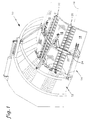
- FIG. 1 shows a partial perspective view of an exhaust nozzle for a gas turbine engine.
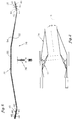
- FIG.2 is a diagrammatic illustration showing an exhaust nozzle.
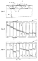
- FIG.3 is a hot-side view of a flap seal.
- FIG.4 is a side view of the flap seal shown in FIG.3, partially cut-away.
- FIG.5 is a cold-side view of the flap seal shown in FIG.3.
- FIG.6 is a sectional view of the flap seal shown in FIG.3.
- FIG.7 is a sectional view of the flap seal shown in FIG.3.
- FIG.8 is a diagrammatic partial view of the hot side of the seal showing a particular face segment embodiment.
- FIG.9 is a diagrammatic partial view of the hot side of the seal showing another face segment embodiment.
- a gas turbine engine includes an exhaust nozzle 10 comprising a convergent section 12 upstream of a divergent section 14. Both the convergent 12 and the divergent 14 sections are symmetrically arranged about the longitudinal axis 16 of the engine, although the divergent section 14 may skewed from the axis 16.
- FIG.2 shows a diagrammatic representation of a divergent section skewed an angle ⁇ from the longitudinal axis 16 of the engine.
- the divergent section 14 includes a plurality of flaps 18 and flap seals 20 pivotally attached to the convergent section 12 on one end.
- Mechanical linkage 22 links the flaps 18 and the flap seals 20 together, such that actuating said flaps causes said seals to actuate in like manner.
- a second mechanical linkage 24, attached to each of the flaps 18, actuates the flaps 18 and flap seals 20 about the longitudinal axis 16, or about an axis skewed relative to the longitudinal axis 16, or both.
- United States Patent No. 5,238,189 discloses an example of the aforementioned linkages 22,24.
- each flap seal 20 includes a body 26, a spine member 28, and a plurality of face segments 30.
- FIG.3 shows a "hot-side" view of a flap seal 20.
- the hot-side of the flap seal 20 is defined as that side which is directly exposed to exhaust gases exiting the engine.
- the cold-side of the flap seal 20 is defined as the side of the flap seal 20 opposite that which is directly exposed to exhaust gases.
- the body 26 may be described as having a length 32 and a width 34, as is shown in FIGS. 3 and 5.
- the body 26 further includes a plurality of corrugations 36 formed in the body 26, extending across the body width 34, and a first 38 and a second 40 channel (see FIG.6 also). In the preferred embodiment, the corrugations 36 are formed in the body 26 by a press (not shown).
- a press not shown.
- the first 38 and second 40 channel are formed along the width edges 42,44 of the body 26 by folding the edges of the body 26 sheet metal back over into a "U" shape.
- the walls 46 of the "U” extend lengthwise along the body 26.
- a spacer 48 having a predetermined thickness is inserted into each channel 38,40 and spot welded into place.
- each face segment 30 includes a midsection 50, having an inner 52 and an outer 54 surface, a first edge 56, a second edge 58, a first end 60, and a second end 62.
- the edges 56,58 are parallel with each other and substantially perpendicular with the ends 60,62.
- Each face segment 30 further includes a first flange 64 and a second flange 66.
- the first flange 64 is attached to the first edge 56 of the midsection 50.
- the second flange 66 is attached to the second edge 58 of the midsection 50.
- the first 64 and second 66 flanges are formed by bending sections of the face segment 30 away from the midsection 50.
- the face segments 30 may be formed from a sheet metal blank.
- the first 64 and second 66 flanges comprise mating geometries such that when face segments 30 are positioned adjacent each other, the first flange 64 of one face segment 30 couples with the second flange 66 of the adjacent face segment 30.
- FIG.7 shows the preferred embodiment of the first 64 and second 66 flanges.
- the first flange 64 is perpendicular to the midsection 50.
- the second flange 66 is "L" shaped; i.e., it includes a first section 68 perpendicular to the midsection 50 and a second section 70 parallel to the midsection 50.
- the end face segment 72 includes only one of the first 64 or second 66 flanges (see FIG.7) and is extended in the midsection 50.
- the end face segment 72 and body 26 When assembled with the body 26, the end face segment 72 and body 26 create a pocket 74 (shown in phantom) for receiving a hinge means 76 for pivotally attaching the seal 20.
- United States Patent No. 5,238,189 discloses such a hinge means 76.
- the face segments 30 further comprise a scallop 78 extending along either the first 56 or second 58 edge, or both.
- the scallops 78 decrease the distance between the first 56 and second 58 edges in a particular face segment 30 and increase the distance between edges 56,58 of adjacent face segments 30 to permit greater thermal growth in a particular area of the seal 20.
- the scallops 78 may be placed in the center region of all face segments 30 if the seal 20 is to experience a steep thermal gradient in the center region along the entire length of the seal 20.
- the face segments 30 in that particular area may include scallops 78 to allow for greater thermal expansion in that particular area; i.e., hot spots at one end of the seal 20 or along the width edges 42,44, etc.
- FIG. 8 shows scallops 78 near the ends 60,62 of the face segments 30 to allow for thermal expansion near the ends 60,62 and to facilitate translation within the channels 38,40.
- the spine member 28 is a rigid member attached to the cold-side of the body 26, attached by weld, braze, or other conventional fastener to the corrugations 36 of the body 26.
- the spine member 28 includes means 80 for attaching the flap seal 20 to the linkage 24 (FIG. 1) which connects the flaps 18 and flap seals 20 together.
- the face segments 30 are attached to the corrugations 36 of the body 26 by spot welds 90 (see FIG. 3 also).
- the face segments 30 are sized and positioned such that the first flange 64 and second flange 66 of adjacent face segments 30 nest together, separated by a predetermined gap 82.
- the gap 82 is sized to allow the expected thermal expansion of adjacent face segments 30.
- the mating geometries of the first 64 and second 66 flanges substantially prevent gases passing along the outer surface 54 of the face segments 30 from passing between the face segments 30.
- the ends 60,62 of the segments 30 are free to translate within the channels 38,40 (FIG. 6).
- the spacers 48 positioned in the channels 38,40, inboard of the ends 60,62, help to maintain a channel gap 84 sufficient to prevent binding of the face segments 30.
- the spacers 48 also help position the face segments 30 during assembly.
- At least the invention provides an exhaust nozzle flap seal capable of withstanding the mechanical load associated with a vectorable exhaust nozzle. It also provides an exhaust nozzle flap seal capable of withstanding the thermal load associated with a vectorable exhaust nozzle. It also provides an exhaust nozzle flap seal that minimally distorts in response to a thermal load. It also provides an exhaust nozzle flap seal that improves sealing between flaps in a vectorable exhaust nozzle.
Landscapes
- Engineering & Computer Science (AREA)
- Chemical & Material Sciences (AREA)
- Combustion & Propulsion (AREA)
- Mechanical Engineering (AREA)
- General Engineering & Computer Science (AREA)
- Gasket Seals (AREA)
Applications Claiming Priority (2)
| Application Number | Priority Date | Filing Date | Title |
|---|---|---|---|
| US08/349,116 US5667140A (en) | 1994-12-02 | 1994-12-02 | Engine exhaust nozzle seal |
| US349116 | 1994-12-02 |
Publications (3)
| Publication Number | Publication Date |
|---|---|
| EP0715067A2 true EP0715067A2 (fr) | 1996-06-05 |
| EP0715067A3 EP0715067A3 (fr) | 1996-10-23 |
| EP0715067B1 EP0715067B1 (fr) | 2000-08-23 |
Family
ID=23370979
Family Applications (1)
| Application Number | Title | Priority Date | Filing Date |
|---|---|---|---|
| EP95308613A Expired - Lifetime EP0715067B1 (fr) | 1994-12-02 | 1995-11-29 | Volet d'étanchéitée pour une tuyère de réaction |
Country Status (4)
| Country | Link |
|---|---|
| US (1) | US5667140A (fr) |
| EP (1) | EP0715067B1 (fr) |
| JP (1) | JP3671306B2 (fr) |
| DE (1) | DE69518494T2 (fr) |
Cited By (3)
| Publication number | Priority date | Publication date | Assignee | Title |
|---|---|---|---|---|
| FR2857414A1 (fr) * | 2003-07-08 | 2005-01-14 | Snecma Moteurs | Volet souple de tuyere a section variable de turbomachine |
| WO2014197030A2 (fr) | 2013-03-12 | 2014-12-11 | United Technologies Corporation | Dispositif de commande d'écoulement à coque expansible |
| EP3536943A1 (fr) * | 2018-03-05 | 2019-09-11 | Rolls-Royce plc | Buse d'aéronef |
Families Citing this family (11)
| Publication number | Priority date | Publication date | Assignee | Title |
|---|---|---|---|---|
| US6745570B2 (en) | 2002-02-01 | 2004-06-08 | General Electric Co. | Methods and apparatus for sealing gas turbine engine nozzles using a flap system |
| US6658854B2 (en) | 2002-02-01 | 2003-12-09 | General Electric Co. | Methods and apparatus for retaining gas turbine engine nozzle basesheets |
| US7302793B2 (en) * | 2003-10-29 | 2007-12-04 | General Electric Company | Methods and apparatus to reduce turbine engine nozzle basesheet stresses |
| US7240493B2 (en) * | 2003-12-01 | 2007-07-10 | The University Of Mississippi | Method and device for reducing engine noise |
| US6935118B2 (en) * | 2003-12-19 | 2005-08-30 | General Electric Company | Exhaust nozzle segmented basesheet and production method thereof |
| US7096661B2 (en) * | 2004-03-26 | 2006-08-29 | United Technologies Corporation | Axial divergent section slot nozzle |
| US8122722B2 (en) * | 2008-02-29 | 2012-02-28 | General Electric Company | Exhaust nozzle seal with segmented basesheet disposed between side rails |
| US8156745B2 (en) * | 2008-02-29 | 2012-04-17 | General Electric Company | Exhaust nozzle seal with segmented basesheet |
| US8015820B2 (en) * | 2008-06-03 | 2011-09-13 | United Technologies Corporation | Gas turbine engine exhaust component and manufacturing method of same |
| EP3008321B1 (fr) * | 2013-06-14 | 2018-11-14 | Saab AB | Buse d'éjection variable pour un moteur à réaction et procédé de variation de la buse |
| EP3008320B1 (fr) * | 2013-06-14 | 2020-07-29 | Saab Ab | Tuyère d'éjection convergente-divergente à géométrie variable pour un moteur à réaction et procédé permettant de modifier la tuyère |
Citations (1)
| Publication number | Priority date | Publication date | Assignee | Title |
|---|---|---|---|---|
| US5238189A (en) | 1992-07-16 | 1993-08-24 | United Technologies Corporation | Convergent-to-divergent seal hinge for a convergent/divergent nozzle |
Family Cites Families (15)
| Publication number | Priority date | Publication date | Assignee | Title |
|---|---|---|---|---|
| US2910828A (en) * | 1956-08-24 | 1959-11-03 | United Aircraft Company | Convergent-divergent variable area propulsion nozzle |
| GB1381503A (en) * | 1971-06-11 | 1975-01-22 | Rolls Royce | Variable area nozzle for a gas turbine engine |
| GB1605260A (en) * | 1974-09-07 | 1986-11-12 | Rolls Royce | Gas turbine engines |
| US4176792A (en) * | 1977-07-11 | 1979-12-04 | General Electric Company | Variable area exhaust nozzle |
| US4637550A (en) * | 1985-10-01 | 1987-01-20 | The United States Of America As Represented By The Secretary Of The Air Force | Dual material exhaust nozzle flap |
| US4690330A (en) * | 1985-12-02 | 1987-09-01 | United Technologies Corporation | Louvered seal flap edge stiffener |
| US4662566A (en) * | 1985-12-02 | 1987-05-05 | United Technologies Corporation | Louvered seal flap for flap-type nozzle |
| US5039014A (en) * | 1989-04-11 | 1991-08-13 | General Electric Company | Axisymmetric vectoring exhaust nozzle seal |
| US4994660A (en) * | 1989-04-11 | 1991-02-19 | Hitachi, Ltd. | Axisymmetric vectoring exhaust nozzle |
| CN1022433C (zh) * | 1989-04-11 | 1993-10-13 | 通用电气公司 | 轴线对称转向排气喷口密封装置 |
| US5076496A (en) * | 1990-02-05 | 1991-12-31 | General Electric Company | Exhaust nozzle flap seal |
| US5082182A (en) * | 1990-08-23 | 1992-01-21 | United Technologies Corporation | Thrust vectoring exhaust nozzle |
| US5215257A (en) * | 1992-07-16 | 1993-06-01 | United Technologies Corporation | Divergent seal arrangement for a convergent/divergent nozzle |
| US5215256A (en) * | 1992-07-16 | 1993-06-01 | Barcza W Kevin | Flap hinge arrangement for a convergent/divergent nozzle |
| US5285637A (en) * | 1992-11-02 | 1994-02-15 | United Technologies Corporation | Seal centering and restraining device for an axisymmetric convergent/divergent nozzle |
-
1994
- 1994-12-02 US US08/349,116 patent/US5667140A/en not_active Expired - Lifetime
-
1995
- 1995-11-29 DE DE69518494T patent/DE69518494T2/de not_active Expired - Lifetime
- 1995-11-29 EP EP95308613A patent/EP0715067B1/fr not_active Expired - Lifetime
- 1995-11-30 JP JP33421395A patent/JP3671306B2/ja not_active Expired - Fee Related
Patent Citations (1)
| Publication number | Priority date | Publication date | Assignee | Title |
|---|---|---|---|---|
| US5238189A (en) | 1992-07-16 | 1993-08-24 | United Technologies Corporation | Convergent-to-divergent seal hinge for a convergent/divergent nozzle |
Cited By (7)
| Publication number | Priority date | Publication date | Assignee | Title |
|---|---|---|---|---|
| FR2857414A1 (fr) * | 2003-07-08 | 2005-01-14 | Snecma Moteurs | Volet souple de tuyere a section variable de turbomachine |
| EP1503068A1 (fr) * | 2003-07-08 | 2005-02-02 | Snecma Moteurs | Volet souple de tuyère à section variable de turbomachine |
| US7013650B2 (en) | 2003-07-08 | 2006-03-21 | Snecma Moteurs | Flexible flap for a variable-section turbomachine nozzle |
| RU2341673C2 (ru) * | 2003-07-08 | 2008-12-20 | Снекма Моторс | Гибкая заслонка сопла с переменным сечением газотурбинного двигателя и сопло газотурбинного двигателя |
| WO2014197030A2 (fr) | 2013-03-12 | 2014-12-11 | United Technologies Corporation | Dispositif de commande d'écoulement à coque expansible |
| EP2971657A4 (fr) * | 2013-03-12 | 2016-10-19 | United Technologies Corp | Dispositif de commande d'écoulement à coque expansible |
| EP3536943A1 (fr) * | 2018-03-05 | 2019-09-11 | Rolls-Royce plc | Buse d'aéronef |
Also Published As
| Publication number | Publication date |
|---|---|
| EP0715067A3 (fr) | 1996-10-23 |
| US5667140A (en) | 1997-09-16 |
| DE69518494D1 (de) | 2000-09-28 |
| DE69518494T2 (de) | 2001-01-04 |
| JPH08226351A (ja) | 1996-09-03 |
| EP0715067B1 (fr) | 2000-08-23 |
| JP3671306B2 (ja) | 2005-07-13 |
Similar Documents
| Publication | Publication Date | Title |
|---|---|---|
| EP0715067B1 (fr) | Volet d'étanchéitée pour une tuyère de réaction | |
| EP0744544B1 (fr) | Volet d'étanchéitée pour une tuyère de réaction | |
| EP0682744B1 (fr) | Agencement de joint divergent pour tuyere convergente-divergente | |
| US4813608A (en) | Bimetallic air seal for exhaust nozzles | |
| US5485959A (en) | Axisymmetric vectoring exhaust nozzle thermal shield | |
| US5689954A (en) | Exhaust gas manifold for an internal combustion engine and method of making such exhaust gas manifold | |
| JP4256709B2 (ja) | ガスタービンエンジンの燃焼器用の環状一体形の波形ライナ | |
| EP1820954A1 (fr) | Buse convergente/divergente dotée de joints divergents supportés | |
| US6203025B1 (en) | Seal | |
| EP1764498B1 (fr) | Tuyère convergente-divergente avec volets entrecroisés divergents | |
| US5232158A (en) | Convergent/divergent nozzle with seal centering | |
| US6993914B2 (en) | Convergent-divergent turbojet nozzle | |
| US4690330A (en) | Louvered seal flap edge stiffener | |
| US5897120A (en) | Outer flap elastic seal assembly | |
| JPH0256177B2 (fr) | ||
| US5820024A (en) | Hollow nozzle actuating ring | |
| US4892254A (en) | Aircraft engine interface fairing support | |
| EP1544448B1 (fr) | Feuille de base segmentée pour une tuyère et procédé de fabrication correspondant | |
| EP2096292B1 (fr) | Joint de tuyère d'échappement avec panneau de base segmenté déposé entre des rails latéraux | |
| US4541567A (en) | Variable area nozzle vane | |
| US5566884A (en) | Supersonic nozzle for a turbojet engine | |
| US7302793B2 (en) | Methods and apparatus to reduce turbine engine nozzle basesheet stresses | |
| JP2003014180A (ja) | 管継手構造、およびその管継手構造を備えた燃焼器、並びにその燃焼器を備えたガスタービン |
Legal Events
| Date | Code | Title | Description |
|---|---|---|---|
| PUAI | Public reference made under article 153(3) epc to a published international application that has entered the european phase |
Free format text: ORIGINAL CODE: 0009012 |
|
| AK | Designated contracting states |
Kind code of ref document: A2 Designated state(s): DE FR GB |
|
| PUAL | Search report despatched |
Free format text: ORIGINAL CODE: 0009013 |
|
| AK | Designated contracting states |
Kind code of ref document: A3 Designated state(s): DE FR GB |
|
| RHK1 | Main classification (correction) |
Ipc: F02K 1/80 |
|
| 17P | Request for examination filed |
Effective date: 19970409 |
|
| 17Q | First examination report despatched |
Effective date: 19990115 |
|
| GRAG | Despatch of communication of intention to grant |
Free format text: ORIGINAL CODE: EPIDOS AGRA |
|
| GRAG | Despatch of communication of intention to grant |
Free format text: ORIGINAL CODE: EPIDOS AGRA |
|
| GRAH | Despatch of communication of intention to grant a patent |
Free format text: ORIGINAL CODE: EPIDOS IGRA |
|
| GRAH | Despatch of communication of intention to grant a patent |
Free format text: ORIGINAL CODE: EPIDOS IGRA |
|
| GRAA | (expected) grant |
Free format text: ORIGINAL CODE: 0009210 |
|
| AK | Designated contracting states |
Kind code of ref document: B1 Designated state(s): DE FR GB |
|
| REF | Corresponds to: |
Ref document number: 69518494 Country of ref document: DE Date of ref document: 20000928 |
|
| ET | Fr: translation filed | ||
| PLBE | No opposition filed within time limit |
Free format text: ORIGINAL CODE: 0009261 |
|
| STAA | Information on the status of an ep patent application or granted ep patent |
Free format text: STATUS: NO OPPOSITION FILED WITHIN TIME LIMIT |
|
| 26N | No opposition filed | ||
| REG | Reference to a national code |
Ref country code: GB Ref legal event code: IF02 |
|
| PGFP | Annual fee paid to national office [announced via postgrant information from national office to epo] |
Ref country code: FR Payment date: 20081106 Year of fee payment: 14 |
|
| REG | Reference to a national code |
Ref country code: FR Ref legal event code: ST Effective date: 20100730 |
|
| PG25 | Lapsed in a contracting state [announced via postgrant information from national office to epo] |
Ref country code: FR Free format text: LAPSE BECAUSE OF NON-PAYMENT OF DUE FEES Effective date: 20091130 |
|
| PGFP | Annual fee paid to national office [announced via postgrant information from national office to epo] |
Ref country code: DE Payment date: 20121121 Year of fee payment: 18 |
|
| PGFP | Annual fee paid to national office [announced via postgrant information from national office to epo] |
Ref country code: GB Payment date: 20121128 Year of fee payment: 18 |
|
| GBPC | Gb: european patent ceased through non-payment of renewal fee |
Effective date: 20131129 |
|
| PG25 | Lapsed in a contracting state [announced via postgrant information from national office to epo] |
Ref country code: DE Free format text: LAPSE BECAUSE OF NON-PAYMENT OF DUE FEES Effective date: 20140603 |
|
| REG | Reference to a national code |
Ref country code: DE Ref legal event code: R119 Ref document number: 69518494 Country of ref document: DE Effective date: 20140603 |
|
| PG25 | Lapsed in a contracting state [announced via postgrant information from national office to epo] |
Ref country code: GB Free format text: LAPSE BECAUSE OF NON-PAYMENT OF DUE FEES Effective date: 20131129 |