EP0715214A1 - Verfahren zur Positionierung einer Maske bezüglich eines Werkstücks und Vorrichtung zur Durchführung des Verfahrens - Google Patents
Verfahren zur Positionierung einer Maske bezüglich eines Werkstücks und Vorrichtung zur Durchführung des Verfahrens Download PDFInfo
- Publication number
- EP0715214A1 EP0715214A1 EP95118791A EP95118791A EP0715214A1 EP 0715214 A1 EP0715214 A1 EP 0715214A1 EP 95118791 A EP95118791 A EP 95118791A EP 95118791 A EP95118791 A EP 95118791A EP 0715214 A1 EP0715214 A1 EP 0715214A1
- Authority
- EP
- European Patent Office
- Prior art keywords
- workpiece
- mask
- alignment
- light
- alignment marks
- Prior art date
- Legal status (The legal status is an assumption and is not a legal conclusion. Google has not performed a legal analysis and makes no representation as to the accuracy of the status listed.)
- Granted
Links
Images


Classifications
-
- G—PHYSICS
- G03—PHOTOGRAPHY; CINEMATOGRAPHY; ANALOGOUS TECHNIQUES USING WAVES OTHER THAN OPTICAL WAVES; ELECTROGRAPHY; HOLOGRAPHY
- G03F—PHOTOMECHANICAL PRODUCTION OF TEXTURED OR PATTERNED SURFACES, e.g. FOR PRINTING, FOR PROCESSING OF SEMICONDUCTOR DEVICES; MATERIALS THEREFOR; ORIGINALS THEREFOR; APPARATUS SPECIALLY ADAPTED THEREFOR
- G03F9/00—Registration or positioning of originals, masks, frames, photographic sheets or textured or patterned surfaces, e.g. automatically
- G03F9/70—Registration or positioning of originals, masks, frames, photographic sheets or textured or patterned surfaces, e.g. automatically for microlithography
-
- H—ELECTRICITY
- H10—SEMICONDUCTOR DEVICES; ELECTRIC SOLID-STATE DEVICES NOT OTHERWISE PROVIDED FOR
- H10P—GENERIC PROCESSES OR APPARATUS FOR THE MANUFACTURE OR TREATMENT OF DEVICES COVERED BY CLASS H10
- H10P95/00—Generic processes or apparatus for manufacture or treatments not covered by the other groups of this subclass
Definitions
- the invention relates to a process for positioning a mask relative to a workpiece and a device for performing th process in an exposure device which is used especially for production of a semiconductor device, a printed circuit board, an LCD (liquid crystal display) and for similar purposes.
- the invention relates especially to positioning of a mask relative to a workpiece in an exposure device of a projection exposure system, which can be done automatically and at the same time with high accuracy.
- Production of electrical and electronic components and parts of various types in which processing of structures in the micron range is necessary includes an exposure process.
- These electronic parts are semiconductor components, liquid crystal displays, printer heads of the inkjet type, and multichip modules in which a host of different electronic components are produced on a substrate and thus a module is formed, and the like.
- a mask is used in which a pattern has been formed on a transparent substrate, such as glass or the like, by vapor deposition and etching of a metal, such as chromium or the like.
- a workpiece is irradiated with ultraviolet rays, and thus, the mask pattern is transferred to the photoresist applied to the workpiece.
- These exposure systems are generally divided into a projection exposure system, a contact exposure system and a proximity exposure system.
- a projection exposure system a mask image is formed on the workpiece by means of a projection lens.
- the contact exposure system parallel light is emitted in a state in which the mask and the workpiece are located tightly against one another.
- the parallel light is emitted in a state in which a small intermediate space is formed between the mask and the workpiece.
- FIG. 9 schematically shows an arrangement of a conventional exposure device of the projection type.
- a light irradiation device 1 has a lamp 1a, a focussing mirror 1b, a shutter 1c, an optical filter 1d and a condenser lens 1e.
- a mask carrier 2 has a mask M that is attached thereon.
- a mask pattern and mask alignment marks MAM (hereafter, "mask marks") are recorded on mask M for purposes of positioning.
- a projection lens 3 and a workpiece W are successively positioned below the mask.
- the workpiece W has workpiece alignment marks WAM (hereafter "workpiece marks") recorded thereon for purposes of positioning.
- Workpiece W is mounted on a workpiece carrier 4.
- An alignment unit 5 which consists of a lens 5a, objective lens 5b, semitransparent mirror 5c and image converter 5d comprising a CCD camera.
- the workpiece mark WAM and mask mark MAM projected onto the workpiece W are detected via the semitransparent mirror 5c, objective lens 5b and the lens 5a by means of image converter 5d, and thus, the positions of the two marks are observed.
- the alignment unit 5 can be located, besides in area B as shown, also in an additionally shown area A or in an additionally shown area C.
- TTL the method of determination of the mask alignment marks MAM projected onto the workpiece of this type by the projection lens
- exposure light is then emitted from light irradiation device 1, the mask pattern is projected onto workpiece W and exposure is effected.
- the alignment light here, either exposure light or nonexposure light is used.
- exposure light is defined as light which is used when the mask pattern is projected onto the workpiece and exposure i effected, and which has wavelengths at which the photosensitive agent applied to the workpiece, such as a photoresist or the like, has sensitivity.
- exposure light for example an i-line, a h-line or a g-line (i-line: 365 nm wavelength, h-line: 405 nm wavelength, g-line: 436 nm wavelength) is used.
- nonexposure light is defined as light with wavelengths at which the photosensitive agent applied to the workpiece does not have sensitivity.
- an e-line, a d-line or a c-line (e-line: 546 nm wavelength, d-line: 588 nm wavelength, c-line: 656 nm wavelength) is used.
- the advantage arises that areas can be formed for the alignment marks in small gaps between the circuit pattern areas, and that the areas for the circuit patterns are not limited by the positioning area, since the photoresist is not exposed to the action of exposure light during positioning.
- the alignment light is transmitted only according to the areas of the alignment marks located on the mask and emitted to the workpiece. If the irradiation surface on the workpiece with this transmission light is small, there are cases in which the workpiece marks are not irradiated with this transmission light and in which the image converter cannot determine the workpiece mark. As a result, auto alignment can no longer be done, in which the image converter determines both the workpiece mark and the mask mark, in which the control device recognizes them, and in which positioning of the mask to the workpiece is done on this basis.
- a primary object of the present invention is to devise a process for positioning of a mask relative to a workpiece in which the relative positions of the mask marks and the workpiece marks can be easily recognized.
- Another object of the invention is to devise a device to execute the process.
- positioning is done by emitting, from a first light irradiation part, alignment light onto the alignment marks of a mask, by recording the projected images of the alignment marks of the mask and subjecting them to image processing, by determining/storing the relative positions, by subsequently stopping emission of the light from the first light irradiation part, by emitting alignment light from a second light irradiation part onto the workpiece alignment marks, by recording the workpiece alignment marks and subjecting them to image processing, by determining/storing the relative positions, by computing the data of the relative positions of the above described two alignment marks, and by moving the workpiece and/or the mask such that the above described two alignment marks come to rest on top of one another.
- a positioning device has a mask, a mask carrier for executing movement of the above described mask, a projection lens, a workpiece, a workpiece carrier for executing movement of the above described workpiece, a first light irradiation part for irradiation of alignment marks of the mask with alignment light, a second light irradiation part for irradiation of alignment marks of the workpiece with alignment light, a camera means which records the projected images of the mask alignment marks by the alignment light emitted from the first light irradiation part, records the workpiece alignment marks which are illuminated by the alignment light emitted from the second light irradiation part, and a control means which, based on the video data recorded by the camera means, controls the movement of the mask carrier and the workpiece carrier, that the control means records the mask alignment marks and undergoes image processing and determines/stores the relative positions thereof, if from the first light irradiation part, the exposure light is emitted
- the above described object is further achieved, according to the invention, by executing a process for positioning of a mask relative to a workpiece in which the exposure light is emitted as alignment light from a first light irradiation part onto the mask alignment marks, the mask alignment marks are projected and imaged onto a reflection component which is located in a workpiece carrier, the projected images are recorded and undergo image processing, the relative positions thereof are determined/stored, then emission of the exposure light from the first light irradiation part, as alignment light is stopped, a workpiece is placed on the workpiece carrier, and from the first light irradiation part or a second light irradiation part alignment light is emitted onto the workpiece alignment marks.
- the workpiece alignment marks are recorded and undergo image processing, relative positions are determined/stored, the data of the relative positions of the two alignment marks are computed and the workpiece and/or the mask is/are moved such that the pair of alignment marks come to rest on top of one another.
- the noted objects are also attainable by a mirror and an auxiliary imaging lens being used as the reflection part located on the workpiece carrier, being arranged such that, in one surface position of the workpiece placed on the workpiece carrier, projected images of the mask alignment marks are imaged.
- a device for positioning a mask to a workpiece has a mask, a mask carrier for executing movement of the mask, a projection lens, a workpiece, a workpiece carrier for executing movement of the workpiece, a first light irradiation part for irradiation of alignment marks of the mask with alignment light, a reflection component which is located on the workpiece carrier and in which projected images of the mask alignment marks are produced using exposure light as alignment light which is emitted from the first light irradiation part, a camera means which records the projected images of the mask alignment marks and records the workpiece alignment marks which are illuminated by the alignment light emitted from the first light irradiation part or a second light irradiation part, and a control means which, based on the video data recorded by the camera means, controls the movements of the mask carrier and the workpiece carrier, where the control means records the mask alignment marks projected onto the reflection component, undergoes image processing and determines/stores the relative positions thereof
- the relative positions of the two alignment marks were determined in a state in which the mask marks were projected onto the workpiece provided with the workpiece marks. Determination of the workpiece marks was therefore difficult in the case in which the surface on the workpiece irradiated by the transmission light which is transmitted only according to the areas of the alignment marks, as was described above, is small.
- the workpiece marks can be determined regardless of the surface on the workpiece irradiated by the above described transmission light, and the mask can be easily positioned relative to the workpiece by means of the measure by which the alignment light from the first light irradiation part is separately emitted in steps onto the mask marks, and the alignment light from the second light irradiation part is separately emitted in steps onto the workpiece marks, by which the respective images are recorded separately, and by which, based on the respective recorded images, the position coordinates thereof are determined.
- the positions of the workpiece marks can be determined by means of the measure in which, the workpiece carrier has a reflection component in which the exposure light is emitted as alignment light onto the mask in a state in which the workpiece is not placed on the workpiece carrier, in which the positions of the projected images of the mask marks which are imaged by the reflection component are determined and stored, and in which, then, the workpiece is placed on the workpiece carrier and is irradiated with the alignment light.
- the positions of the mask marks and the workpiece marks can, likewise, be recognized separately. Therefore, the workpiece marks can be determined regardless of the surface on the workpiece irradiated by the transmission light which is transmitted only according to the areas of the mask alignment marks, the relative positions of the mask marks and the workpiece marks can be determined, and the mask can be easily positioned to the workpiece.
- exposure light which does not produce any imaging error or aberration, respectively, as it passes through the projection lens as alignment light can be used by the measure by which alignment light is emitted in a state in which the workpiece is not placed on the workpiece carrier.
- a mirror and an auxiliary imaging lens can also be used as the reflection component which is located on the workpiece carrier, instead of using the mirror installed on the surface of the workpiece carrier.
- the imaging positions of the projected images of the mask marks can be brought into agreement with the positions on the workpiece surface at a time at which the workpiece is later placed on the workpiece carrier. It, therefore, becomes possible, after completion of positioning of the mask relative to the workpiece, to transmit the mask pattern by exposure onto the workpiece without moving the workpiece carrier in the Z-axis direction.
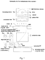
- Fig. 1 is a schematic of a first embodiment of the invention.
- a light irradiation device 1 has a lamp 1a, such as a high pressure mercury lamp or the like, which emits light which contains exposure light, a focussing mirror 1b, a shutter 1c, an optical filter 1d which is used in irradiation with the nonexposure light, and a condenser lens 1e.
- mask carrier 2 which is driven in the X-Y-Z- ⁇ directions by means of a drive device (not shown), carries a mask M on which a mask pattern to be transmitted in a conventional exposure process and mask alignment marks MAM are recorded for positioning of mask M relative to the workpiece W prior to performing the exposure process.
- a projection lens 3 is disposed below the mask.
- a workpiece W on which workpiece alignment marks WAM are recorded for purposes of positioning is positioned on a workpiece carrier 4 which is driven in the X-Y-Z- ⁇ directions by means of a drive device which is not shown.
- a workpiece alignment mark partial illumination system is designated WA1.
- Nonexposure light from a light source (not shown) is incident on semitransparent mirror 5e of alignment unit 5 via optical fibers 6a, lens 6b and a mirror 6c and irradiates the workpiece mark WAM on workpiece W via lens 5b and semitransparent mirror 5c.
- the alignment unit 5 comprises lens 5a, objective lens 5b, semitransparent mirrors 5c and 5e and the image converter 5d which has the CCD camera.
- the mask mark MAM which is projected onto the workpiece W and the workpiece mark WAM irradiated by the workpiece alignment mark partial illumination system WA1 are detected via semitransparent mirror 5c, objective lens 5b, semitransparent mirror 5e and lens 5a of image converter 5d. If, in this case, semitransparent mirror 5c has a certain thickness, deviation of the optical path of the alignment light of the mask, and thus, a change of the position in which mask mark MAM is determined occur. In this case, a corresponding correction is necessary.
- Semitransparent mirror 5c ordinarily is formed of a resin film, for example, a pellicle with a thickness of roughly a few microns or the like. In this way, the above described influence of the thickness is reduced to the degree at which problems which are negligible with respect to use occur.
- alignment unit 5 and partial illumination system WA1 are each shown only one. However, there are several alignment units 5 (at least at two points), since on the mask M and workpiece W each have several mask marks MAM and several workpiece marks WAM (at least two points each), and since an alignment unit 5 is assigned to each alignment mark.
- Alignment units 5 are, furthermore, ordinarily formed such that they can be removed in the direction of the arrow in the drawing. During exposure, alignment units 5 when positioned extending within an exposure area are thus removed.
- Fig. 2 is a schematic of a control system arrangement for the device shown in Fig. 1.
- a control console 11 an arithmeticlogic unit 12 for control of the projection exposure device and a carrier controlling element 13 which controls the positions of the mask carrier 2 and workpiece carrier 4 in the X-Y-Z- ⁇ directions.
- An image processing part 14 which recognizes mask mark MAM recorded by means of image converter 5d of alignment unit 5, stores the position coordinates of the MAM, then recognizes workpiece mark WAM recorded by means of image converter 5d of alignment unit 5 and determines the position coordinates of the WAM, as is described below. Furthermore, arithmetic-logic unit 12 determines the difference between the position coordinates of mask mark MAM and the position coordinates of workpiece mark WAM which have been determined in image processing part 14. Carrier controlling element 13, then, moves the mask carrier 2 and/or workpiece carrier 4 so as to bring the two position coordinates into agreement with one another. The mask marks MAM and workpiece the marks WAM recorded by alignment units 5 are displayed on a monitor 15.
- mask carrier 2 and workpiece carrier 4 are moved with respect to projection lens 3, and thus, focal length correction is performed. Furthermore, there can be a device which moves projection lens 3 in the Z-axis direction, and thus, projection lens 3 and mask carrier 2 move, or projection lens 3 and workpiece carrier 4 move (reference is made to commonly assigned co-pending U.S. Patent Application SN. 08/540,390, filed October 6, 1995 for details of the above described focal length correction, said application being hereby incorporated by reference to the extent necessary to complete an understanding of this invention).
- the image of the workpiece mark WAM recorded by the image converter 5d is sent to image processing part 14, which identifies workpiece mark WAM and determines its position coordinates (XW, YW).
- the carrier controlling element 13 drives mask carrier 2 and/or workpiece carrier 4 in the X-Y- ⁇ directions to bring the position of mask mark MAM into agreement with the position of workpiece mark WAM based upon the above described position deviation.
- the positions of the workpiece marks WAM can also be reliably determined and positioning can be achieved within a short time with high accuracy by the measure by which first the nonexposure light is emitted as alignment light, mask marks MAM are projected onto workpiece W and the position coordinates of the mask marks MAM are stored, and by which, then, emission of the above described nonexposure light is stopped, by partial illumination, the vicinity of workpiece marks WAM is irradiated and the position coordinates of the workpiece marks are determined, when a mask is used with which, in the conventional process, light is transmitted to an area that is based on the size of the mask marks MAM, the area on the workpiece irradiated by the transmission light becomes small.
- the positioning of the mask relative to the workpiece was done by recording the mask marks and the workpiece marks at the same time, based on the feature of the respective mark, by recognizing the above described respective mark and by determining the relative positions thereof. If the mask marks and the workpiece marks do not come to rest on top of one another and are completely separated from one another, there is, therefore, no problem since by means of the control device the overall shape of the mask can be exactly acquired and the feature of the respective mark can be evaluated.
- the control device was not able to recognize the features of the workpiece marks in spite of the presence of the mask marks and workpiece marks within the determination area.
- the control device cannot recognize them as a cross shape, if in some of these workpiece marks and mask marks come to rest on top of one another, since the workpiece marks in general have a lower contrast than the mask marks. Consequently, the workpiece marks cannot be recognized.
- the workpiece marks can be exactly evaluated by the measure wherein, from the first light irradiation part, the alignment light is emitted onto the mask marks, wherein the mask marks are projected and imaged onto workpiece W and the position coordinates of the mask marks are stored, wherein, subsequently, emission of the above described alignment light is stopped, wherein by the second light irradiation part, the vicinity of the workpiece marks is irradiated, and wherein, the position coordinates of workpiece marks WAM are thus determined, even in the case in which the mask marks and the workpiece marks come to rest on top of one another or in which the mask pattern is positioned in the vicinity of the mask marks.
- the position coordinates of the mask marks are determined, stored and then the position coordinates of the workpiece marks are determined.
- the same action can also be obtained by first determining and storing the position coordinates of the workpiece marks, and then determining the position coordinates of the mask marks.
- a mask alignment mark partial illumination system MA1 which is comprised of optical fibers 7a and mirror 7b, and which partially illuminates the peripheral area of mask mark MAM during alignment.
- the remainder of this arrangement is identical to the first embodiment shown in Fig. 1.
- the nonexposure light is emitted from light irradiation device 1 when mask marks MAM are imaged on workpiece W in order to position mask marks MAM relative to workpiece marks WAM (see steps (2) and (3) according to the first embodiment).
- mask mark MAM is imaged onto workpiece W by partially illuminating the peripheral area of mask mark MAM by the above described mask alignment mark partial illumination system MA1. Other process steps for positioning are identical to the above described first embodiment.
- the pattern In the case of emission of exposure light from the partial illumination system MA1, the pattern cannot, however, be located in the vicinity of the alignment mark which may be irradiated by the exposure light, since the exposure light irradiates not only mask mark MAM (workpiece mark WAM), but also the peripheral area thereof.
- mask marks MAM can be imaged on workpiece W by the arrangement of mask alignment mark partial illumination systems MA1, not only by the nonexposure light, but by the exposure light. In this way, activation to correct the imaging error of the nonexposure light and the exposure wavelength is no longer necessary. Furthermore, an application for a projection lens is enabled which has the characteristic that no focussing can be done by the nonexposure light. In this way, positioning of the mask marks relative to the workpiece marks is enabled without taking into account the characteristic of the projection lens.
- alignment light is defined as the light, including the exposure light and the nonexposure light, which is used for purposes of positioning of the mask marks relative to the workpiece marks.
- Fig. 4 is a schematic of third and fourth embodiments of the invention.
- the third embodiment of the invention instead of the workpiece alignment mark partial illumination system WA1 according to the first embodiment, there is a workpiece alignment mark partial illumination system WA2.
- workpiece alignment mark partial illumination system WA3 instead of workpiece alignment mark partial illumination system WA1 according to the first embodiment, there is workpiece alignment mark partial illumination system WA3.
- the remaining arrangement is identical to the first embodiment shown in Fig. 1.
- workpiece alignment mark partial illumination system WA2 there is workpiece alignment mark partial illumination system WA2.
- the workpiece alignment mark partial illumination system WA2 is inserted when photographing workpiece mark WAM by means of image converter 5d (step (8) according to the first embodiment).
- the nonexposure light is supplied via optical fibers 8a and irradiates workpiece mark WAM on the workpiece W via mirror 8b, projection lens 3 and the semitransparent mirror 5c.
- the other process steps are identical to the first embodiment.
- workpiece alignment mark partial illumination system WA3 there is workpiece alignment mark partial illumination system WA3.
- the workpiece alignment mark partial illumination system WA3 is inserted when photographing workpiece mark WAM by means of image converter 5d (step (8) according to the first embodiment).
- the nonexposure light is supplied via optical fibers 9a and irradiates workpiece mark WAM on the workpiece W via lens 9b.
- the other process steps are identical to the first embodiment.
- the positions of workpiece marks WAM can be reliably recognized and positioning can be achieved in a short time with high precision, as in the first embodiment, by the measure wherein the mask marks MAM are projected onto workpiece W, the position coordinates of mask marks MAM are stored, subsequently the vicinity of workpiece marks WAM is irradiated by the partial illumination systems WA2, or the partial illumination systems WA3, and thus, the position coordinates of workpiece marks WAM are determined.
- alignment unit 5 and partial illumination system WA1 are integral with one another, as in the first embodiment, it is not necessary to adjust the position between the two. If, however, alignment unit 5 and partial illumination systems WA2 and WA3 are arranged as separate individual parts, as in the above described third and fourth embodiments, it is necessary to adjust their position relative to one another.
- nonexposure light is emitted from workpiece alignment mark partial illumination systems WA1, WA2, or WA3.
- exposure light can, likewise, be emitted.
- the above described third and fourth embodiments can be applied to the second embodiment, and the non-exposure light or exposure light can be emitted from mask alignment mark partial illumination systems MA1.
- a total reflection or semitransparent mirror 4a is installed on workpiece carrier 4. It is desirable that above mirror 4a is a semitransparent mirror.
- Mask mark MAM is imaged in mirror 4a located in workpiece carrier 4, and the workpiece mark WAM is irradiated by the above described workpiece alignment mark partial illumination system WA1.
- alignment unit 5 they are both recorded via the semitransparent mirror 5c, the objective lens 5b, the semitransparent 5e and the lens 5a by means of the image converter 5d.
- Semitransparent mirror 5c consists, as was described above, of a resin film, for example a pellicle with a thickness of roughly a few microns or the like.
- Alignment unit 5 and partial illumination system WA1 are, furthermore, located at least at two points according to the number of mask marks and workpiece marks. This embodiment, furthermore, has the same system arrangement as in Fig. 2.
- the image of the workpiece mark WAM recorded by means of the image converter 5d is sent to the image processing unit 14 which identifies workpiece mark WAM and determines its position coordinates (XW, YW).
- optical filter 1d can also be inserted into the light irradiation device 1 and the entire surface of workpiece W can be irradiated by nonexposure light emitted from light irradiation device 1.
- the mask patten is projected onto workpiece W. If, however, the workpiece carrier 4 is located in position Zo in the drawing, the mask pattern is not imaged onto workpiece W since, conventionally, as the result of the imaging error of projection lens 3, the focal position of the mask pattern due to the exposure light differs from the focal position of the mask pattern by the nonexposure light. In this case, workpiece mark WAM and mask mark MAM are not shown due to the fact that they come to rest on top of one another.
- Carrier controlling element 13 due to the above described position deviation, drives mask carrier 2 and/or workpiece carrier 4 in the X-Y- ⁇ directions and brings the position of mask mark MAM into agreement with the position of workpiece mark WAM.
- the measure by which the positions of mask marks MAM and the positions of workpiece marks WAM are determined separately prevents identification of the workpiece marks from becoming difficult when using a mask, wherein, by the conventional process, the surface of workpiece W which is irradiated by the transmission light which is transmitted only according to the size of mask marks MAM becomes small. In this way, the relative positions of the mask marks and the workpiece marks can be easily determined, and therefore, auto alignment positioning can be performed within a short time with high accuracy.
- the following action is obtained: In the case of using the nonexposure light as the alignment light, for example, the e-line, positioning is impossible without correction of the imaging error for a projection lens which is designed so that no imaging error occurs at the exposure wavelengths, since, in this case, at the non-exposure wavelengths, imaging errors occur and the imaging positions and the sensitivity factors of the mask marks are different.
- the exposure light can be used as alignment light. Therefore, regardless of the characteristic of the projection lens, positioning of the mask relative to the workpiece can be performed with high accuracy.
- mirror 4a is located roughly over the entire surface of the workpiece carrier.
- mirror 4a can, likewise, be placed only in one area onto which mask mark MAM is projected.
- Figs. 6 and 7 schematically show a further embodiment of the invention where, instead of installing mirror 4a in workpiece carrier 4, an auxiliary imaging lens 4b and mirror 4c are disposed under the workpiece carrier 4.
- the projected image of mask mark MAM is reflected by means of above described mirror 4c and is imaged by means of auxiliary imaging lens 4b on imaging surface Zo of the mask pattern.
- the remaining arrangement is identical to the first embodiment.
- Mirror 4c can, furthermore, be located also roughly over the entire area under the workpiece carrier 4 or also located only in an area on which mask mark MAM is projected.
- the entire surface of workpiece W can be irradiated by the nonexposure light emitted from light irradiation device 1.
- the same action can be obtained as in the preceding embodiment, and at the same time, exposure can be performed without correcting the position of the workpiece carrier 4 after completion of positioning in the Z-axis direction by the measure by which the auxiliary imaging lens 4b and mirror 4c are disposed under workpiece carrier 4, and by which mask mark MAM is imaged on imaging surface Zo of the mask pattern.
- Fig. 8 schematically shows two forms that an additional embodiment of the invention may take.
- a workpiece alignment mark partial illumination system WA2 instead of workpiece alignment mark partial illumination system WA1 according to the Fig. 5 embodiment, there is a workpiece alignment mark partial illumination system WA2.
- workpiece alignment mark partial illumination system WA3 instead of workpiece alignment mark partial illumination system WA1 according to the Fig. 5 embodiment, there is workpiece alignment mark partial illumination system WA3.
- the remaining arrangement is identical to the embodiments shown in Figs. 5, 6, and 7.
- the workpiece alignment mark partial illumination system WA2 is inserted when photographing workpiece mark WAM by means of image converter 5d (step (8), above).
- the non-exposure light is supplied from optical fibers 8a and workpiece mark WAM on workpiece W is irradiated via mirror 8b, projection lens 3 and semitransparent mirror 5c.
- Other process steps are identical to the Fig. 5 embodiment.
- the workpiece alignment mark partial illumination system WA3 is inserted when photographing workpiece mark WAM by means of image converter 5d (step (8), above).
- Nonexposure light is supplied from optical fibers 9a and the workpiece mark WAM on workpiece W is irradiated via lens 9b.
- Other process steps are identical to the Fig. 5 embodiments.
- the positions of the workpiece marks WAM can be reliably recognized by the arrangement of the workpiece alignment mark partial illumination systems WA2 and WA3, as in the Fig. 5 embodiment, and positioning can be done in a short time with high precision.
- alignment unit 5 and partial illumination system WA1 are integral with one another, as in the Fig. 5 embodiment, it is not necessary to adjust the position between the two. If, however, the alignment unit 5 and partial illumination system WA2 and partial illumination system WA3 are arranged as separate individual parts, as described above, it is necessary to adjust their position relative to one another, and activation is complicated as a result.
- Fig. 8 embodiments can be applied to the further embodiment (Fig. 6,7), which can be provided with the partial illumination systems WA2 or partial illumination systems WA3.
- cursers or the like are set at the positions of the mask marks displayed on the monitor, and the workpiece carrier or/and the mask carrier is moved until the displayed positions of the above described workpiece marks agree with the positions of the above described cursers.
- the workpiece marks can be determined reliably, and at the same time, promptly with positioning being achieved with high accuracy, even in the case in which a mask is used in which, by the conventional process, the area on the workpiece irradiated by the transmission light which is transmitted only according to the size of mask marks MAM becomes small, due to the measure the alignment light is emitted from the first light irradiation part onto the alignment marks of the mask, the relative positions of the alignment marks of the mask are determined/stored, then emission of the alignment light from the first light irradiation part is stopped, the alignment light is emitted onto the alignment marks of the workpiece from the second light irradiation part, the relative positions of the alignment marks of the workpiece are determined/stored, and the workpiece and/or mask are moved such that the above described two alignment marks come to rest on top of one another.
- the mask marks can be projected onto the workpiece, not only by the nonexposure light, but also by the exposure light. In this way, activation for correction of the imaging error of the nonexposure light and the exposure wavelength is not longer necessary.
- an application is enabled for a projection lens which has the characteristic that focussing cannot be done by the nonexposure light. In this way, positioning of the mask marks relative to the workpiece marks can be done without taking into account the characteristic of the projection lens.
- the reflection component in which the reflection component is located in the workpiece carrier, not only can the action be obtained that, even in the case of using the mask, the workpiece marks can be determined reliably, and at the same time promptly, in which by the conventional process the area on the workpiece irradiated by the transmission light which is transmitted only according to the size of the mask marks MAM becomes small, but according to the invention the disadvantage of imaging errors of the projection lens due to the wavelength difference between the nonexposure light and the exposure light can be eliminated, so that positioning of the mask relative to the workpiece can be done with high accuracy regardless of the characteristics of the projection lens.
- positioning can be done within a short time with high accuracy especially by the fact that the relative positions of the mask marks and the workpiece marks can be determined automatically, and at the same, time easily in the course of auto alignment.
Landscapes
- Physics & Mathematics (AREA)
- General Physics & Mathematics (AREA)
- Exposure And Positioning Against Photoresist Photosensitive Materials (AREA)
Applications Claiming Priority (6)
| Application Number | Priority Date | Filing Date | Title |
|---|---|---|---|
| JP29427894 | 1994-11-29 | ||
| JP29427994 | 1994-11-29 | ||
| JP294278/94 | 1994-11-29 | ||
| JP29427894 | 1994-11-29 | ||
| JP294279/94 | 1994-11-29 | ||
| JP29427994 | 1994-11-29 |
Publications (2)
| Publication Number | Publication Date |
|---|---|
| EP0715214A1 true EP0715214A1 (de) | 1996-06-05 |
| EP0715214B1 EP0715214B1 (de) | 2001-04-04 |
Family
ID=26559756
Family Applications (1)
| Application Number | Title | Priority Date | Filing Date |
|---|---|---|---|
| EP95118791A Expired - Lifetime EP0715214B1 (de) | 1994-11-29 | 1995-11-29 | Verfahren zur Positionierung einer Maske bezüglich eines Werkstücks und Vorrichtung zur Durchführung des Verfahrens |
Country Status (5)
| Country | Link |
|---|---|
| US (1) | US5777747A (de) |
| EP (1) | EP0715214B1 (de) |
| KR (1) | KR100231015B1 (de) |
| DE (1) | DE69520553T2 (de) |
| TW (2) | TW417158B (de) |
Cited By (2)
| Publication number | Priority date | Publication date | Assignee | Title |
|---|---|---|---|---|
| EP0822455A3 (de) * | 1996-08-01 | 1999-07-14 | Ushiodenki Kabushiki Kaisha | Verfahren zur Positionierung einer Maske bezüglich eines Werkstücks und Vorrichtung zur Durchführung des Verfahrens |
| EP1653288A1 (de) * | 2004-10-28 | 2006-05-03 | ASML Netherlands B.V. | Apparat und Verfahren zur optischen Positionsbewertung |
Families Citing this family (12)
| Publication number | Priority date | Publication date | Assignee | Title |
|---|---|---|---|---|
| US6252649B1 (en) * | 1996-07-31 | 2001-06-26 | Adtec Engineering Co., Ltd. | Aligner |
| JP3689516B2 (ja) * | 1997-01-29 | 2005-08-31 | キヤノン株式会社 | 電子ビーム露光装置 |
| JPH11312635A (ja) * | 1998-04-28 | 1999-11-09 | Ushio Inc | コンタクト露光方法 |
| KR100579603B1 (ko) * | 2001-01-15 | 2006-05-12 | 에이에스엠엘 네델란즈 비.브이. | 리소그래피 장치 |
| US7113258B2 (en) * | 2001-01-15 | 2006-09-26 | Asml Netherlands B.V. | Lithographic apparatus |
| TWI598934B (zh) * | 2003-10-09 | 2017-09-11 | 尼康股份有限公司 | Exposure apparatus, exposure method, and device manufacturing method |
| JP2008085120A (ja) * | 2006-09-28 | 2008-04-10 | Nuflare Technology Inc | 荷電粒子ビーム描画装置の位置補正係数算出方法及び荷電粒子ビーム描画装置の位置補正係数更新方法 |
| CN101963766B (zh) * | 2009-07-23 | 2012-02-01 | 上海微电子装备有限公司 | 一种用于光刻机的掩模预对准装置及方法 |
| CN103034071B (zh) * | 2012-12-13 | 2014-11-19 | 京东方科技集团股份有限公司 | 一种曝光机对位方法及控制设备 |
| US9547231B2 (en) * | 2013-06-12 | 2017-01-17 | Avago Technologies General Ip (Singapore) Pte. Ltd. | Device and method for making photomask assembly and photodetector device having light-collecting optical microstructure |
| TWI607828B (zh) * | 2015-02-03 | 2017-12-11 | China Steel Corp | Method for aligning sleeve to spindle |
| TWI652132B (zh) | 2017-03-13 | 2019-03-01 | 台灣積體電路製造股份有限公司 | 工件接合裝置、工件對位方法以及工件承載裝置 |
Citations (4)
| Publication number | Priority date | Publication date | Assignee | Title |
|---|---|---|---|---|
| JPS57172731A (en) * | 1981-04-17 | 1982-10-23 | Toshiba Corp | Position alignment device for mask substrate and wafer |
| US4794426A (en) * | 1986-11-26 | 1988-12-27 | Nikon Corporation | Alignment apparatus |
| JPH01194322A (ja) * | 1988-01-29 | 1989-08-04 | Canon Inc | 半導体焼付装置 |
| EP0509797A2 (de) * | 1991-04-16 | 1992-10-21 | Canon Kabushiki Kaisha | Projektionsbelichtungsvorrichtung |
Family Cites Families (1)
| Publication number | Priority date | Publication date | Assignee | Title |
|---|---|---|---|---|
| US5189494A (en) * | 1988-11-07 | 1993-02-23 | Masato Muraki | Position detecting method and apparatus |
-
1995
- 1995-10-21 TW TW084111157A patent/TW417158B/zh not_active IP Right Cessation
- 1995-10-21 TW TW085115085A patent/TW381298B/zh not_active IP Right Cessation
- 1995-11-29 EP EP95118791A patent/EP0715214B1/de not_active Expired - Lifetime
- 1995-11-29 KR KR1019950046262A patent/KR100231015B1/ko not_active Expired - Lifetime
- 1995-11-29 US US08/564,005 patent/US5777747A/en not_active Expired - Lifetime
- 1995-11-29 DE DE69520553T patent/DE69520553T2/de not_active Expired - Lifetime
Patent Citations (4)
| Publication number | Priority date | Publication date | Assignee | Title |
|---|---|---|---|---|
| JPS57172731A (en) * | 1981-04-17 | 1982-10-23 | Toshiba Corp | Position alignment device for mask substrate and wafer |
| US4794426A (en) * | 1986-11-26 | 1988-12-27 | Nikon Corporation | Alignment apparatus |
| JPH01194322A (ja) * | 1988-01-29 | 1989-08-04 | Canon Inc | 半導体焼付装置 |
| EP0509797A2 (de) * | 1991-04-16 | 1992-10-21 | Canon Kabushiki Kaisha | Projektionsbelichtungsvorrichtung |
Non-Patent Citations (2)
| Title |
|---|
| PATENT ABSTRACTS OF JAPAN vol. 007, no. 013 (E - 153) 19 January 1983 (1983-01-19) * |
| PATENT ABSTRACTS OF JAPAN vol. 013, no. 486 (E - 840) 6 November 1989 (1989-11-06) * |
Cited By (5)
| Publication number | Priority date | Publication date | Assignee | Title |
|---|---|---|---|---|
| EP0822455A3 (de) * | 1996-08-01 | 1999-07-14 | Ushiodenki Kabushiki Kaisha | Verfahren zur Positionierung einer Maske bezüglich eines Werkstücks und Vorrichtung zur Durchführung des Verfahrens |
| EP1653288A1 (de) * | 2004-10-28 | 2006-05-03 | ASML Netherlands B.V. | Apparat und Verfahren zur optischen Positionsbewertung |
| US7388663B2 (en) | 2004-10-28 | 2008-06-17 | Asml Netherlands B.V. | Optical position assessment apparatus and method |
| CN1766740B (zh) * | 2004-10-28 | 2010-05-05 | Asml荷兰有限公司 | 光学位置确定设备及方法 |
| CN101852992B (zh) * | 2004-10-28 | 2013-01-09 | Asml荷兰有限公司 | 光学位置确定设备及方法 |
Also Published As
| Publication number | Publication date |
|---|---|
| EP0715214B1 (de) | 2001-04-04 |
| DE69520553D1 (de) | 2001-05-10 |
| KR100231015B1 (ko) | 1999-11-15 |
| US5777747A (en) | 1998-07-07 |
| DE69520553T2 (de) | 2001-08-30 |
| TW417158B (en) | 2001-01-01 |
| TW381298B (en) | 2000-02-01 |
| KR960019544A (ko) | 1996-06-17 |
Similar Documents
| Publication | Publication Date | Title |
|---|---|---|
| US5881165A (en) | Process for the positioning of a mask relative to a workpiece and device for executing the process | |
| EP0769726B1 (de) | Verfahren zur Projektionsbelichtung eines mit rückseitigen Ausrichtmarken versehenen Werkstücks und Vorrichtung zur Durchführung des Verfahrens | |
| JP2756620B2 (ja) | 半導体露光方法およびその装置 | |
| US5777747A (en) | Process for positioning a mask relative to a workpiece and device for performing the process | |
| US5262822A (en) | Exposure method and apparatus | |
| EP1367447A2 (de) | Projektionsbelichtungsanlage, Ausrichtvorrichtung und Ausrichtverfahren | |
| JPH10153866A (ja) | 照明装置および該照明装置を備えた露光装置 | |
| US20010023918A1 (en) | Alignment apparatus, alignment method, exposure apparatus and exposure method | |
| JP3466893B2 (ja) | 位置合わせ装置及びそれを用いた投影露光装置 | |
| US5721079A (en) | Process for positioning a mask relative to a workpiece and device executing the process | |
| JP3152133B2 (ja) | マスクとワークの位置合わせ方法および装置 | |
| JP3246300B2 (ja) | マスクとワークの自動位置合わせ方法および装置 | |
| JPH104055A (ja) | 自動焦点合わせ装置及びそれを用いたデバイスの製造方法 | |
| JPH10172900A (ja) | 露光装置 | |
| JPH1140493A (ja) | 走査型露光装置およびデバイス製造方法 | |
| CN116940899A (zh) | 光学系统、安装设备和用于测量测量对象的位置的方法 | |
| EP4361728A1 (de) | Belichtungsvorrichtung und artikelherstellungsverfahren | |
| JP4121746B2 (ja) | 投影露光装置 | |
| JP2010135475A (ja) | 露光装置およびデバイス製造方法 | |
| JP2667965B2 (ja) | 投影露光方法 | |
| JP2005197276A (ja) | 露光方法、露光装置及び該露光方法を用いた電子デバイスの製造方法 | |
| JP2002139847A (ja) | 露光装置、露光方法及びデバイス製造方法 | |
| JPH08262747A (ja) | 投影露光装置及びそれを用いた半導体デバイスの製造方法 | |
| JP2637714B2 (ja) | 投影露光装置 | |
| JP3584298B2 (ja) | アライメント装置 |
Legal Events
| Date | Code | Title | Description |
|---|---|---|---|
| PUAI | Public reference made under article 153(3) epc to a published international application that has entered the european phase |
Free format text: ORIGINAL CODE: 0009012 |
|
| AK | Designated contracting states |
Kind code of ref document: A1 Designated state(s): DE FR GB IT NL |
|
| 17P | Request for examination filed |
Effective date: 19960517 |
|
| 17Q | First examination report despatched |
Effective date: 19980406 |
|
| GRAG | Despatch of communication of intention to grant |
Free format text: ORIGINAL CODE: EPIDOS AGRA |
|
| GRAG | Despatch of communication of intention to grant |
Free format text: ORIGINAL CODE: EPIDOS AGRA |
|
| GRAH | Despatch of communication of intention to grant a patent |
Free format text: ORIGINAL CODE: EPIDOS IGRA |
|
| GRAH | Despatch of communication of intention to grant a patent |
Free format text: ORIGINAL CODE: EPIDOS IGRA |
|
| GRAA | (expected) grant |
Free format text: ORIGINAL CODE: 0009210 |
|
| AK | Designated contracting states |
Kind code of ref document: B1 Designated state(s): DE FR GB IT NL |
|
| PG25 | Lapsed in a contracting state [announced via postgrant information from national office to epo] |
Ref country code: IT Free format text: LAPSE BECAUSE OF FAILURE TO SUBMIT A TRANSLATION OF THE DESCRIPTION OR TO PAY THE FEE WITHIN THE PRE;WARNING: LAPSES OF ITALIAN PATENTS WITH EFFECTIVE DATE BEFORE 2007 MAY HAVE OCCURRED AT ANY TIME BEFORE 2007. THE CORRECT EFFECTIVE DATE MAY BE DIFFERENT FROM THE ONE RECORDED.SCRIBED TIME-LIMIT Effective date: 20010404 |
|
| REF | Corresponds to: |
Ref document number: 69520553 Country of ref document: DE Date of ref document: 20010510 |
|
| ET | Fr: translation filed | ||
| REG | Reference to a national code |
Ref country code: GB Ref legal event code: IF02 |
|
| PLBE | No opposition filed within time limit |
Free format text: ORIGINAL CODE: 0009261 |
|
| STAA | Information on the status of an ep patent application or granted ep patent |
Free format text: STATUS: NO OPPOSITION FILED WITHIN TIME LIMIT |
|
| 26N | No opposition filed | ||
| PGFP | Annual fee paid to national office [announced via postgrant information from national office to epo] |
Ref country code: DE Payment date: 20141125 Year of fee payment: 20 Ref country code: FR Payment date: 20141110 Year of fee payment: 20 Ref country code: GB Payment date: 20141126 Year of fee payment: 20 |
|
| PGFP | Annual fee paid to national office [announced via postgrant information from national office to epo] |
Ref country code: NL Payment date: 20141010 Year of fee payment: 20 |
|
| REG | Reference to a national code |
Ref country code: DE Ref legal event code: R071 Ref document number: 69520553 Country of ref document: DE |
|
| REG | Reference to a national code |
Ref country code: NL Ref legal event code: MK Effective date: 20151128 |
|
| REG | Reference to a national code |
Ref country code: GB Ref legal event code: PE20 Expiry date: 20151128 |
|
| PG25 | Lapsed in a contracting state [announced via postgrant information from national office to epo] |
Ref country code: GB Free format text: LAPSE BECAUSE OF EXPIRATION OF PROTECTION Effective date: 20151128 |