EP0715293A2 - Anzeigegerät - Google Patents
Anzeigegerät Download PDFInfo
- Publication number
- EP0715293A2 EP0715293A2 EP96100014A EP96100014A EP0715293A2 EP 0715293 A2 EP0715293 A2 EP 0715293A2 EP 96100014 A EP96100014 A EP 96100014A EP 96100014 A EP96100014 A EP 96100014A EP 0715293 A2 EP0715293 A2 EP 0715293A2
- Authority
- EP
- European Patent Office
- Prior art keywords
- display
- information
- mode
- signal
- scan
- Prior art date
- Legal status (The legal status is an assumption and is not a legal conclusion. Google has not performed a legal analysis and makes no representation as to the accuracy of the status listed.)
- Granted
Links
Images






Classifications
-
- G—PHYSICS
- G09—EDUCATION; CRYPTOGRAPHY; DISPLAY; ADVERTISING; SEALS
- G09G—ARRANGEMENTS OR CIRCUITS FOR CONTROL OF INDICATING DEVICES USING STATIC MEANS TO PRESENT VARIABLE INFORMATION
- G09G3/00—Control arrangements or circuits, of interest only in connection with visual indicators other than cathode-ray tubes
- G09G3/20—Control arrangements or circuits, of interest only in connection with visual indicators other than cathode-ray tubes for presentation of an assembly of a number of characters, e.g. a page, by composing the assembly by combination of individual elements arranged in a matrix no fixed position being assigned to or needed to be assigned to the individual characters or partial characters
- G09G3/34—Control arrangements or circuits, of interest only in connection with visual indicators other than cathode-ray tubes for presentation of an assembly of a number of characters, e.g. a page, by composing the assembly by combination of individual elements arranged in a matrix no fixed position being assigned to or needed to be assigned to the individual characters or partial characters by control of light from an independent source
- G09G3/36—Control arrangements or circuits, of interest only in connection with visual indicators other than cathode-ray tubes for presentation of an assembly of a number of characters, e.g. a page, by composing the assembly by combination of individual elements arranged in a matrix no fixed position being assigned to or needed to be assigned to the individual characters or partial characters by control of light from an independent source using liquid crystals
- G09G3/3607—Control arrangements or circuits, of interest only in connection with visual indicators other than cathode-ray tubes for presentation of an assembly of a number of characters, e.g. a page, by composing the assembly by combination of individual elements arranged in a matrix no fixed position being assigned to or needed to be assigned to the individual characters or partial characters by control of light from an independent source using liquid crystals for displaying colours or for displaying grey scales with a specific pixel layout, e.g. using sub-pixels
-
- G—PHYSICS
- G06—COMPUTING OR CALCULATING; COUNTING
- G06F—ELECTRIC DIGITAL DATA PROCESSING
- G06F3/00—Input arrangements for transferring data to be processed into a form capable of being handled by the computer; Output arrangements for transferring data from processing unit to output unit, e.g. interface arrangements
- G06F3/14—Digital output to display device ; Cooperation and interconnection of the display device with other functional units
- G06F3/147—Digital output to display device ; Cooperation and interconnection of the display device with other functional units using display panels
-
- G—PHYSICS
- G09—EDUCATION; CRYPTOGRAPHY; DISPLAY; ADVERTISING; SEALS
- G09G—ARRANGEMENTS OR CIRCUITS FOR CONTROL OF INDICATING DEVICES USING STATIC MEANS TO PRESENT VARIABLE INFORMATION
- G09G3/00—Control arrangements or circuits, of interest only in connection with visual indicators other than cathode-ray tubes
- G09G3/20—Control arrangements or circuits, of interest only in connection with visual indicators other than cathode-ray tubes for presentation of an assembly of a number of characters, e.g. a page, by composing the assembly by combination of individual elements arranged in a matrix no fixed position being assigned to or needed to be assigned to the individual characters or partial characters
- G09G3/34—Control arrangements or circuits, of interest only in connection with visual indicators other than cathode-ray tubes for presentation of an assembly of a number of characters, e.g. a page, by composing the assembly by combination of individual elements arranged in a matrix no fixed position being assigned to or needed to be assigned to the individual characters or partial characters by control of light from an independent source
- G09G3/3406—Control of illumination source
-
- G—PHYSICS
- G09—EDUCATION; CRYPTOGRAPHY; DISPLAY; ADVERTISING; SEALS
- G09G—ARRANGEMENTS OR CIRCUITS FOR CONTROL OF INDICATING DEVICES USING STATIC MEANS TO PRESENT VARIABLE INFORMATION
- G09G3/00—Control arrangements or circuits, of interest only in connection with visual indicators other than cathode-ray tubes
- G09G3/20—Control arrangements or circuits, of interest only in connection with visual indicators other than cathode-ray tubes for presentation of an assembly of a number of characters, e.g. a page, by composing the assembly by combination of individual elements arranged in a matrix no fixed position being assigned to or needed to be assigned to the individual characters or partial characters
- G09G3/34—Control arrangements or circuits, of interest only in connection with visual indicators other than cathode-ray tubes for presentation of an assembly of a number of characters, e.g. a page, by composing the assembly by combination of individual elements arranged in a matrix no fixed position being assigned to or needed to be assigned to the individual characters or partial characters by control of light from an independent source
- G09G3/36—Control arrangements or circuits, of interest only in connection with visual indicators other than cathode-ray tubes for presentation of an assembly of a number of characters, e.g. a page, by composing the assembly by combination of individual elements arranged in a matrix no fixed position being assigned to or needed to be assigned to the individual characters or partial characters by control of light from an independent source using liquid crystals
-
- G—PHYSICS
- G09—EDUCATION; CRYPTOGRAPHY; DISPLAY; ADVERTISING; SEALS
- G09G—ARRANGEMENTS OR CIRCUITS FOR CONTROL OF INDICATING DEVICES USING STATIC MEANS TO PRESENT VARIABLE INFORMATION
- G09G3/00—Control arrangements or circuits, of interest only in connection with visual indicators other than cathode-ray tubes
- G09G3/20—Control arrangements or circuits, of interest only in connection with visual indicators other than cathode-ray tubes for presentation of an assembly of a number of characters, e.g. a page, by composing the assembly by combination of individual elements arranged in a matrix no fixed position being assigned to or needed to be assigned to the individual characters or partial characters
- G09G3/34—Control arrangements or circuits, of interest only in connection with visual indicators other than cathode-ray tubes for presentation of an assembly of a number of characters, e.g. a page, by composing the assembly by combination of individual elements arranged in a matrix no fixed position being assigned to or needed to be assigned to the individual characters or partial characters by control of light from an independent source
- G09G3/36—Control arrangements or circuits, of interest only in connection with visual indicators other than cathode-ray tubes for presentation of an assembly of a number of characters, e.g. a page, by composing the assembly by combination of individual elements arranged in a matrix no fixed position being assigned to or needed to be assigned to the individual characters or partial characters by control of light from an independent source using liquid crystals
- G09G3/3611—Control of matrices with row and column drivers
- G09G3/3622—Control of matrices with row and column drivers using a passive matrix
- G09G3/3629—Control of matrices with row and column drivers using a passive matrix using liquid crystals having memory effects, e.g. ferroelectric liquid crystals
-
- G—PHYSICS
- G09—EDUCATION; CRYPTOGRAPHY; DISPLAY; ADVERTISING; SEALS
- G09G—ARRANGEMENTS OR CIRCUITS FOR CONTROL OF INDICATING DEVICES USING STATIC MEANS TO PRESENT VARIABLE INFORMATION
- G09G3/00—Control arrangements or circuits, of interest only in connection with visual indicators other than cathode-ray tubes
- G09G3/20—Control arrangements or circuits, of interest only in connection with visual indicators other than cathode-ray tubes for presentation of an assembly of a number of characters, e.g. a page, by composing the assembly by combination of individual elements arranged in a matrix no fixed position being assigned to or needed to be assigned to the individual characters or partial characters
- G09G3/34—Control arrangements or circuits, of interest only in connection with visual indicators other than cathode-ray tubes for presentation of an assembly of a number of characters, e.g. a page, by composing the assembly by combination of individual elements arranged in a matrix no fixed position being assigned to or needed to be assigned to the individual characters or partial characters by control of light from an independent source
- G09G3/36—Control arrangements or circuits, of interest only in connection with visual indicators other than cathode-ray tubes for presentation of an assembly of a number of characters, e.g. a page, by composing the assembly by combination of individual elements arranged in a matrix no fixed position being assigned to or needed to be assigned to the individual characters or partial characters by control of light from an independent source using liquid crystals
- G09G3/3611—Control of matrices with row and column drivers
- G09G3/3622—Control of matrices with row and column drivers using a passive matrix
- G09G3/3629—Control of matrices with row and column drivers using a passive matrix using liquid crystals having memory effects, e.g. ferroelectric liquid crystals
- G09G3/364—Control of matrices with row and column drivers using a passive matrix using liquid crystals having memory effects, e.g. ferroelectric liquid crystals with use of subpixels
-
- G—PHYSICS
- G09—EDUCATION; CRYPTOGRAPHY; DISPLAY; ADVERTISING; SEALS
- G09G—ARRANGEMENTS OR CIRCUITS FOR CONTROL OF INDICATING DEVICES USING STATIC MEANS TO PRESENT VARIABLE INFORMATION
- G09G2310/00—Command of the display device
- G09G2310/02—Addressing, scanning or driving the display screen or processing steps related thereto
- G09G2310/0224—Details of interlacing
- G09G2310/0227—Details of interlacing related to multiple interlacing, i.e. involving more fields than just one odd field and one even field
-
- G—PHYSICS
- G09—EDUCATION; CRYPTOGRAPHY; DISPLAY; ADVERTISING; SEALS
- G09G—ARRANGEMENTS OR CIRCUITS FOR CONTROL OF INDICATING DEVICES USING STATIC MEANS TO PRESENT VARIABLE INFORMATION
- G09G2310/00—Command of the display device
- G09G2310/04—Partial updating of the display screen
-
- G—PHYSICS
- G09—EDUCATION; CRYPTOGRAPHY; DISPLAY; ADVERTISING; SEALS
- G09G—ARRANGEMENTS OR CIRCUITS FOR CONTROL OF INDICATING DEVICES USING STATIC MEANS TO PRESENT VARIABLE INFORMATION
- G09G2320/00—Control of display operating conditions
- G09G2320/02—Improving the quality of display appearance
- G09G2320/0247—Flicker reduction other than flicker reduction circuits used for single beam cathode-ray tubes
-
- G—PHYSICS
- G09—EDUCATION; CRYPTOGRAPHY; DISPLAY; ADVERTISING; SEALS
- G09G—ARRANGEMENTS OR CIRCUITS FOR CONTROL OF INDICATING DEVICES USING STATIC MEANS TO PRESENT VARIABLE INFORMATION
- G09G2320/00—Control of display operating conditions
- G09G2320/04—Maintaining the quality of display appearance
- G09G2320/041—Temperature compensation
-
- G—PHYSICS
- G09—EDUCATION; CRYPTOGRAPHY; DISPLAY; ADVERTISING; SEALS
- G09G—ARRANGEMENTS OR CIRCUITS FOR CONTROL OF INDICATING DEVICES USING STATIC MEANS TO PRESENT VARIABLE INFORMATION
- G09G2330/00—Aspects of power supply; Aspects of display protection and defect management
- G09G2330/02—Details of power systems and of start or stop of display operation
- G09G2330/021—Power management, e.g. power saving
-
- G—PHYSICS
- G09—EDUCATION; CRYPTOGRAPHY; DISPLAY; ADVERTISING; SEALS
- G09G—ARRANGEMENTS OR CIRCUITS FOR CONTROL OF INDICATING DEVICES USING STATIC MEANS TO PRESENT VARIABLE INFORMATION
- G09G2330/00—Aspects of power supply; Aspects of display protection and defect management
- G09G2330/02—Details of power systems and of start or stop of display operation
- G09G2330/021—Power management, e.g. power saving
- G09G2330/022—Power management, e.g. power saving in absence of operation, e.g. no data being entered during a predetermined time
-
- G—PHYSICS
- G09—EDUCATION; CRYPTOGRAPHY; DISPLAY; ADVERTISING; SEALS
- G09G—ARRANGEMENTS OR CIRCUITS FOR CONTROL OF INDICATING DEVICES USING STATIC MEANS TO PRESENT VARIABLE INFORMATION
- G09G2360/00—Aspects of the architecture of display systems
- G09G2360/02—Graphics controller able to handle multiple formats, e.g. input or output formats
-
- G—PHYSICS
- G09—EDUCATION; CRYPTOGRAPHY; DISPLAY; ADVERTISING; SEALS
- G09G—ARRANGEMENTS OR CIRCUITS FOR CONTROL OF INDICATING DEVICES USING STATIC MEANS TO PRESENT VARIABLE INFORMATION
- G09G2370/00—Aspects of data communication
- G09G2370/04—Exchange of auxiliary data, i.e. other than image data, between monitor and graphics controller
-
- G—PHYSICS
- G09—EDUCATION; CRYPTOGRAPHY; DISPLAY; ADVERTISING; SEALS
- G09G—ARRANGEMENTS OR CIRCUITS FOR CONTROL OF INDICATING DEVICES USING STATIC MEANS TO PRESENT VARIABLE INFORMATION
- G09G3/00—Control arrangements or circuits, of interest only in connection with visual indicators other than cathode-ray tubes
- G09G3/20—Control arrangements or circuits, of interest only in connection with visual indicators other than cathode-ray tubes for presentation of an assembly of a number of characters, e.g. a page, by composing the assembly by combination of individual elements arranged in a matrix no fixed position being assigned to or needed to be assigned to the individual characters or partial characters
- G09G3/2007—Display of intermediate tones
- G09G3/2014—Display of intermediate tones by modulation of the duration of a single pulse during which the logic level remains constant
-
- G—PHYSICS
- G09—EDUCATION; CRYPTOGRAPHY; DISPLAY; ADVERTISING; SEALS
- G09G—ARRANGEMENTS OR CIRCUITS FOR CONTROL OF INDICATING DEVICES USING STATIC MEANS TO PRESENT VARIABLE INFORMATION
- G09G3/00—Control arrangements or circuits, of interest only in connection with visual indicators other than cathode-ray tubes
- G09G3/20—Control arrangements or circuits, of interest only in connection with visual indicators other than cathode-ray tubes for presentation of an assembly of a number of characters, e.g. a page, by composing the assembly by combination of individual elements arranged in a matrix no fixed position being assigned to or needed to be assigned to the individual characters or partial characters
- G09G3/2007—Display of intermediate tones
- G09G3/2074—Display of intermediate tones using sub-pixels
Definitions
- the present invention relates to a method of controlling a display apparatus and, more particularly, to a control method of displaying video information on a liquid crystal display apparatus driven upon application of a scan signal and an information signal, the liquid crystal display apparatus having scan and information signal lines sandwiched between matrix electrodes, a memory function, and temperature dependency in drive conditions.
- the sizes of display screens and the resolutions of display apparatuses such as liquid crystal display apparatuses required in a personal computer, a workstation, and the like have been increased in recent years. At the same time, compatibility with conventional apparatuses is also required for these display apparatuses.
- An IBM PC/AT personal computer is considered as an example. This personal computer has ten or more display modes by CGA, EGA, VGA, 8514/A, and the like as image adapter specifications. These display modes have different resolutions and different numbers of displayable colors.
- MultiSync II CRT MultiSync II CRT
- MultiSync 3D MultiSync 3D
- 4D MultiSync 3D
- 5D CRT Video modes (display modes) supported by the MultiSync 4D and 5D CRTs are shown in Table 1.
- a display apparatus having a memory function such as a ferroelectric liquid crystal (FLC) display apparatus has a basic operation principle different from those used in conventional display apparatuses such as a CRT, an STN-LCD (Super Twisted Liquid Crystal Display), and a PDP (Plasma Display).
- FLC ferroelectric liquid crystal
- Kanbe et al. propose drive schemes suitable for FLC display apparatuses in U.S. Patent No. 4,655,561 and the like.
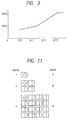
- An FLC display apparatus as a typical example of a display apparatus having a memory function has temperature dependency in drive conditions represented in Fig. 3.
- frame frequencies at 10°C, 25°C, and 40°C are 7 Hz, 10 Hz, and 20 Hz, respectively (number of scan lines: 1,024; drive voltage: 24 V; use of KMT-408 available from Nihon Chisso).
- flickering can be prevented by an 8 interlace scan at a low frequency, as proposed in the above prior-art invention.
- a screen discontinuation phenomenon of a display screen in a motion image display mode e.g., in a scroll display, which is the only drawback in the 8 interlace scan, can be reduced.
- a drive method varies depending on different display modes even when the temperature is kept unchanged. For example, an FLC display operated at 10 Hz in a display mode having 1,024 scan lines in Table 1 is changed to have 480 scan lines in a VGA mode, and the frame frequency is increased to 20 Hz or more.
- an FLC display is an X-Y matrix display
- the number of pixels cannot be changed in different display modes by a simple method such as changing the beam frequency.
- the number of physical pixels of an X-Y matrix display is determined uniquely during the manufacture and cannot be changed. For this reason, the number of logical pixels required in each display mode must be converted into the number of physical pixels.
- the gradation level number, and input information do not coincide with each other, for example, when the display has a monochrome 8-level display mode, while input information represents an RGB 256-level (each color component R, G, or B is represented by one of 256 levels) display mode, a relationship in color and gradation level number between the input information and the output information must be determined in a one-to-one correspondence with a display mode.
- the display When drive conditions of an FLC display are not satisfied, e.g., when an environmental temperature does not reach a temperature range of a display operation, the display sends a "wait" request to an image information generation side, so that the image information generation side waits before outputting image information.
- the display apparatus is reset or when a mode set before a reset operation is performed is to be immediately restored, various control and drive parameters and image information prior to the reset operation must be read out.
- the currently set display mode when the currently set display mode is to be changed, it is insufficient to set only a new mode. Assume that the VGA mode is currently set and that the currently set mode is to be changed to an EGA mode in response to an application software request.
- the previous display mode cannot be restored at the end of this application software if the various FLC display control parameters of the previous display mode are not saved in a given memory area.
- the previous image information must often be loaded in a memory.
- the FLC display control and drive parameters and original image data prior to its conversion to image data on the FLC display must be read by predetermined programming.
- a ROM (to be referred to as a ROM BIOS) for storing the necessary conditions of this product must be prepared.
- This ROM BIOS actually controls an interface associated with control and display of the computer side and the FLC side. The user can control display modes without having any specialized technical knowledge for controlling and driving an FLC display.
- a program in the ROM BIOS cannot continuously run.
- the program in the ROM BIOS cannot perform subsequent control while a display mode change request from the host CPU is received.
- the program in the ROM BIOS cannot control to transfer image information to the display panel. In this state, since the image information on the display panel cannot be updated, a CPU state cannot be monitored. Since the CPU side is reset to perform a restore operation, all the previously processed data are undesirably broken.
- the FLC display apparatus has temperature dependency in drive conditions, as shown in Fig. 3.
- frame frequencies at 10°C, 25°C, and 40°C are 7 Hz, 10 Hz, and 20 Hz, respectively (number of scan lines: 1,024; drive voltage: 24 V; use of KMT-408 available from Nihon Chisso).
- flickering can be prevented by an 8 interlace scan at a low frequency, as proposed in the above prior-art invention.
- a screen discontinuation phenomenon of a display screen in a motion image display mode e.g., in a scroll display, which is the only drawback in the 8 interlace scan, can be reduced.
- a drive method varies depending on different display modes even when the temperature is kept unchanged. For example, an FLC display operated at 10 Hz in a display mode having 1,024 scan lines in Table 1 in Fig. 7 is changed to have 480 scan lines in a VGA mode, and the frame frequency is increased to 20 Hz or more.
- a ROM (to be referred to as a ROM BIOS) for storing the necessary conditions of this product must be prepared.
- This ROM BIOS actually controls an interface associated with control and display of the computer side and the FLC side. The user can control display modes without having any specialized technical knowledge for controlling and driving an FLC display.
- a display control means for controlling a drive condition control means in accordance with a display mode stored in a display mode storing means includes a means for forcibly interrupting the display control, a means for restarting the display control in response to a signal from the drive-condition control means, and a means for setting a control interruption timing of the display control means at a predetermined arbitrary time.
- the display control means includes a means for controlling ON/OFF states of a drive element power source of the drive condition control means and a peripheral unit power source such as a back light required for a display element after the display control is interrupted.
- a display apparatus characterized by comprising:
- an FLC display apparatus serves as a display panel 2 (1,280 x 1,024 pixels).
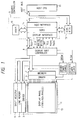
- a system in Fig. 1 includes display drivers 3 and 4, a display unit controller 8 for storing control programs of the present invention, a graphic controller 9 having a VRAM 10 serving as an image information storage memory, a host CPU 11 representing an IBM PC/AT, and a host bus 12.
- the system also includes a ROM BIOS 13 for storing an overall control monitor program as a characteristic feature of the present invention, a back light 13 serving as a back light source of the display panel 2, an invertor 14 for supplying a power to the back light 13, and a driver power source 15 for supplying a power to the display drivers 3 and 4.
- the host bus is an IBM standard interface hardware bus called an AT bus.
- a function defined in the ROM BIOS 13 is called from a video information generation side, i.e., the host CPU 11 side in accordance with a predetermined call rule.
- a parameter necessary for realizing a desired function is often transferred to the graphic controller 9.
- the function is translated by a GCPU (graphics control central processing unit) 14 for realizing the requested function, or the function signal is directly supplied to the display controller 9.
- GCPU graphics control central processing unit
- the graphic controller 9 transfers drive information and video information to the FLC display unit through the bidirectional data bus (PD0 - PD7). Since the drive information and the video information are transferred through the same transmission line, these pieces of information must be discriminated from each other.
- the discrimination signal AH/DL is used.
- the AH/DL signal is set at Hi level, information on the data bus (PD0 - PD7) represents "drive information”.
- the AH/DL signal is set at Lo level, information on the data bus (PD0 - PD7) represents "video information”.
- the FLC display unit controller 8 extracts the drive information from the video information with the drive information sent through the data bus (PD0 - PD7) and performs processing on the basis of the extracted drive information.
- the video information is sent to a shift register 6 on the information electrode drive circuit side in response to a transfer clock.
- the input and output devices must be synchronized at the time of display information transfer.
- the sync signals Hsync and Vsync are used.
- the Hsync signal is generated by the FLC display unit controller 8 every horizontal scan period
- the Vsync signal is generated by the FLC display unit controller 8 every vertical scan period during refreshing.
- the Hsync and Vsync signals are supplied to the graphic controller 9.
- the graphic controller 9 always monitors these sync signals.
- the graphic controller 9 transfers display information (i.e., drive information + video information). Otherwise, the graphic controller 9 waits until the next transfer enable signal is input at the end of each transfer cycle of display information.
- Fig. 4 is a basic communication timing chart obtained when display information is sent from the graphic controller 9 to the controller 8 of an FLC display unit 1. The basic communication will be described below.
- the controller 8 in the FLC display unit 1 sets the Hsync signal to Hi level during the display information transfer period.
- the controller 8 in the FLC display unit 1 sets the Hsync signal to Lo level again and is ready for receiving the next display information.
- Fig. 5 is a basic communication timing chart for reading out display information from the controller 8 of the FLC display unit 1 by the graphic controller 9. This basic communication will be described below.
- the graphic controller 9 sends to the controller 8 of the display unit 1 "information read request data" predetermined between the graphic controller 9 and the controller 8 of the FLC display unit 1 as drive information at timings of A0 to A15 in Fig. 5.
- the IH/OL signal is set at Hi level to set a data input mode.
- the data bus (PD0 - PD7) is set in a high-impedance state (Z) viewed from the graphic controller 9.
- the controller 8 in the FLC display unit 1 recognizes the "information read request data"
- it verifies that the IH/OL line is set at Hi level.
- Information is sent onto the data bus (PD0 - PD7), and the FLG signal is set at Hi level.
- the graphic controller 9 detects that the FLG line is set at Hi level, the concurrent data on the data bus (PD0 - PD7) is loaded and stored in the GCPU 14.
- display information is sent from the graphic controller 9 to the display, and the same communication operation as in Fig. 4 is performed.
- scan line address information serves as drive information.
- the drive information is sent onto A0 to A15 in Fig. 4 and is transferred to the display controller 8.
- the scan line address information is extracted by the controller 8 in the FLC display unit and is input to a scan line electrode drive circuit decoder 7 in synchronism with a timing for driving a designated scan line, thereby selecting a display-designated scan line.
- the video information is transferred to the information electrode drive circuit shift register 6 and is shifted by a transfer clock (CLK) in units of eight pixels.
- CLK transfer clock
- a series of communication operations described above are repeated to complete a write operation on the display panel and a partial write operation.
- Setup and updating of a display mode on the display apparatus are basically based on requests from the host side and basically comply with the timing chart of Fig. 6.
- the display mode can be changed and the display panel in each designated display mode can be driven in accordance with the above procedures.
- the controller 8 in the display unit 1 cannot detect a current display mode of the graphic controller 9. In this case, the controller 8 in the display unit 1 sends an INT signal to the graphic controller 9 and requests setup of a display mode.
- the graphic controller 9 receives the INT signal from the display unit controller 8, the graphic controller 9 sends display mode change request data to the display unit controller 8.
- the display apparatus sends an INT signal to the graphic controller 9 first.
- the graphic controller 9 Upon reception of the INT signal from the display apparatus, the graphic controller 9 sends display mode change data to the display unit controller 8.
- the subsequent operations are the same as the procedures as in generation of a request from the host apparatus, thereby performing read processing of the temperature information.
- a communication control line i.e., a signal line shown in (1)
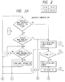
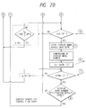
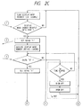
- a graphic controller control program in Fig. 2 is stored in the BIOS ROM 13.
- a display unit controller control program is stored in a memory element in the display unit controller 8.
- Numerals 1 to 8 in the handshake communication part in Fig. 2 correspond to the procedure numbers in "(4) Display Mode Setup".
- the display unit controller 8 receives a display mode number from the graphic controller 9 (this display mode number is not correct). The display unit controller 8 then waits until the IH/OL signal goes to "H" level. Meanwhile, after the graphic controller 9 sends image information, it verifies that the next Hsync signal is set at "L" level and sends the next image information. The graphic controller 9 repeats a loop B in Fig. 2.
- condition Tg ⁇ Td several 100 ms is established, the graphic controller 9 ends handshake communication when the Tg time elapses. Processing of the loop B is performed. For this reason, the graphic controller 9 can receive an INT signal from the display unit controller 8.
- the display unit controller 8 turns off the back light 13 in the display unit 1 and disables the display drivers 3 and 4.
- the display unit controller 8 then outputs an INT signal.
- the open state of the IH/OH signal line is returned to a normal state, a normal drive operation is restored. During this period, the driver power applied to the display panel 1 and the back light are kept off.
- the Tg and Td time setup operations are realized by software counters in the respective controllers. This may be, however, realized such that external hardware counters are arranged outside the GCPU 4 and the display unit controller 8, and set values of these counters may be controlled. At this time, signal lines for coincidence between the count values and the preset time counts are connected to the GCPU 4 and the display unit controller 8.
- the display apparatus sends an INT signal to the graphic controller 9 as in setup of the display mode.
- the graphic controller 9 checks the FLG line. If the FLG line is set at Hi level, the graphic controller 9 verifies that the INT signal represents a temperature information read request. Thereafter, the temperature information read operations and the scan mode setup operations are performed in the same manner as that upon generation of a request from the host side.
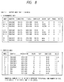
- Table 2 (Fig. 8) shows adapter names for supporting "1 Alphanumeric Mode 2" and "2 Graphics Mode” in the IBM mode, resolutions, colors, and the gradation level numbers, and FLC display drive information.
- a ratio "b/p” in Table 2 is used to determine the colors and gradation level numbers in the output information in response to the input information and represents the number of bits representing binary colors and binary gradation level information amount of each pixel (one logic pixel) in a video data format developed in the video image storage memory VRAM 10 in Fig. 1.
- An expression "ratio" in Table 2 represents a relationship between a physical pixel number and a logic pixel number. This relationship is shown in Fig. 11.
- the FLC display in this embodiment has physical pixels having two different area ratios as a pixel unit.
- the FLC display is basically a binary display, and a multivalue display by using this FLC display, i.e., a method of realizing multi-level display is proposed as a method using physical pixels having two different area ratios as one pixel unit).
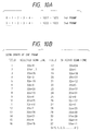
- the scan mode in Fig. 9 is designed to optimize prevention effects of the screen discontinuation phenomenon in the motion image display state and flickering depending on the frame frequency in accordance with the ratio and the environmental temperature of the display panel.
- Fig. 10 The specifications (scan order of the display panel) of the respective scan modes are shown in Fig. 10. A scan sequence in each scan mode will be briefly described below.
- the power sources for the display drivers 3 and 4 and the back light 13 can be controlled to be kept off. Therefore, a "burning" phenomenon can be prevented.
- Any one of the various display modes is used from the power-ON timing, and a systematic control method indispensable to change the display mode as needed is stored in the ROM.
- a control monitor unit capable of further changing the display mode from the host side, as needed, in accordance with a predetermined sequence is provided so that demand for supporting various display modes such as MultiSync display modes can be satisfied by using a ferroelectric liquid crystal display apparatus requiring drive information control which could not be performed by a conventional method due to different drive principles.
- the present invention is apparently effective for a display apparatus wherein scan and information signal electrodes are sandwiched between the matrix electrodes, and scan and information signals are applied to drive the apparatus having a memory function and temperature dependency in drive conditions.
- a display apparatus comprising:
Landscapes
- Engineering & Computer Science (AREA)
- Theoretical Computer Science (AREA)
- Physics & Mathematics (AREA)
- General Physics & Mathematics (AREA)
- Computer Hardware Design (AREA)
- Chemical & Material Sciences (AREA)
- Crystallography & Structural Chemistry (AREA)
- General Engineering & Computer Science (AREA)
- Human Computer Interaction (AREA)
- Liquid Crystal Display Device Control (AREA)
- Measuring Pulse, Heart Rate, Blood Pressure Or Blood Flow (AREA)
- Control Of Indicators Other Than Cathode Ray Tubes (AREA)
- Vehicle Body Suspensions (AREA)
- Diaphragms For Electromechanical Transducers (AREA)
- Preparation Of Compounds By Using Micro-Organisms (AREA)
- Compounds Of Unknown Constitution (AREA)
- Liquid Crystal (AREA)
Applications Claiming Priority (7)
| Application Number | Priority Date | Filing Date | Title |
|---|---|---|---|
| JP9141390A JP2728966B2 (ja) | 1990-04-06 | 1990-04-06 | 表示装置 |
| JP91413/90 | 1990-04-06 | ||
| JP9141390 | 1990-04-06 | ||
| JP9891590 | 1990-04-13 | ||
| JP2098915A JP2840374B2 (ja) | 1990-04-13 | 1990-04-13 | 表示制御装置 |
| JP98915/90 | 1990-04-13 | ||
| EP91105409A EP0450640B1 (de) | 1990-04-06 | 1991-04-05 | Anzeigegerät |
Related Parent Applications (2)
| Application Number | Title | Priority Date | Filing Date |
|---|---|---|---|
| EP91105409.6 Division | 1991-04-05 | ||
| EP91105409A Division EP0450640B1 (de) | 1990-04-06 | 1991-04-05 | Anzeigegerät |
Publications (3)
| Publication Number | Publication Date |
|---|---|
| EP0715293A2 true EP0715293A2 (de) | 1996-06-05 |
| EP0715293A3 EP0715293A3 (de) | 1996-07-31 |
| EP0715293B1 EP0715293B1 (de) | 1999-07-28 |
Family
ID=26432845
Family Applications (3)
| Application Number | Title | Priority Date | Filing Date |
|---|---|---|---|
| EP96100015A Expired - Lifetime EP0715294B1 (de) | 1990-04-06 | 1991-04-05 | Anzeigegerät |
| EP96100014A Expired - Lifetime EP0715293B1 (de) | 1990-04-06 | 1991-04-05 | Anzeigegerät |
| EP91105409A Expired - Lifetime EP0450640B1 (de) | 1990-04-06 | 1991-04-05 | Anzeigegerät |
Family Applications Before (1)
| Application Number | Title | Priority Date | Filing Date |
|---|---|---|---|
| EP96100015A Expired - Lifetime EP0715294B1 (de) | 1990-04-06 | 1991-04-05 | Anzeigegerät |
Family Applications After (1)
| Application Number | Title | Priority Date | Filing Date |
|---|---|---|---|
| EP91105409A Expired - Lifetime EP0450640B1 (de) | 1990-04-06 | 1991-04-05 | Anzeigegerät |
Country Status (6)
| Country | Link |
|---|---|
| US (1) | US5754153A (de) |
| EP (3) | EP0715294B1 (de) |
| KR (1) | KR940004138B1 (de) |
| AT (3) | ATE182711T1 (de) |
| DE (3) | DE69124407T2 (de) |
| ES (1) | ES2096597T3 (de) |
Families Citing this family (21)
| Publication number | Priority date | Publication date | Assignee | Title |
|---|---|---|---|---|
| JP2942092B2 (ja) * | 1993-04-20 | 1999-08-30 | キヤノン株式会社 | 液晶素子の制御方法 |
| JPH07160213A (ja) * | 1993-12-08 | 1995-06-23 | Canon Inc | 画像表示システム |
| JP2902290B2 (ja) * | 1994-01-11 | 1999-06-07 | キヤノン株式会社 | 表示制御システム |
| JP3281298B2 (ja) * | 1997-09-22 | 2002-05-13 | シャープ株式会社 | 液晶表示素子の駆動装置 |
| EP0994457B1 (de) * | 1998-10-12 | 2007-09-05 | Victor Company Of Japan, Limited | Signalverarbeitungsverfahren und Vorrichtung für Grauskala-Videosignal in einer Matrix-Anzeigevorrichtung |
| JP2000330526A (ja) | 1999-03-12 | 2000-11-30 | Minolta Co Ltd | 液晶表示装置、携帯電子機器及び駆動方法 |
| US6996623B1 (en) * | 1999-09-08 | 2006-02-07 | Matsushita Electric Industrial Co., Ltd. | Reception display apparatus and method for displaying screen partially with certain timing even when all data for the screen has not been received, and computer-readable record medium recording such reception display program |
| US6954195B2 (en) * | 2000-03-01 | 2005-10-11 | Minolta Co., Ltd. | Liquid crystal display device having a liquid crystal display driven by interlace scanning and/or sequential scanning |
| JP2002026801A (ja) * | 2000-07-05 | 2002-01-25 | Toshiba Corp | 無線通信端末 |
| JP4284857B2 (ja) * | 2000-11-06 | 2009-06-24 | コニカミノルタホールディングス株式会社 | 液晶表示装置 |
| US6870519B2 (en) | 2001-03-28 | 2005-03-22 | Intel Corporation | Methods for tiling multiple display elements to form a single display |
| JP3664102B2 (ja) * | 2001-06-05 | 2005-06-22 | セイコーエプソン株式会社 | 表示装置及びその信号処理方法 |
| KR20060000339A (ko) * | 2004-06-28 | 2006-01-06 | 삼성전자주식회사 | 디스플레이장치, 디스플레이 시스템 및 그 제어방법 |
| KR100755549B1 (ko) * | 2005-10-14 | 2007-09-06 | 비오이 하이디스 테크놀로지 주식회사 | 시분할순차구동방식의 액정표시장치 |
| TWI308309B (en) * | 2005-12-16 | 2009-04-01 | Delta Electronics Inc | Display device and mehtod for starting up at a low temperature |
| KR101246785B1 (ko) * | 2005-12-28 | 2013-04-03 | 엘지디스플레이 주식회사 | 스캐너 일체형 액정표시장치와 이의 스캐너 모드 구동방법 |
| US7903047B2 (en) * | 2006-04-17 | 2011-03-08 | Qualcomm Mems Technologies, Inc. | Mode indicator for interferometric modulator displays |
| TWI331741B (en) * | 2006-10-14 | 2010-10-11 | Au Optronics Corp | System and driving method for color sequencial liquid crystal display (lcd) |
| KR101830679B1 (ko) * | 2010-07-29 | 2018-02-22 | 삼성디스플레이 주식회사 | 표시 패널 검사 장치 및 그 방법 |
| US20130314618A1 (en) * | 2011-02-08 | 2013-11-28 | Sharp Kabushiki Kaisha | Method of driving display device, driving device of display device, and television device |
| US11246905B2 (en) | 2016-08-15 | 2022-02-15 | President And Fellows Of Harvard College | Treating infections using IdsD from Proteus mirabilis |
Family Cites Families (22)
| Publication number | Priority date | Publication date | Assignee | Title |
|---|---|---|---|---|
| US4119842A (en) * | 1977-06-17 | 1978-10-10 | General Motors Corporation | Heater control system for liquid crystal device |
| US4655561A (en) * | 1983-04-19 | 1987-04-07 | Canon Kabushiki Kaisha | Method of driving optical modulation device using ferroelectric liquid crystal |
| US4665501A (en) * | 1983-09-30 | 1987-05-12 | Esprit Systems, Inc. | Workstation for local and remote data processing |
| AU584867B2 (en) * | 1983-12-09 | 1989-06-08 | Seiko Instruments & Electronics Ltd. | A liquid crystal display device |
| DE3508321A1 (de) * | 1985-03-06 | 1986-09-11 | CREATEC Gesellschaft für Elektrotechnik mbH, 1000 Berlin | Programmierbare schaltung zur steuerung einer fluessigkristallanzeige |
| FR2581209B1 (fr) * | 1985-04-26 | 1993-11-05 | Canon Kk | Dispositif optique a cristal liquide |
| EP0236111A3 (de) * | 1986-03-03 | 1989-07-19 | Seiko Instruments Inc. | Schnittstelle für eine dünne Farbanzeigetafel |
| EP0261896B1 (de) * | 1986-09-20 | 1993-05-12 | THORN EMI plc | Anzeigevorrichtung |
| US4803476A (en) * | 1986-10-24 | 1989-02-07 | Visual Technology Incorporated | Video terminal for use in graphics and alphanumeric applications |
| US4952032A (en) * | 1987-03-31 | 1990-08-28 | Canon Kabushiki Kaisha | Display device |
| DE3850520T2 (de) * | 1987-03-31 | 1994-12-01 | Canon Kk | Anzeigevorrichtung. |
| US5041821A (en) * | 1987-04-03 | 1991-08-20 | Canon Kabushiki Kaisha | Ferroelectric liquid crystal apparatus with temperature dependent DC offset voltage |
| EP0287055B1 (de) * | 1987-04-15 | 1993-09-29 | Sharp Kabushiki Kaisha | Flüssigkristallanzeigegerät |
| EP0295691B1 (de) * | 1987-06-19 | 1994-11-23 | Kabushiki Kaisha Toshiba | Anzeigemodusumschaltsystem für ein Plasmaanzeigegerät |
| DE3852215T2 (de) * | 1987-06-19 | 1995-04-06 | Toshiba Kawasaki Kk | System zum Steuern der Anzeigezone für ein Plasmaanzeigegerät. |
| GB2207272B (en) * | 1987-07-18 | 1991-08-14 | Stc Plc | Addressing liquid crystal cells |
| US5049865A (en) * | 1987-10-29 | 1991-09-17 | Nec Corporation | Display apparatus |
| DE3856474T2 (de) * | 1987-11-12 | 2001-11-08 | Canon K.K., Tokio/Tokyo | Flüssigkristallgerät |
| CA1319767C (en) * | 1987-11-26 | 1993-06-29 | Canon Kabushiki Kaisha | Display apparatus |
| ATE121211T1 (de) * | 1988-08-17 | 1995-04-15 | Canon Kk | Anzeigevorrichtung. |
| JP2909079B2 (ja) * | 1988-09-13 | 1999-06-23 | 株式会社東芝 | 表示制御方式 |
| JP3126360B2 (ja) * | 1989-09-01 | 2001-01-22 | キヤノン株式会社 | 表示システム及びその表示制御方法 |
-
1991
- 1991-04-04 KR KR91005464A patent/KR940004138B1/ko not_active Expired - Fee Related
- 1991-04-05 ES ES91105409T patent/ES2096597T3/es not_active Expired - Lifetime
- 1991-04-05 DE DE69124407T patent/DE69124407T2/de not_active Expired - Fee Related
- 1991-04-05 EP EP96100015A patent/EP0715294B1/de not_active Expired - Lifetime
- 1991-04-05 EP EP96100014A patent/EP0715293B1/de not_active Expired - Lifetime
- 1991-04-05 AT AT96100014T patent/ATE182711T1/de not_active IP Right Cessation
- 1991-04-05 EP EP91105409A patent/EP0450640B1/de not_active Expired - Lifetime
- 1991-04-05 AT AT96100015T patent/ATE183842T1/de not_active IP Right Cessation
- 1991-04-05 AT AT91105409T patent/ATE148575T1/de not_active IP Right Cessation
- 1991-04-05 DE DE69131558T patent/DE69131558T2/de not_active Expired - Fee Related
- 1991-04-05 DE DE69131492T patent/DE69131492T2/de not_active Expired - Fee Related
-
1995
- 1995-04-06 US US08/417,846 patent/US5754153A/en not_active Expired - Lifetime
Also Published As
| Publication number | Publication date |
|---|---|
| EP0450640B1 (de) | 1997-01-29 |
| EP0715293A3 (de) | 1996-07-31 |
| ATE183842T1 (de) | 1999-09-15 |
| US5754153A (en) | 1998-05-19 |
| KR940004138B1 (en) | 1994-05-13 |
| DE69124407D1 (de) | 1997-03-13 |
| EP0450640A3 (en) | 1992-11-19 |
| EP0715294A3 (de) | 1996-08-07 |
| EP0715294A2 (de) | 1996-06-05 |
| EP0715294B1 (de) | 1999-08-25 |
| DE69131558T2 (de) | 2000-04-13 |
| DE69131558D1 (de) | 1999-09-30 |
| EP0715293B1 (de) | 1999-07-28 |
| DE69124407T2 (de) | 1997-06-26 |
| ATE148575T1 (de) | 1997-02-15 |
| ES2096597T3 (es) | 1997-03-16 |
| DE69131492D1 (de) | 1999-09-02 |
| EP0450640A2 (de) | 1991-10-09 |
| ATE182711T1 (de) | 1999-08-15 |
| KR910018964A (ko) | 1991-11-30 |
| DE69131492T2 (de) | 2000-04-13 |
Similar Documents
| Publication | Publication Date | Title |
|---|---|---|
| EP0715293B1 (de) | Anzeigegerät | |
| US5784037A (en) | Display system | |
| US5805149A (en) | Display control device and display apparatus with display control device | |
| EP0295689B1 (de) | Anzeigesteuergerät für eine Kathodenstrahlröhre-/Plasmaanzeigeeinheit | |
| EP0526097A2 (de) | Anzeigegerät | |
| US6198469B1 (en) | “Frame-rate modulation method and apparatus to generate flexible grayscale shading for super twisted nematic displays using stored brightness-level waveforms” | |
| JP2009181139A (ja) | フラットパネル表示装置及びその駆動方法 | |
| US5508714A (en) | Display control apparatus for converting CRT resolution into PDP resolution by hardware | |
| JPH08263022A (ja) | 節電機能を具備する液晶表示装置駆動回路 | |
| US5606336A (en) | Display control apparatus | |
| US5475808A (en) | Display control apparatus | |
| JP2840374B2 (ja) | 表示制御装置 | |
| EP0729129B1 (de) | Anzeigesystem und -verfahren mit einer Bildumwandlung, die ohne visuelle Inspektion kontrolliert werden kann | |
| US20010009419A1 (en) | Image data displaying system, image drawing apparatus, image drawing method and image drawing program | |
| US5757352A (en) | Image information control apparatus and display device | |
| EP1538595B1 (de) | Ansteuerschaltkreis für eine Flüssigkristallanzeige und Ansteuerverfahren dafür | |
| US6239775B1 (en) | Driving circuit of plasma display panel | |
| EP0462541B1 (de) | Bildinformationssteuergerät und Anzeigesystem | |
| JP2728966B2 (ja) | 表示装置 | |
| JPH11231847A (ja) | 液晶ディスプレイ・コントローラ | |
| EP0519743B1 (de) | Bildinformationssteuergerät und Anzeigesystem | |
| US6448961B2 (en) | Driving circuit of plasma display panel | |
| JPH08334739A (ja) | 表示装置及びその表示制御装置及び情報処理装置 |
Legal Events
| Date | Code | Title | Description |
|---|---|---|---|
| PUAI | Public reference made under article 153(3) epc to a published international application that has entered the european phase |
Free format text: ORIGINAL CODE: 0009012 |
|
| AC | Divisional application: reference to earlier application |
Ref document number: 450640 Country of ref document: EP |
|
| AK | Designated contracting states |
Kind code of ref document: A2 Designated state(s): AT BE CH DE DK ES FR GB GR IT LI LU NL SE |
|
| PUAL | Search report despatched |
Free format text: ORIGINAL CODE: 0009013 |
|
| AK | Designated contracting states |
Kind code of ref document: A3 Designated state(s): AT BE CH DE DK ES FR GB GR IT LI LU NL SE |
|
| 17P | Request for examination filed |
Effective date: 19961217 |
|
| 17Q | First examination report despatched |
Effective date: 19980430 |
|
| GRAG | Despatch of communication of intention to grant |
Free format text: ORIGINAL CODE: EPIDOS AGRA |
|
| GRAG | Despatch of communication of intention to grant |
Free format text: ORIGINAL CODE: EPIDOS AGRA |
|
| GRAH | Despatch of communication of intention to grant a patent |
Free format text: ORIGINAL CODE: EPIDOS IGRA |
|
| GRAH | Despatch of communication of intention to grant a patent |
Free format text: ORIGINAL CODE: EPIDOS IGRA |
|
| GRAA | (expected) grant |
Free format text: ORIGINAL CODE: 0009210 |
|
| AC | Divisional application: reference to earlier application |
Ref document number: 450640 Country of ref document: EP |
|
| AK | Designated contracting states |
Kind code of ref document: B1 Designated state(s): AT BE CH DE DK ES FR GB GR IT LI LU NL SE |
|
| PG25 | Lapsed in a contracting state [announced via postgrant information from national office to epo] |
Ref country code: SE Free format text: THE PATENT HAS BEEN ANNULLED BY A DECISION OF A NATIONAL AUTHORITY Effective date: 19990728 Ref country code: NL Free format text: LAPSE BECAUSE OF FAILURE TO SUBMIT A TRANSLATION OF THE DESCRIPTION OR TO PAY THE FEE WITHIN THE PRESCRIBED TIME-LIMIT Effective date: 19990728 Ref country code: LI Free format text: LAPSE BECAUSE OF FAILURE TO SUBMIT A TRANSLATION OF THE DESCRIPTION OR TO PAY THE FEE WITHIN THE PRESCRIBED TIME-LIMIT Effective date: 19990728 Ref country code: IT Free format text: LAPSE BECAUSE OF FAILURE TO SUBMIT A TRANSLATION OF THE DESCRIPTION OR TO PAY THE FEE WITHIN THE PRESCRIBED TIME-LIMIT;WARNING: LAPSES OF ITALIAN PATENTS WITH EFFECTIVE DATE BEFORE 2007 MAY HAVE OCCURRED AT ANY TIME BEFORE 2007. THE CORRECT EFFECTIVE DATE MAY BE DIFFERENT FROM THE ONE RECORDED. Effective date: 19990728 Ref country code: GR Free format text: LAPSE BECAUSE OF NON-PAYMENT OF DUE FEES Effective date: 19990728 Ref country code: ES Free format text: THE PATENT HAS BEEN ANNULLED BY A DECISION OF A NATIONAL AUTHORITY Effective date: 19990728 Ref country code: CH Free format text: LAPSE BECAUSE OF FAILURE TO SUBMIT A TRANSLATION OF THE DESCRIPTION OR TO PAY THE FEE WITHIN THE PRESCRIBED TIME-LIMIT Effective date: 19990728 Ref country code: BE Free format text: LAPSE BECAUSE OF FAILURE TO SUBMIT A TRANSLATION OF THE DESCRIPTION OR TO PAY THE FEE WITHIN THE PRESCRIBED TIME-LIMIT Effective date: 19990728 Ref country code: AT Free format text: LAPSE BECAUSE OF FAILURE TO SUBMIT A TRANSLATION OF THE DESCRIPTION OR TO PAY THE FEE WITHIN THE PRESCRIBED TIME-LIMIT Effective date: 19990728 |
|
| REF | Corresponds to: |
Ref document number: 182711 Country of ref document: AT Date of ref document: 19990815 Kind code of ref document: T |
|
| REG | Reference to a national code |
Ref country code: CH Ref legal event code: EP |
|
| REF | Corresponds to: |
Ref document number: 69131492 Country of ref document: DE Date of ref document: 19990902 |
|
| ET | Fr: translation filed | ||
| PG25 | Lapsed in a contracting state [announced via postgrant information from national office to epo] |
Ref country code: DK Free format text: LAPSE BECAUSE OF FAILURE TO SUBMIT A TRANSLATION OF THE DESCRIPTION OR TO PAY THE FEE WITHIN THE PRESCRIBED TIME-LIMIT Effective date: 19991028 |
|
| NLV1 | Nl: lapsed or annulled due to failure to fulfill the requirements of art. 29p and 29m of the patents act | ||
| REG | Reference to a national code |
Ref country code: CH Ref legal event code: PL |
|
| PG25 | Lapsed in a contracting state [announced via postgrant information from national office to epo] |
Ref country code: LU Free format text: LAPSE BECAUSE OF NON-PAYMENT OF DUE FEES Effective date: 20000405 |
|
| PLBE | No opposition filed within time limit |
Free format text: ORIGINAL CODE: 0009261 |
|
| STAA | Information on the status of an ep patent application or granted ep patent |
Free format text: STATUS: NO OPPOSITION FILED WITHIN TIME LIMIT |
|
| 26N | No opposition filed | ||
| REG | Reference to a national code |
Ref country code: GB Ref legal event code: IF02 |
|
| PGFP | Annual fee paid to national office [announced via postgrant information from national office to epo] |
Ref country code: GB Payment date: 20030402 Year of fee payment: 13 |
|
| PGFP | Annual fee paid to national office [announced via postgrant information from national office to epo] |
Ref country code: FR Payment date: 20030408 Year of fee payment: 13 |
|
| PGFP | Annual fee paid to national office [announced via postgrant information from national office to epo] |
Ref country code: DE Payment date: 20030417 Year of fee payment: 13 |
|
| PG25 | Lapsed in a contracting state [announced via postgrant information from national office to epo] |
Ref country code: GB Free format text: LAPSE BECAUSE OF NON-PAYMENT OF DUE FEES Effective date: 20040405 |
|
| PG25 | Lapsed in a contracting state [announced via postgrant information from national office to epo] |
Ref country code: DE Free format text: LAPSE BECAUSE OF NON-PAYMENT OF DUE FEES Effective date: 20041103 |
|
| GBPC | Gb: european patent ceased through non-payment of renewal fee | ||
| PG25 | Lapsed in a contracting state [announced via postgrant information from national office to epo] |
Ref country code: FR Free format text: LAPSE BECAUSE OF NON-PAYMENT OF DUE FEES Effective date: 20041231 |
|
| REG | Reference to a national code |
Ref country code: FR Ref legal event code: ST |