EP0715452A2 - Mehrkanaliges Druckverfahren und -gerät in einem Rasterausgabeabtastsystem - Google Patents
Mehrkanaliges Druckverfahren und -gerät in einem Rasterausgabeabtastsystem Download PDFInfo
- Publication number
- EP0715452A2 EP0715452A2 EP95308692A EP95308692A EP0715452A2 EP 0715452 A2 EP0715452 A2 EP 0715452A2 EP 95308692 A EP95308692 A EP 95308692A EP 95308692 A EP95308692 A EP 95308692A EP 0715452 A2 EP0715452 A2 EP 0715452A2
- Authority
- EP
- European Patent Office
- Prior art keywords
- light beams
- optical
- scanning system
- raster output
- polygon
- Prior art date
- Legal status (The legal status is an assumption and is not a legal conclusion. Google has not performed a legal analysis and makes no representation as to the accuracy of the status listed.)
- Withdrawn
Links
- 238000000034 method Methods 0.000 title description 9
- 230000003287 optical effect Effects 0.000 claims abstract description 71
- 108091008695 photoreceptors Proteins 0.000 claims abstract description 9
- 230000010287 polarization Effects 0.000 claims description 7
- 238000003384 imaging method Methods 0.000 claims description 5
- 239000003086 colorant Substances 0.000 description 5
- 235000021438 curry Nutrition 0.000 description 3
- 238000000926 separation method Methods 0.000 description 1
- 239000000758 substrate Substances 0.000 description 1
Images



Classifications
-
- H—ELECTRICITY
- H04—ELECTRIC COMMUNICATION TECHNIQUE
- H04N—PICTORIAL COMMUNICATION, e.g. TELEVISION
- H04N1/00—Scanning, transmission or reproduction of documents or the like, e.g. facsimile transmission; Details thereof
- H04N1/46—Colour picture communication systems
- H04N1/50—Picture reproducers
- H04N1/506—Reproducing the colour component signals picture-sequentially, e.g. with reproducing heads spaced apart from one another in the subscanning direction
Definitions
- the present invention relates to xerographic printing devices utilizing a raster output scanner to generate scanning light beams, and in particular to such printing devices that utilize a plurality of input optical channels.
- Flying spot scanners often referred to as raster output scanners (ROS)
- ROS raster output scanners
- a reflective multi-faceted polygon mirror that is rotated about its central axis to repeatedly sweep one or more intensity modulated beams of light across a photosensitive recording medium in a line scanning direction (also known as the fast-scan direction) while the recording medium is being advanced in an orthogonal, or process, direction (also known as the slow-scan direction) such that the beams scan the recording medium in accordance with a raster scanning pattern.
- Digital printing is performed by serially intensity modulating each of the beams in accordance with a binary sample string, whereby the recording medium is exposed to the image represented by the samples as it is being scanned.
- Printers that sweep several beams simultaneously are referred to as multi-beam printers. Both ROS and multi-beam printer techniques are illustrated in US-A-4,474,422 to Kitamura.
- Kitamura patent multiple lasers are arranged diagonally to sweep multiple beams across a single photoreceptor.
- the beams are also displaced from each other in the cross-scan direction so that multiple lines can be scanned simultaneously across the photoreceptor.
- An object of the Kitamura patent is to reduce variations in pitch by spacing individual lasers within the laser array closely in a compact structure.
- High speed process color and multi-highlight color xerographic image output terminals often require multiple independently addressable raster lines to be printed simultaneously at separate locations. This is called multi-station printing.
- US-A-5,233,367 discloses an image forming apparatus and method for interlace scanning plural light beams by deflecting the plural light beams with a rotating polygon.
- the spacing between adjacent beams on the recording medium is defined by an interlace factor and may be adjusted to a desired interlace factor.
- US-A-4,761,046 to Funato discloses a method of recording a color image on a recording medium by applying a plurality of laser beam signals simultaneously to a plurality of photosensitive bodies to form latent images thereon.
- the method of Funato applies the modulated laser beams to a hologram disk having a circular transparent substrate in a plurality of optically equivalent hologram gradings.
- the hologram disk rotates to deflect the laser beam via optics onto the photosensitive bodies.
- Problems with the Funato method include the high cost of producing the hologram and the difficulty of properly registering system colors.
- US-A-4,578,688 to Okuno discloses a light beam printer which directs first and second light beams onto separate facets of a rotating polygon mirror.
- the rotating polygon mirror directs a first beam and a second beam through separate optics onto first and second photosensitive means, respectively.
- the first and second laser beams each correspond to a separate color image signal and thus form images on the first and second photosensitive mediums, each of a different color.
- the images are then transferred onto a transfer medium in superposed relationship with each other to form a two color image.
- the system of Okuno is thus only capable of forming a two color image in a single pass of the transfer medium by the photosensitive mediums.
- US-A-4,591,903 to Kawamura et al. discloses a recording apparatus which scans four laser beams onto four separate photoreceptors.
- the apparatus uses two separate rotating polygon mirrors to deflect the beams.
- Two laser beams are directed to separate facets of each of the two rotating polygons, which deflect the laser beams through optics onto the separate photoreceptors.
- the laser beams scan images of one of four separate colors onto each of the photosensitive drums.
- the apparatus then transfers the images to a recording sheet.
- the apparatus of Kawamura et al. is thus capable of producing a four color image with a single pass of the recording sheet past the photosensitive drums. Problems with this apparatus include the high cost of providing multiple, nearly identical ROSs with multiple rotating polygon mirrors and the difficulty of registering system colors.
- a raster output scanner for a printing device includes a deflector having a plurality of facets, a plurality of input optical channels, each of the input optical channels directing at least one of a plurality of light beams onto separate facets of the deflector, the deflector deflecting the light beams onto disparate optical paths and an optical system located on the disparate optical paths, the optical system directing at least one of the light beams onto each of first, second, third and fourth image receiving locations.
- the deflector may be a polygon mirror mounted for rotation about a central horizontal axis.
- the image receiving locations are disposed on first, second, third and fourth photoreceptors.
- the invention thus enables the provision of a multiple light beam ROS system that provides one pass four color printing utilizing a single rotating polygon deflector.
- the invention provides such a multiple light beam ROS system that utilizes multiple input optical channels, and multiple output optical channels.
- the multiple light beam ROS system that directs multiple light beams to each of a plurality of image receiving locations.
- Embodiments of the invention are applicable to all types of printing devices. Such printing devices include facsimile machines, copiers, printers, etc.
- the illustrated embodiments direct each light beam to separate image receiving locations that are located on separate photoconductive drums.
- embodiments of the invention are also applicable to printing devices that use a single image receiving location such as an endless belt to receive multiple scanned light beams.
- an embodiment of the invention has a plurality of light source devices 12 that output four separate light beams 14, 16, 18 and 20. While it appears that there only two light source devices 12 in Fig. 1b there are actually four such light source devices 12, which are sagittally displaced (displaced parallel to the axis of rotation A of polygon 22). Thus, only two of the four light source devices 12 are visible in Fig. 1b. Similarly, the light beams 14 and 16 and the light beams 18 and 20 are sagittally displaced and thus appear as a single light beam in Fig. 1b.
- the light beams 14, 16, 18 and 20 are directed through separate input optics 26, which direct the beams 14, 16, 18 and 20 to the rotating polygon 22.
- four separate input optical channels direct the light beams 14, 16, 18 and 20 respectively to appropriate facets 24 of the polygon 22.
- Each of the input optical channels includes at least one light beam which passes through a single input optics 26.
- the raster output scanning system of the embodiment shown in Figs. 1a and 1b has four input optical channels which are sagittally separated.
- the light beams 14, 16, 18 and 20 are deflected by the rotating polygon 22 through imaging and correction optics (e.g., including an F ⁇ scan lens) 28, which focuses the beams and corrects for errors such as polygon angle error and wobble.
- imaging and correction optics e.g., including an F ⁇ scan lens
- the light beams 14, 16, 18 and 20 are then reflected by mirrors 30 and are scanned across image receiving locations 32, 34, 36 and 38 to form images on the image receiving locations.
- the mirrors 30 are positioned to equalize an optical path length of each of the light beams 14, 16, 18 and 20.
- An optical output channel includes at least one light beam and a single imaging and correction optics 28.
- the system shown in Figs. 1a and 1b has four output optical channels with one of the light beams 14, 16, 18 and 20 output through each of the output optical channels.
- Each of the light beams 14, 16, 18 and 20 when scanned across its associated image receiving location 32, 34, 36 or 38 forms an image of one of a plurality of different colors.
- Each of the images is transferred from the image receiving locations 32, 34, 36 and 38 onto a transfer medium (not shown) such as a sheet of paper, to form a color image thereon.
- a transfer medium such as a sheet of paper
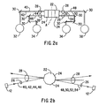
- the ROS system shown in Figs. 2a and 2b is similar to the one shown in Figs. 1a and 1b except that the system uses eight light beams 40, 42, 44, 46, 48, 50, 52 and 54.
- the ROS system shown in Figs. 2a and 2b has four input optical channels and four output optical channels.
- the ROS system shown in Figs. 2a and 2b has two light beams directed by each of the input optical channels to the rotating polygon 22.
- Each of the output optical channels directs two of the light beams onto one of the image receiving locations 32, 34, 36 and 38.
- the ROS system of this embodiment produces greater throughput than the ROS system illustrated in Figs. 1a and 1b.
- the ROS system of Figs. 2a and 2b could alternatively operate with more than two beams per optical channel to further increase throughput of the ROS system.
- the ROS system of Figs. 2a and 2b directs two (or more) beams to each of the image receiving locations 32, 34, 36 and 38.
- the beams directed to each of the image receiving locations 32, 34, 36 and 38 are sagitally separated and are either in pitch with each other or, alternatively, may be interlaced, as described in US-A-5,233,367 to Curry.
- the ROS scanning system shown in Figs. 3a and 3b is similar to the ROS scanning system shown in Figs. 1a through 2b except that the ROS scanning system shown in Figs. 3a and 3b includes two input optical channels and two output optical channels.
- each of the light source devices 12 outputs two of the four light beams 56, 58, 60 and 62.
- the light beams output from each of the light source devices 12 are sagittally separated.
- the laser beams output from each of the laser source devices have either a different wavelength from each other or a different polarization from each other. Because this embodiment has only two optical output channels, the light beams on each optical output channel are closely spaced.
- the light beams 56 and 58 and the light beams 60 and 62 are directed to the optical separators 64.
- the optical separators 64 can be dichroic mirrors, (e.g., colorselective beam splitters) comprised of a wavelength selective, multilayer film, where the beams have different wavelengths, or alternatively, the optical separators 64 may be polarized beam separators which can be, for example, prisms or devices having a polarization selective multiple layer film. Similar to the previously described embodiments, the embodiment illustrated in Figs. 3a and 3b utilizes a plurality of input optical channels to direct light beams to separate facets of a single rotating polygon to produce a four-color image in a single pass of an imaging medium past the image receiving locations 32, 34, 36 and 38.
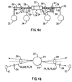
- the ROS scanning system illustrated in Figs. 4a and 4b is similar to the ROS scanning system illustrated in Figs. 3a and 3b except that the ROS system of Figs. 4a and 4b has four light beams for each input optical channel and four light beams for each output optical channel.
- each of the two light source devices 12 outputs four light beams through a single input optical channel to the rotating polygon deflector 22.
- Two of the four light beams output from each of the laser source devices 12 have either a different wavelength or a different polarization from the other two light beams.
- each of the optical separators 64 pass two of the four light beams and reflect two of the four light beams, so that two of the light beams are directed to each of the image receiving locations 32, 34, 36 and 38.
- the ROS system of Figs. 4a and 4b by directing two light beams to each of the image receiving locations 32, 34, 36 and 38 has a higher throughput than the ROS scanning system shown in Figs. 3a and 3b.
- an increased number of light beams could be directed to each of the image receiving locations 32, 34, 36 and 38.
- the ROS system shown in Figs. 4a and 4b utilizes a plurality of input optical channels to direct light beams to separate facets of a single rotating polygon to produce a four color image with one pass of a recording medium past the image receiving locations 32, 34, 36 and 38.
- the ROS system of Figs. 4a and 4b directs two (or more) beams (66,68; 70,72; 74,76; 78,80) to each of the image receiving locations 32, 34, 36 and 38.
- the beams directed to each of the image receiving locations 32, 34, 36 and 38 are sagitally separated and are either in pitch with each other or, alternatively, may be interlaced, as described in US-A-5,233,367 to Curry.
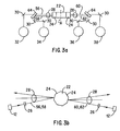
- the embodiment illustrated in Figs. 5a and 5b is similar to the embodiment illustrated in Figs. 3a and 3b, except that the embodiment illustrated in Fig. 5a and 5b includes four light source devices 12 and 12' and four input optical channels which include four light beams 82, 84, 86 and 88.
- the light beams 82, 84, 86 and 88 are directed through input optics 26 or 26' to the rotating polygon 22, with two of the four light beams 82, 84, 86 and 88 hitting separate facets of the rotating polygon 22.
- this embodiment includes two output optical channels each directing two light beams to the optical separators 64.
- the light beams 82, 84, 86 and 88 appear in Fig. 5a to be sagittally separated, the light beams in actuality are only tangentially separated, as shown in Fig. 5b, and are illustrated this way in Fig. 5a for illustration purposes only.
- the light beams 82 and 84 between the rotating polygon and each of the optical separators 64 would appear from the side view of Fig. 5a as a single light beam because the beams from this angle overlap one another when tangentially separated without sagittal separation.
- the ROS system shown in Figs. 5a and 5b utilizes a plurality of input optical channels to direct light beams to separate facets of a single rotating polygon to produce a four color image with one pass of a recording medium past the image receiving locations 32, 34, 36 and 38.
- each of the light source devices 12 and 12' output two of eight light beams 90, 92, 94, 96, 98, 100, 102, and 104.
- the light beams 90 and 92 are separated from the light beams 94 and 96 in the tangential direction only (they share a common sagittal plane).
- the light beams 98, 100, 102 and 104 are also separated tangentially (they share a common sagittal plane). While the light beams 90, 92, 94, 96, 98, 100, 102 and 104 appear in Fig.
- the light beams 90 and 92 have either a different wavelength or a different polarization from the light beams 94 and 96.
- the light beams 98 and 100 have either a different wavelength or a different polarization from the light beams 102 and 104. This is necessary so that each of the optical separators 64 may separate by passing or reflecting two of the light beams 90, 92, 94, and 96, and two of the light beams 98, 100, 102 and 104 to each of the image receiving locations 32, 34, 36 and 38.
- the ROS scanning system illustrated in Figs. 6a and 6b due to the fact that it directs two light beams to each of the image receiving locations 32, 34, 36 and 38, has a higher throughput than the ROS system illustrated in Figs. 5a and 5b.
- the ROS system illustrated in Figs. 6a and 6b may be modified so as to direct more than two light beams to each of the image receiving locations 32, 34, 36 and 38, for an even greater throughput.
- the embodiment illustrated in Figs. 6a and 6b utilizes a plurality of input optical channels to direct light beams to separate facets of a single rotating polygon to produce a four color image with a single pass of a imaging medium past the image receiving locations 32, 34, 36 and 38.
- the ROS system of Figs. 6a and 6b directs two (or more) beams to each of the image receiving locations 32, 34, 36 and 38.
- the beams directed to each of the image receiving locations 32, 34, 36 and 38 are sagitally separated and are either in pitch with each other or, alternatively, may be interlaced, as described in US-A-5,233,367 to Curry.
Landscapes
- Engineering & Computer Science (AREA)
- Multimedia (AREA)
- Signal Processing (AREA)
- Mechanical Optical Scanning Systems (AREA)
- Facsimile Scanning Arrangements (AREA)
- Color Electrophotography (AREA)
- Color, Gradation (AREA)
- Laser Beam Printer (AREA)
- Exposure Or Original Feeding In Electrophotography (AREA)
Applications Claiming Priority (2)
| Application Number | Priority Date | Filing Date | Title |
|---|---|---|---|
| US352766 | 1994-12-02 | ||
| US08/352,766 US5691761A (en) | 1994-12-02 | 1994-12-02 | Method and apparatus for multi-channel printing in a raster output scanning system |
Publications (2)
| Publication Number | Publication Date |
|---|---|
| EP0715452A2 true EP0715452A2 (de) | 1996-06-05 |
| EP0715452A3 EP0715452A3 (de) | 1997-11-19 |
Family
ID=23386411
Family Applications (1)
| Application Number | Title | Priority Date | Filing Date |
|---|---|---|---|
| EP95308692A Withdrawn EP0715452A3 (de) | 1994-12-02 | 1995-12-01 | Mehrkanaliges Druckverfahren und -gerät in einem Rasterausgabeabtastsystem |
Country Status (3)
| Country | Link |
|---|---|
| US (1) | US5691761A (de) |
| EP (1) | EP0715452A3 (de) |
| JP (1) | JPH08227050A (de) |
Families Citing this family (11)
| Publication number | Priority date | Publication date | Assignee | Title |
|---|---|---|---|---|
| JP3990008B2 (ja) * | 1997-10-20 | 2007-10-10 | コニカミノルタビジネステクノロジーズ株式会社 | マルチビーム走査装置 |
| KR100311004B1 (ko) * | 1998-02-16 | 2002-02-19 | 윤종용 | 전자사진방식칼라인쇄기의빔주사장치 |
| JP2001051217A (ja) * | 1999-08-06 | 2001-02-23 | Matsushita Electric Ind Co Ltd | ビーム走査光学装置 |
| KR100452852B1 (ko) * | 2002-01-09 | 2004-10-14 | 삼성전자주식회사 | 확대 광학계 및 그것을 갖는 화상형성 장치 |
| KR100846775B1 (ko) * | 2002-05-10 | 2008-07-16 | 삼성전자주식회사 | 칼라 레이저 프린터 |
| US6774923B2 (en) | 2002-05-31 | 2004-08-10 | Lexmark International, Inc. | Dual polygon laser printhead for a color printer |
| KR100815363B1 (ko) * | 2004-10-13 | 2008-03-19 | 삼성전기주식회사 | 컬러 레이저 프린터용 광학계 |
| JP4955267B2 (ja) * | 2005-12-22 | 2012-06-20 | 株式会社リコー | マルチビーム走査装置及び画像形成装置 |
| JP5022945B2 (ja) * | 2008-02-29 | 2012-09-12 | 株式会社リコー | 光書込装置及び画像形成装置 |
| WO2011061824A1 (ja) * | 2009-11-18 | 2011-05-26 | キヤノン株式会社 | 光走査装置 |
| JP5691633B2 (ja) * | 2010-06-25 | 2015-04-01 | 株式会社リコー | 光走査装置及び画像形成装置 |
Citations (8)
| Publication number | Priority date | Publication date | Assignee | Title |
|---|---|---|---|---|
| US4474422A (en) | 1979-11-13 | 1984-10-02 | Canon Kabushiki Kaisha | Optical scanning apparatus having an array of light sources |
| US4578688A (en) | 1983-04-12 | 1986-03-25 | Canon Kabushiki Kaisha | Light beam printer |
| US4591903A (en) | 1981-12-01 | 1986-05-27 | Canon Kabushiki Kaisha | Recording apparatus |
| US4761046A (en) | 1985-05-02 | 1988-08-02 | Ricoh Company, Ltd. | Laser beam recording method |
| US4847642A (en) | 1987-01-30 | 1989-07-11 | Canon Kabushiki Kaisha | Electrophotographic apparatus |
| US4903067A (en) | 1987-04-28 | 1990-02-20 | Canon Kabushiki Kaisha | Multiimage forming apparatus |
| US5233367A (en) | 1992-09-18 | 1993-08-03 | Xerox Corporation | Multiple beam interlaced scanning system |
| US5243359A (en) | 1991-12-19 | 1993-09-07 | Xerox Corporation | Raster output scanner for a multistation xerographic printing system |
Family Cites Families (4)
| Publication number | Priority date | Publication date | Assignee | Title |
|---|---|---|---|---|
| US5251055A (en) * | 1989-03-23 | 1993-10-05 | Canon Kabushiki Kaisha | Optical scanning apparatus |
| JPH03264970A (ja) * | 1990-03-15 | 1991-11-26 | Ricoh Co Ltd | レーザ書込装置 |
| US5325381A (en) * | 1992-12-22 | 1994-06-28 | Xerox Corporation | Multiple beam diode laser output scanning system |
| US5402436A (en) * | 1993-12-29 | 1995-03-28 | Xerox Corporation | Nonmonolithic array structure of multiple beam diode lasers |
-
1994
- 1994-12-02 US US08/352,766 patent/US5691761A/en not_active Expired - Fee Related
-
1995
- 1995-11-22 JP JP7304497A patent/JPH08227050A/ja not_active Withdrawn
- 1995-12-01 EP EP95308692A patent/EP0715452A3/de not_active Withdrawn
Patent Citations (8)
| Publication number | Priority date | Publication date | Assignee | Title |
|---|---|---|---|---|
| US4474422A (en) | 1979-11-13 | 1984-10-02 | Canon Kabushiki Kaisha | Optical scanning apparatus having an array of light sources |
| US4591903A (en) | 1981-12-01 | 1986-05-27 | Canon Kabushiki Kaisha | Recording apparatus |
| US4578688A (en) | 1983-04-12 | 1986-03-25 | Canon Kabushiki Kaisha | Light beam printer |
| US4761046A (en) | 1985-05-02 | 1988-08-02 | Ricoh Company, Ltd. | Laser beam recording method |
| US4847642A (en) | 1987-01-30 | 1989-07-11 | Canon Kabushiki Kaisha | Electrophotographic apparatus |
| US4903067A (en) | 1987-04-28 | 1990-02-20 | Canon Kabushiki Kaisha | Multiimage forming apparatus |
| US5243359A (en) | 1991-12-19 | 1993-09-07 | Xerox Corporation | Raster output scanner for a multistation xerographic printing system |
| US5233367A (en) | 1992-09-18 | 1993-08-03 | Xerox Corporation | Multiple beam interlaced scanning system |
Also Published As
| Publication number | Publication date |
|---|---|
| EP0715452A3 (de) | 1997-11-19 |
| JPH08227050A (ja) | 1996-09-03 |
| US5691761A (en) | 1997-11-25 |
Similar Documents
| Publication | Publication Date | Title |
|---|---|---|
| US5243359A (en) | Raster output scanner for a multistation xerographic printing system | |
| US6219168B1 (en) | Single rotating polygon mirror with adjacent facets having different tilt angles | |
| JP3257646B2 (ja) | レーザービームプリンター | |
| US5325381A (en) | Multiple beam diode laser output scanning system | |
| US5691759A (en) | Method and apparatus for interleaving raster scan lines in a multi-beam laser imaging device | |
| US5691761A (en) | Method and apparatus for multi-channel printing in a raster output scanning system | |
| EP0589652B1 (de) | Rasterabtastvorrichtung für ein xerographisches Drucksystem mit Laserdioden, die in einer Reihe angeordnet sind, parallel zur Schnellabtastrichtung | |
| US5956070A (en) | Color xerographic printer with multiple linear arrays of surface emitting lasers with dissimilar polarization states and dissimilar wavelengths | |
| US5617133A (en) | Method and apparatus for adjusting orientation of light beams in a raster scanning system | |
| US20040183890A1 (en) | Color image forming appartus | |
| US5371526A (en) | Raster output scanner for a single pass printing system which separates plural laser beams by wavelength and polarization | |
| EP0710009B1 (de) | Verfahren und Vorrichtung, um den Unterschied der Bildhöhen von Bildern, die durch mehrere Lichtstrahlen mit verschiedenen Höhen erzeugt werden, zu reduzieren | |
| US5343224A (en) | Diode laser multiple output scanning system | |
| US5995267A (en) | Time division multiplexing multiple beam raster output scanning system | |
| US5627579A (en) | Raster scanning optical system and method for adjusting scan line locations on a photoreceptor | |
| EP0782928B1 (de) | Farbxerographischer Drucker mit vielfachen linearen Reihen von oberflächenemittierenden Lasern mit gleichen Wellenlängen | |
| JPS59157612A (ja) | 複数レ−ザ−ビ−ム走査装置 | |
| EP0747777B1 (de) | Farbdruckgerät mit nur einem Photorezeptor-Umlauf | |
| EP0781663B1 (de) | Farbxerographischer Drucker mit vielfachen linearen Reihen von oberflächenemittierenden Lasern mit verschiedenen Wellenlängen | |
| JP2004021173A (ja) | 光走査装置及びそれを用いた画像形成装置 | |
| JP2002277780A (ja) | セグメント化されたミラーを用いる複数ビーム式ラスタ出力スキャニングシステム | |
| JPH11242169A (ja) | 露光装置 | |
| JPH01185512A (ja) | 光走査装置 |
Legal Events
| Date | Code | Title | Description |
|---|---|---|---|
| PUAI | Public reference made under article 153(3) epc to a published international application that has entered the european phase |
Free format text: ORIGINAL CODE: 0009012 |
|
| AK | Designated contracting states |
Kind code of ref document: A2 Designated state(s): DE FR GB |
|
| PUAL | Search report despatched |
Free format text: ORIGINAL CODE: 0009013 |
|
| AK | Designated contracting states |
Kind code of ref document: A3 Designated state(s): DE FR GB |
|
| 17P | Request for examination filed |
Effective date: 19980519 |
|
| 17Q | First examination report despatched |
Effective date: 19991230 |
|
| STAA | Information on the status of an ep patent application or granted ep patent |
Free format text: STATUS: THE APPLICATION HAS BEEN WITHDRAWN |
|
| 18W | Application withdrawn |
Withdrawal date: 20000703 |