EP0715839B1 - Vorrichtung für implantierte Kupplung in Hörhilfen - Google Patents
Vorrichtung für implantierte Kupplung in Hörhilfen Download PDFInfo
- Publication number
- EP0715839B1 EP0715839B1 EP95850213A EP95850213A EP0715839B1 EP 0715839 B1 EP0715839 B1 EP 0715839B1 EP 95850213 A EP95850213 A EP 95850213A EP 95850213 A EP95850213 A EP 95850213A EP 0715839 B1 EP0715839 B1 EP 0715839B1
- Authority
- EP
- European Patent Office
- Prior art keywords
- coupling
- parts
- coupling part
- axial
- coupling parts
- Prior art date
- Legal status (The legal status is an assumption and is not a legal conclusion. Google has not performed a legal analysis and makes no representation as to the accuracy of the status listed.)
- Expired - Lifetime
Links
Images


Classifications
-
- H—ELECTRICITY
- H04—ELECTRIC COMMUNICATION TECHNIQUE
- H04R—LOUDSPEAKERS, MICROPHONES, GRAMOPHONE PICK-UPS OR LIKE ACOUSTIC ELECTROMECHANICAL TRANSDUCERS; ELECTRIC HEARING AIDS; PUBLIC ADDRESS SYSTEMS
- H04R25/00—Electric hearing aids
- H04R25/60—Mounting or interconnection of hearing aid parts, e.g. inside tips, housings or to ossicles
- H04R25/604—Mounting or interconnection of hearing aid parts, e.g. inside tips, housings or to ossicles of acoustic or vibrational transducers
- H04R25/606—Mounting or interconnection of hearing aid parts, e.g. inside tips, housings or to ossicles of acoustic or vibrational transducers acting directly on the eardrum, the ossicles or the skull, e.g. mastoid, tooth, maxillary or mandibular bone, or mechanically stimulating the cochlea, e.g. at the oval window
-
- Y—GENERAL TAGGING OF NEW TECHNOLOGICAL DEVELOPMENTS; GENERAL TAGGING OF CROSS-SECTIONAL TECHNOLOGIES SPANNING OVER SEVERAL SECTIONS OF THE IPC; TECHNICAL SUBJECTS COVERED BY FORMER USPC CROSS-REFERENCE ART COLLECTIONS [XRACs] AND DIGESTS
- Y10—TECHNICAL SUBJECTS COVERED BY FORMER USPC
- Y10S—TECHNICAL SUBJECTS COVERED BY FORMER USPC CROSS-REFERENCE ART COLLECTIONS [XRACs] AND DIGESTS
- Y10S24/00—Buckles, buttons, clasps
- Y10S24/30—Separable-fastener or required component thereof
- Y10S24/51—Separable-fastener or required component thereof including receiving member having cavity and mating member having insertable projection guided to interlock thereby
- Y10S24/53—Projection or cavity rotates about axis of cavity access opening to interlock
-
- Y—GENERAL TAGGING OF NEW TECHNOLOGICAL DEVELOPMENTS; GENERAL TAGGING OF CROSS-SECTIONAL TECHNOLOGIES SPANNING OVER SEVERAL SECTIONS OF THE IPC; TECHNICAL SUBJECTS COVERED BY FORMER USPC CROSS-REFERENCE ART COLLECTIONS [XRACs] AND DIGESTS
- Y10—TECHNICAL SUBJECTS COVERED BY FORMER USPC
- Y10T—TECHNICAL SUBJECTS COVERED BY FORMER US CLASSIFICATION
- Y10T403/00—Joints and connections
- Y10T403/70—Interfitted members
- Y10T403/7005—Lugged member, rotary engagement
Definitions
- the present invention refers to a connection device at hearing aids of the type, which is connected to an implant anchored in the skull bone of a person with impaired hearing, wherein the implant constitutes or supports a first coupling member intended for connection to a second coupling part, which is provided on a vibration exciting apparatus, said coupling parts being constituted by a substantially cup-shaped female part and a male part, which is insertable therein under mutual flexing.
- Such skull bone anchored implants are often made as a metal fixture, in which a first coupling part is arrestable.
- a first coupling part is arrestable to this first coupling part, which thus is arrestable in the fixture, is connectable a second coupling part cooperating therewith and being connected to the vibration exciting part of the hearing aid.
- the coupling parts often have been made as a female coupling part and a male coupling part, wherein the male part usually has been made as an, at least partially ball-shaped body, whereas the female part has been constituted by a cup-shaped body, the wall of which has been made sufficiently elastic to permit the male part to be snapped-in, in that its edge portion has been made sufficiently thin, or more often, has been provided with axially extending slots.
- the coupling parts have been designed as a bayonet coupling.
- one of the coupling parts has been designed as a form stiff body, whereas the other part has been designed to be able to flex, or has been provided with flexing means for making it possible to effect manual interconnection and disconnection of the coupling parts.
- this resiliency must not be to soft, in order to ascertain a safe signal transferring contact between the opposed metallic surfaces, which engage each other and a secure retention of the interconnected parts of the coupling also at possible impacts against the protruding, vibration exciting apparatus.
- a connecting device of this prior art type is known e.g. from WO 83/02047.
- the purpose of the present invention is to provide a device of the type described in the introduction, by which the above mentioned drawbacks are eliminated, and this has been obtained by the features defined in the accompanying claims.
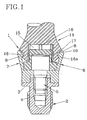
- Fig. 1 shows in cross section a coupling device 1 provided with a connecting device according to the invention.
- the connecting device is not limited to the embodiment of the coupling device 1 shown, but this does only form an example of a coupling device wherein the connecting device according to the invention can be included as an essential part.
- the coupling device 1 incorporates a flange fixture 2 formed as an implant, intended to be inserted by a surgical operation, preferably in the skull bone of the bearer of the hearing aid.
- the flange fixture or the implant 2 is made as a cylindric body preferably from titanium and near one of its ends it is provided with a radial flange 3, arranged in implanted position to engage the skull bone, such as shown in Fig. 2.
- a threaded blind hole 4 which receives a spacer screw 5 lockable thereto by thread engagement, and by means of which a first coupling part 6, in form of a substantially cup-shaped female part is anchored to the flange fixture 2, said first coupling part having a central through bore, through which extends the shaft of the spacer screw 5.
- the edge of the screw head retains the first coupling part 6 against the area about the bore in the flange fixture.
- the first coupling part 6 On its side turned away from the flange fixture 2, the first coupling part 6 is equipped with an axial outwardly tapering annular side wall 7, with annular outer end surface 8 and an inwardly projecting concentric annular bead 9 adjacent the external end surface 8.
- the head of the screw 5 thus protrudes upwards inside the space formed by the side wall 7 in the first coupling part, and the head of the screw is covered by a cap-formed covering washer 10, which at its upper portion leaves an annular slot, which extends from the outer end of the conically flaring side wall 7 and beyond its inwardly directed annular bead 9.
- the first coupling part 6 is designed as a rigid metal structure made from a high-quality material, it has substantially no resiliency whatsoever, not even at the outer end of its conically flaring side wall 7.
- the covering washer 10 is preferably manufactured from plastic material, and forms one of the vital members of the connecting device such as described in detail hereinafter.
- the coupling device 1 also incorporates a second coupling part 11, which, as can be seen from Fig. 2, in a proper, not further shown manner, with a shaft portion is connected to a hearing apparatus 12, of a type known per se, and in Fig. 2 is also shown how the implant 2 penetrates the skin 13 and is anchored in the skull bone 14.
- this second coupling part 11 is made as a male part with a recess 15 arranged in the forward portion thereof and concentric therewith, and being of a size, permitting that the recess is brought down over and encloses the upper portion of the covering washer 10 with clearance.
- the second coupling part or the male part 11 at its recess-provided end is equipped with an external, circumferential groove 16 with an engagement surface 16a formed at the free edge and adapted to form a seat for the annular bead 9 when the male part 11 is introduced into the annular slot in the first coupling part or the female part 6.
- the male part 11 is also provided with a radial, circumferential flange 17, which when the annular bead 9 is situated against the engagement surface 16a in the groove 16 in the male part engages the end surface 8 on the female part 6.
- the annular engagement surfaces between the end surface 8 and the flange 17 and also between the annular bead 9 and the engagement surface 16a form signal transferring surfaces between the first 6 and second 11 coupling parts of the coupling device.
- the portion of the second coupling part - the male part 11 - having the inner recess 15, is made resilient in order to permit simple snap-in introduction of the male part 11 into the annular slot in the female part 6.
- This resiliency can be obtained in different manners, e.g. in that the male part is provided with axial slots 18 in the material around the recess 15, and/or that the entire male part 11 is made in an elastic material, e.g. plastic.
- Fig. 3 shows in a view corresponding to Fig. 1, the coupling device in cross section, whereby the covering washer 10 is shown un-sectioned. From this view in combination with the sectioned illustration according to Fig. 1, it can be seen, that the covering washer 10 has a trough-shaped, substantially cylindrical portion 10a, which at its open end has a flanged portion 10b with bigger diameter than the through-formed portion 10a. On this flanged portion 10b there is provided on the upper side at least one, and preferably a number of bosses 19, which, when there are more than one boss, preferably are arranged to be symmetrically distributed along the flange portion 10b. These bosses 19 may arbitrarily be radially arranged ridges or point-shaped bosses, whereby however it is convenient that they are smoothly rounded or ramp-shaped in the circumferential direction of the flange portion 10b.
- Fig. 4 is shown how the second coupling part 11 has been turned, i.e. has been rotated in its seat formed by the annular wall 7 of the first coupling part, whereby mutually spaced apart, elongated wall portions 20 in the second coupling part 11 during the turning have been situated just in front of the bosses in the covering washer 10, whereby during the turning the boss or bosses 19, urge the second coupling part 11 outwards thus that its circumferential groove 16 is brought out off engagement with the annular bead 9 in the first coupling part 6.
- the implant is subjected to equally big forces in the connection direction by the wall portions 20, which press .
- the implant is not subjected to any forces, which might jeopardize or disturb its arresting in the inoperated position. Furthermore it is easy to rotate the second coupling part 11, which is anchored in the hearing apparatus (see Fig. 2).
- Fig. 5 to 7 is shown a somewhat modified embodiment of the second coupling part forming part of the coupling according to Fig.s and here provided with the reference numeral 11'.
- Fig. 5 thus is shown the second coupling part 11', from its coupling side, whereas Fig. 6 shows a cross section along line VI-VI and Fig. 7 a section along line VII-VII in Fig. 5.
- the second coupling part in this embodiment constitutes a substantially sleeve formed rotation body with a number of slots 18 and alternating wall portions 20, 21 of different lengths, which at turning of the coupling part 11' in its coupling position, will become situated alternatingly in front of the bosses 19 in the covering washer 10 belonging to the first coupling part 6.
- the shorter wall portions 21 are situated just in front of the bosses 19, the coupling parts are in engagement with each other, whereas they as described above are urged apart when the longer wall portions 20 have been turned to positions just in front of the bosses 19.
- the coupling part 11' shown in Fig.s 5-7 differ from the embodiment according to Fig.s 1-4 in that it is provided with a threaded coaxial bore 22, for a not shown attachment part of a hearing apparatus.
- both coupling parts are mutually rotatable and provided in their surfaces facing each other with portions, which in certain mutual rotational positions allow the parts to be interconnected, whereas they in other mutual rotational positions together have an overall linear length, which exceeds the depth to which the coupling parts can be in engagement with each other.
- the invention has been described in connection to a skull bone anchored hearing aid, but the connecting device according to the invention can of course also be used in other cases with devices or apparatuses of other kinds, which are connected to implants.
Landscapes
- Health & Medical Sciences (AREA)
- General Health & Medical Sciences (AREA)
- Otolaryngology (AREA)
- Neurosurgery (AREA)
- Physics & Mathematics (AREA)
- Engineering & Computer Science (AREA)
- Acoustics & Sound (AREA)
- Signal Processing (AREA)
- Prostheses (AREA)
- Dental Prosthetics (AREA)
- Auxiliary Devices For And Details Of Packaging Control (AREA)
- Details Of Connecting Devices For Male And Female Coupling (AREA)
Claims (7)
- Verbindungsvorrichtung zwischen einem Implantat (2) und einer damit verbundenen Vorrichtung (12), wobei die Verbindungsvorrichtung ein erstes und ein zweites Kupplungsteil (6 bzw. 11) enthält, wobei eines der Teile (11) in Kupplungsposition elastisch durch Einschnappwirkung in einer Vertiefung gehalten wird, die in dem anderen der Teile (6) vorhanden ist, wobei die Vertiefung eine Tiefe hat, die es dem zweiten Kupplungsteil ermöglicht, in Kupplungsposition in dieses hinein vorzustehen, und wobei die Kupplungsteile (6, 11) in Kupplungsposition mit gegenseitigem Stoßkontakt, der durch ringförmige Eingriffsflächen bewirkt wird, und im Wesentlichen in axialer Verlängerung zueinander angeordnet sind, so sie zueinander um eine im Wesentlichen gemeinsame Achse gedreht werden können, dadurch gekennzeichnet, dass:wenigstens eines der Kupplungsteile (6, 11) mit wenigstens einem Element (19) versehen ist, das zusammen mit dem anderen Kupplungsteil (11, 6) in wenigstens einer Drehposition der zwei Kupplungsteile zueinander eine gemeinsame Gesamt-Axial-Längsabmessung hat, durch die das in die Vertiefung eingeführte und durch Einschnappwirkung darin gehaltene Teil in miteinander verbundener Position einen Abstand zu dem anderen Kupplungsteil hat, und das zusammen mit dem anderen Kupplungsteil in wenigstens einer anderen Drehposition zueinander eine gemeinsame Gesamt-Axial-Längsabmessung hat, durch die ein Lösen der Einschnappwirkung der Kupplungsteile bewirkt wird, so dass die Kupplungsteile während der Drehung der Kupplungsteile zueinander in die wenigstens eine andere Drehposition zueinander ohne axialen Einfluss auf das Implantat auseinandergebracht werden.
- Vorrichtung nach Anspruch 1, dadurch gekennzeichnet, dass jedes des wenigstens einen Elements (19) durch einen Vorsprung in einem der Kupplungsteile (6) gebildet wird, während das andere Kupplungsteil (11) mit axialen Abschnitten (20, 21) unterschiedlicher Länge versehen ist, so dass der Vorsprung (19) und die axialen Abschnitte (21) in dem anderen Kupplungsteil (11), die kürzere Länge haben, zusammen axial kürzer sind als die axiale Tiefe der Vertiefung oder dieser entsprechen, während der Vorsprung (19) und die axialen Abschnitte (20) in dem anderen Kupplungsteil (11), die größere Länge haben, zusammen axial länger sind als die axiale Tiefe der Vertiefung.
- Vorrichtung nach Anspruch 2, dadurch gekennzeichnet, dass:die Vorsprünge (19) an einem separaten Teil (10) vorhanden sind, das nicht drehbar an einem der Kupplungsteile (6) angeordnet ist.
- Vorrichtung nach Anspruch 2 oder 3, dadurch gekennzeichnet, dass die Vorsprünge (19) als Stege ausgeführt sind, die sich radial zu der im Wesentlichen gemeinsamen Drehachse für die zwei Kupplungsteile erstrecken.
- Vorrichtung nach einem der Ansprüche 2 oder 3, dadurch gekennzeichnet, dass die Vorsprünge (19) als punktförmige erhabene Abschnitte ausgeführt sind, die an einem Umfang der im Wesentlichen gemeinsamen Drehachse für die zwei Kupplungsteile vorhanden sind.
- Vorrichtung nach einem der vorangehenden Ansprüche, dadurch gekennzeichnet, dass:die Vorsprünge (19) abgerundete Flächen in wenigstens einer Richtung der Drehung um die gemeinsame Drehachse haben.
- Vorrichtung nach einem der vorangehenden Ansprüche, dadurch gekennzeichnet, dass:die Vorrichtung (12), mit der das Implantat (2) über eine Lösevorrichtung nach einem der vorangehenden Ansprüche verbunden ist, durch eine schwingungserregende Hörhilfe gebildet wird.
Applications Claiming Priority (2)
| Application Number | Priority Date | Filing Date | Title |
|---|---|---|---|
| SE9404189A SE503790C2 (sv) | 1994-12-02 | 1994-12-02 | Urkopplingsanordning för implantatkoppling vid hörapparat |
| SE9404189 | 1994-12-02 |
Publications (3)
| Publication Number | Publication Date |
|---|---|
| EP0715839A2 EP0715839A2 (de) | 1996-06-12 |
| EP0715839A3 EP0715839A3 (de) | 1998-03-11 |
| EP0715839B1 true EP0715839B1 (de) | 2002-09-11 |
Family
ID=20396201
Family Applications (1)
| Application Number | Title | Priority Date | Filing Date |
|---|---|---|---|
| EP95850213A Expired - Lifetime EP0715839B1 (de) | 1994-12-02 | 1995-11-30 | Vorrichtung für implantierte Kupplung in Hörhilfen |
Country Status (7)
| Country | Link |
|---|---|
| US (1) | US5935170A (de) |
| EP (1) | EP0715839B1 (de) |
| AT (1) | ATE223683T1 (de) |
| DE (1) | DE69528138T2 (de) |
| DK (1) | DK0715839T3 (de) |
| ES (1) | ES2182881T3 (de) |
| SE (1) | SE503790C2 (de) |
Families Citing this family (47)
| Publication number | Priority date | Publication date | Assignee | Title |
|---|---|---|---|---|
| SE503790C2 (sv) * | 1994-12-02 | 1996-09-02 | P & B Res Ab | Urkopplingsanordning för implantatkoppling vid hörapparat |
| SE514631C2 (sv) * | 1997-06-06 | 2001-03-26 | P & B Res Ab | Anordning vid implantat för förankring och energiöverföring |
| SE513670C2 (sv) | 1997-12-18 | 2000-10-16 | Grogrunden Ab Nr 444 | Percutan benförankrad genomföringsanordning |
| DE19948375B4 (de) * | 1999-10-07 | 2004-04-01 | Phonak Ag | Anordnung zum mechanischen Ankoppeln eines Treibers an eine Ankoppelstelle der Ossikelkette |
| DE10047388C1 (de) * | 2000-09-25 | 2002-01-10 | Implex Hear Tech Ag | Mindestens teilweise implantierbares Hörsystem |
| US6705985B2 (en) | 2001-09-28 | 2004-03-16 | Otologics Llc | Apparatus and method for ossicular fixation of implantable hearing aid actuator |
| US20030229262A1 (en) * | 2001-11-20 | 2003-12-11 | Easter James Roy | Apparatus and method for ossicular fixation of implantable hearing aid actuator |
| NL1019891C2 (nl) * | 2002-02-01 | 2003-08-04 | Starquick Internat Ltd | Bevestiging van een voorwerp, zoals een pijpbeugel. |
| JP4262470B2 (ja) * | 2002-11-07 | 2009-05-13 | 株式会社ニフコ | 本留め用の雄パーツを有する連結具 |
| US7160244B2 (en) * | 2004-05-10 | 2007-01-09 | Patrik Westerkull | Arrangement for a hearing aid |
| US20070142697A1 (en) * | 2005-12-16 | 2007-06-21 | Robert Edwin Schneider | Apparatus for connection of implantable devices to the auditory system |
| US20080004486A1 (en) * | 2006-06-14 | 2008-01-03 | Otologics, Llc | Compressive coupling of an implantable hearing aid actuator to an auditory component |
| US7722525B2 (en) | 2007-05-24 | 2010-05-25 | Otologics, Llc | Lateral coupling of an implantable hearing aid actuator to an auditory component |
| WO2009049320A1 (en) | 2007-10-12 | 2009-04-16 | Earlens Corporation | Multifunction system and method for integrated hearing and communiction with noise cancellation and feedback management |
| US8401213B2 (en) * | 2008-03-31 | 2013-03-19 | Cochlear Limited | Snap-lock coupling system for a prosthetic device |
| US8542857B2 (en) * | 2008-03-31 | 2013-09-24 | Cochlear Limited | Bone conduction device with a movement sensor |
| US8737649B2 (en) * | 2008-03-31 | 2014-05-27 | Cochlear Limited | Bone conduction device with a user interface |
| WO2009155358A1 (en) | 2008-06-17 | 2009-12-23 | Earlens Corporation | Optical electro-mechanical hearing devices with separate power and signal components |
| DK3509324T3 (da) | 2008-09-22 | 2023-10-02 | Earlens Corp | Balancerede armaturindretninger og fremgangsmåder til at høre |
| SE0900372A1 (sv) * | 2009-03-24 | 2010-06-15 | Osseofon Ab | Benledningsvibratorkonstruktion med förbättrad högfrekvensrespons |
| EP2252079A1 (de) | 2009-05-14 | 2010-11-17 | Oticon A/S | Knochenverankerte knochenleitende Hörhilfe |
| US9544700B2 (en) | 2009-06-15 | 2017-01-10 | Earlens Corporation | Optically coupled active ossicular replacement prosthesis |
| CN102640435B (zh) | 2009-06-18 | 2016-11-16 | 伊尔莱茵斯公司 | 光学耦合的耳蜗植入系统及方法 |
| US8401214B2 (en) | 2009-06-18 | 2013-03-19 | Earlens Corporation | Eardrum implantable devices for hearing systems and methods |
| WO2011005479A2 (en) * | 2009-06-22 | 2011-01-13 | SoundBeam LLC | Optically coupled bone conduction systems and methods |
| CN102598714A (zh) | 2009-06-22 | 2012-07-18 | 音束有限责任公司 | 圆窗耦合的听力系统和方法 |
| US8594356B2 (en) * | 2010-04-29 | 2013-11-26 | Cochlear Limited | Bone conduction device having limited range of travel |
| WO2012088187A2 (en) | 2010-12-20 | 2012-06-28 | SoundBeam LLC | Anatomically customized ear canal hearing apparatus |
| US11843918B2 (en) | 2011-10-11 | 2023-12-12 | Cochlear Limited | Bone conduction implant |
| US20140179985A1 (en) * | 2012-12-21 | 2014-06-26 | Marcus ANDERSSON | Prosthesis adapter |
| US10757516B2 (en) * | 2013-10-29 | 2020-08-25 | Cochlear Limited | Electromagnetic transducer with specific interface geometries |
| EP3131312A1 (de) | 2013-11-25 | 2017-02-15 | Oticon Medical A/S | Hörgeräteverbindungssystem |
| US10034103B2 (en) | 2014-03-18 | 2018-07-24 | Earlens Corporation | High fidelity and reduced feedback contact hearing apparatus and methods |
| US9800982B2 (en) | 2014-06-18 | 2017-10-24 | Cochlear Limited | Electromagnetic transducer with expanded magnetic flux functionality |
| EP3169396B1 (de) | 2014-07-14 | 2021-04-21 | Earlens Corporation | Gleitende vorspannung und spitzenunterdrückung für optische hörgeräte |
| WO2016030853A2 (en) * | 2014-08-28 | 2016-03-03 | Cochlear Limited | Bone fixture for a medical prosthesis |
| US9924276B2 (en) | 2014-11-26 | 2018-03-20 | Earlens Corporation | Adjustable venting for hearing instruments |
| EP3355801B1 (de) | 2015-10-02 | 2021-05-19 | Earlens Corporation | Angepasste gehörgangvorrichtung zur arzneimittelabgabe |
| US10321247B2 (en) | 2015-11-27 | 2019-06-11 | Cochlear Limited | External component with inductance and mechanical vibratory functionality |
| US10306381B2 (en) | 2015-12-30 | 2019-05-28 | Earlens Corporation | Charging protocol for rechargable hearing systems |
| US10492010B2 (en) | 2015-12-30 | 2019-11-26 | Earlens Corporations | Damping in contact hearing systems |
| US11350226B2 (en) | 2015-12-30 | 2022-05-31 | Earlens Corporation | Charging protocol for rechargeable hearing systems |
| US20180077504A1 (en) | 2016-09-09 | 2018-03-15 | Earlens Corporation | Contact hearing systems, apparatus and methods |
| WO2018093733A1 (en) | 2016-11-15 | 2018-05-24 | Earlens Corporation | Improved impression procedure |
| US11078950B2 (en) * | 2018-02-26 | 2021-08-03 | Raytheon Company | Fastener biasing system |
| WO2019173470A1 (en) | 2018-03-07 | 2019-09-12 | Earlens Corporation | Contact hearing device and retention structure materials |
| WO2019199680A1 (en) | 2018-04-09 | 2019-10-17 | Earlens Corporation | Dynamic filter |
Family Cites Families (10)
| Publication number | Priority date | Publication date | Assignee | Title |
|---|---|---|---|---|
| US2367458A (en) * | 1943-07-10 | 1945-01-16 | Coplen George | Drill bit |
| US3034798A (en) * | 1960-03-22 | 1962-05-15 | True Temper Corp | Fishing rod handles |
| DE3030132A1 (de) * | 1980-08-08 | 1982-03-18 | Zuch, Erhard H., 4930 Detmold | Elektroakustisches geraet mit einem zahnhoerer |
| SE431705B (sv) * | 1981-12-01 | 1984-02-20 | Bo Hakansson | Koppling, foretredesvis avsedd for mekanisk overforing av ljudinformation till skallbenet pa en horselskadad person |
| FR2524794A1 (fr) * | 1982-04-08 | 1983-10-14 | Oreal | Appareil demontable comportant un accouplement a double baionnette |
| JPS5929409U (ja) * | 1982-08-20 | 1984-02-23 | 株式会社ニフコ | 部品取付け用クリツプ |
| US4486918A (en) * | 1983-04-29 | 1984-12-11 | Motorola, Inc. | Snap action removable knob |
| SE447947B (sv) * | 1985-05-10 | 1986-12-22 | Bo Hakansson | Anordning vid en horapparat |
| US5193961A (en) * | 1992-02-12 | 1993-03-16 | Illinois Tool Works Inc. | Pin and grommet |
| SE503790C2 (sv) * | 1994-12-02 | 1996-09-02 | P & B Res Ab | Urkopplingsanordning för implantatkoppling vid hörapparat |
-
1994
- 1994-12-02 SE SE9404189A patent/SE503790C2/sv not_active IP Right Cessation
-
1995
- 1995-11-30 AT AT95850213T patent/ATE223683T1/de not_active IP Right Cessation
- 1995-11-30 DK DK95850213T patent/DK0715839T3/da active
- 1995-11-30 EP EP95850213A patent/EP0715839B1/de not_active Expired - Lifetime
- 1995-11-30 DE DE69528138T patent/DE69528138T2/de not_active Expired - Lifetime
- 1995-11-30 ES ES95850213T patent/ES2182881T3/es not_active Expired - Lifetime
-
1997
- 1997-09-30 US US08/941,492 patent/US5935170A/en not_active Expired - Lifetime
Also Published As
| Publication number | Publication date |
|---|---|
| US5935170A (en) | 1999-08-10 |
| EP0715839A2 (de) | 1996-06-12 |
| EP0715839A3 (de) | 1998-03-11 |
| ES2182881T3 (es) | 2003-03-16 |
| SE9404189D0 (sv) | 1994-12-02 |
| DE69528138T2 (de) | 2003-04-24 |
| DK0715839T3 (da) | 2003-01-20 |
| DE69528138D1 (de) | 2002-10-17 |
| ATE223683T1 (de) | 2002-09-15 |
| SE503790C2 (sv) | 1996-09-02 |
| SE9404189L (sv) | 1996-06-03 |
Similar Documents
| Publication | Publication Date | Title |
|---|---|---|
| EP0715839B1 (de) | Vorrichtung für implantierte Kupplung in Hörhilfen | |
| EP0715838B1 (de) | Vorrichtung für Hörhilfe | |
| EP2252082B1 (de) | Knochenverankerte knochenleitende Hörhilfesystem | |
| ES2378588T3 (es) | Parte de recepción para recibir una varilla para acoplar la varilla en un elemento de anclaje óseo y dispositivo de anclaje óseo con tal parte de recepción | |
| US5378147A (en) | Ventral telescope | |
| US4792337A (en) | Acetabulum part for a total hip prosthesis | |
| US5417692A (en) | Bone fixation and fusion system | |
| CA2208832C (en) | Connector plug for multi-component orthopedic implant | |
| EP1633284B1 (de) | Implantatvorrichtung | |
| JPH11253472A (ja) | 股臼プロテ―ゼ | |
| WO2009015103A1 (en) | Coupling apparatus for a bone anchored hearing device | |
| JPH11510720A (ja) | スペース保持部材として脊柱の椎体間に挿入する生体埋め込み部材 | |
| EP2844194B1 (de) | Umgekehrte humerusschale mit verstellbarem winkel | |
| US20230097918A1 (en) | Annular resilient retention member | |
| US5658346A (en) | Inner shell for an artificial hip joint socket | |
| US20160175116A1 (en) | Medical force measuring system | |
| AU2005221377A1 (en) | Prosthetic limb attachment | |
| ES2908716T3 (es) | Sistema de anclaje para fijar una prótesis a un hueso largo del cuerpo humano | |
| KR20250048047A (ko) | 음경을 영구적으로 연장하기 위한 장치 | |
| CA2823557C (en) | A socket, in particular an acetabular socket for a hip endoprosthesis | |
| CN210521147U (zh) | 胸腰椎植入件以及胸腰椎人工椎体 | |
| KR101860636B1 (ko) | 임플란트용 드릴장치 | |
| EP3866727B1 (de) | Werkzeug zum einschrauben eines zahnärztlichen implantats und dessen halteelement für den schraubendreher | |
| HU220951B1 (en) | Joint-prosthesis for small joints |
Legal Events
| Date | Code | Title | Description |
|---|---|---|---|
| PUAI | Public reference made under article 153(3) epc to a published international application that has entered the european phase |
Free format text: ORIGINAL CODE: 0009012 |
|
| AK | Designated contracting states |
Kind code of ref document: A2 Designated state(s): AT BE CH DE DK ES FR GB IE IT LI NL SE |
|
| PUAL | Search report despatched |
Free format text: ORIGINAL CODE: 0009013 |
|
| AK | Designated contracting states |
Kind code of ref document: A3 Designated state(s): AT BE CH DE DK ES FR GB IE IT LI NL SE |
|
| 17P | Request for examination filed |
Effective date: 19980504 |
|
| 17Q | First examination report despatched |
Effective date: 20001114 |
|
| RTI1 | Title (correction) |
Free format text: A CONNECTING DEVICE FOR IMPLANT COUPLING AT HEARING AIDS |
|
| GRAG | Despatch of communication of intention to grant |
Free format text: ORIGINAL CODE: EPIDOS AGRA |
|
| GRAG | Despatch of communication of intention to grant |
Free format text: ORIGINAL CODE: EPIDOS AGRA |
|
| GRAH | Despatch of communication of intention to grant a patent |
Free format text: ORIGINAL CODE: EPIDOS IGRA |
|
| RTI1 | Title (correction) |
Free format text: A CONNECTING DEVICE FOR IMPLANT COUPLING AT HEARING AIDS |
|
| GRAH | Despatch of communication of intention to grant a patent |
Free format text: ORIGINAL CODE: EPIDOS IGRA |
|
| GRAA | (expected) grant |
Free format text: ORIGINAL CODE: 0009210 |
|
| AK | Designated contracting states |
Kind code of ref document: B1 Designated state(s): AT BE CH DE DK ES FR GB IE IT LI NL SE |
|
| REF | Corresponds to: |
Ref document number: 223683 Country of ref document: AT Date of ref document: 20020915 Kind code of ref document: T |
|
| REG | Reference to a national code |
Ref country code: GB Ref legal event code: FG4D |
|
| REG | Reference to a national code |
Ref country code: CH Ref legal event code: EP |
|
| REG | Reference to a national code |
Ref country code: IE Ref legal event code: FG4D |
|
| REF | Corresponds to: |
Ref document number: 69528138 Country of ref document: DE Date of ref document: 20021017 |
|
| PG25 | Lapsed in a contracting state [announced via postgrant information from national office to epo] |
Ref country code: IE Free format text: LAPSE BECAUSE OF NON-PAYMENT OF DUE FEES Effective date: 20021202 |
|
| PG25 | Lapsed in a contracting state [announced via postgrant information from national office to epo] |
Ref country code: SE Free format text: LAPSE BECAUSE OF FAILURE TO SUBMIT A TRANSLATION OF THE DESCRIPTION OR TO PAY THE FEE WITHIN THE PRESCRIBED TIME-LIMIT Effective date: 20021211 |
|
| REG | Reference to a national code |
Ref country code: DK Ref legal event code: T3 |
|
| REG | Reference to a national code |
Ref country code: CH Ref legal event code: AEN Free format text: DAS PATENT IST AUFGRUND DES WEITERBEHANDLUNGSANTRAGS VOM 14.01.2003 REAKTIVIERT WORDEN. |
|
| ET | Fr: translation filed | ||
| REG | Reference to a national code |
Ref country code: CH Ref legal event code: NV Representative=s name: KATZAROV S.A. |
|
| REG | Reference to a national code |
Ref country code: ES Ref legal event code: FG2A Ref document number: 2182881 Country of ref document: ES Kind code of ref document: T3 |
|
| PLBE | No opposition filed within time limit |
Free format text: ORIGINAL CODE: 0009261 |
|
| STAA | Information on the status of an ep patent application or granted ep patent |
Free format text: STATUS: NO OPPOSITION FILED WITHIN TIME LIMIT |
|
| 26N | No opposition filed |
Effective date: 20030612 |
|
| REG | Reference to a national code |
Ref country code: IE Ref legal event code: MM4A |
|
| REG | Reference to a national code |
Ref country code: CH Ref legal event code: PUE Owner name: PERCUTIS AB Free format text: P & B RESEARCH AB#SPLINTVEDSGATAN 7#416 80 GOETEBORG (SE) -TRANSFER TO- PERCUTIS AB#SPLINTVEDSGATAN 7#41680 GOETEBORG (SE) |
|
| REG | Reference to a national code |
Ref country code: FR Ref legal event code: TP |
|
| REG | Reference to a national code |
Ref country code: GB Ref legal event code: 732E Free format text: REGISTERED BETWEEN 20090716 AND 20090722 |
|
| NLS | Nl: assignments of ep-patents |
Owner name: PERCUTIS AB Effective date: 20090617 |
|
| PGFP | Annual fee paid to national office [announced via postgrant information from national office to epo] |
Ref country code: GB Payment date: 20091125 Year of fee payment: 15 Ref country code: FR Payment date: 20091217 Year of fee payment: 15 Ref country code: CH Payment date: 20100226 Year of fee payment: 15 |
|
| PGFP | Annual fee paid to national office [announced via postgrant information from national office to epo] |
Ref country code: ES Payment date: 20100514 Year of fee payment: 15 |
|
| PGFP | Annual fee paid to national office [announced via postgrant information from national office to epo] |
Ref country code: AT Payment date: 20100506 Year of fee payment: 15 |
|
| PGFP | Annual fee paid to national office [announced via postgrant information from national office to epo] |
Ref country code: BE Payment date: 20100505 Year of fee payment: 15 |
|
| PGFP | Annual fee paid to national office [announced via postgrant information from national office to epo] |
Ref country code: NL Payment date: 20101110 Year of fee payment: 16 Ref country code: DK Payment date: 20101230 Year of fee payment: 16 |
|
| PGFP | Annual fee paid to national office [announced via postgrant information from national office to epo] |
Ref country code: DE Payment date: 20101124 Year of fee payment: 16 |
|
| PG25 | Lapsed in a contracting state [announced via postgrant information from national office to epo] |
Ref country code: IT Free format text: LAPSE BECAUSE OF NON-PAYMENT OF DUE FEES Effective date: 20091130 |
|
| BERE | Be: lapsed |
Owner name: PERCUTIS A.B. Effective date: 20101130 |
|
| REG | Reference to a national code |
Ref country code: CH Ref legal event code: PL |
|
| GBPC | Gb: european patent ceased through non-payment of renewal fee |
Effective date: 20101130 |
|
| PG25 | Lapsed in a contracting state [announced via postgrant information from national office to epo] |
Ref country code: CH Free format text: LAPSE BECAUSE OF NON-PAYMENT OF DUE FEES Effective date: 20101130 Ref country code: LI Free format text: LAPSE BECAUSE OF NON-PAYMENT OF DUE FEES Effective date: 20101130 |
|
| PGFP | Annual fee paid to national office [announced via postgrant information from national office to epo] |
Ref country code: IT Payment date: 20100510 Year of fee payment: 15 |
|
| PGRI | Patent reinstated in contracting state [announced from national office to epo] |
Ref country code: IT Effective date: 20110616 |
|
| REG | Reference to a national code |
Ref country code: FR Ref legal event code: ST Effective date: 20110801 |
|
| PG25 | Lapsed in a contracting state [announced via postgrant information from national office to epo] |
Ref country code: BE Free format text: LAPSE BECAUSE OF NON-PAYMENT OF DUE FEES Effective date: 20101130 Ref country code: AT Free format text: LAPSE BECAUSE OF NON-PAYMENT OF DUE FEES Effective date: 20101130 |
|
| PG25 | Lapsed in a contracting state [announced via postgrant information from national office to epo] |
Ref country code: FR Free format text: LAPSE BECAUSE OF NON-PAYMENT OF DUE FEES Effective date: 20101130 |
|
| PG25 | Lapsed in a contracting state [announced via postgrant information from national office to epo] |
Ref country code: GB Free format text: LAPSE BECAUSE OF NON-PAYMENT OF DUE FEES Effective date: 20101130 |
|
| PGRI | Patent reinstated in contracting state [announced from national office to epo] |
Ref country code: IT Effective date: 20110616 |
|
| REG | Reference to a national code |
Ref country code: ES Ref legal event code: FD2A Effective date: 20120110 |
|
| PG25 | Lapsed in a contracting state [announced via postgrant information from national office to epo] |
Ref country code: ES Free format text: LAPSE BECAUSE OF NON-PAYMENT OF DUE FEES Effective date: 20101201 |
|
| REG | Reference to a national code |
Ref country code: NL Ref legal event code: V1 Effective date: 20120601 |
|
| REG | Reference to a national code |
Ref country code: DK Ref legal event code: EBP |
|
| PG25 | Lapsed in a contracting state [announced via postgrant information from national office to epo] |
Ref country code: NL Free format text: LAPSE BECAUSE OF NON-PAYMENT OF DUE FEES Effective date: 20120601 |
|
| REG | Reference to a national code |
Ref country code: DE Ref legal event code: R119 Ref document number: 69528138 Country of ref document: DE Effective date: 20120601 |
|
| PG25 | Lapsed in a contracting state [announced via postgrant information from national office to epo] |
Ref country code: DK Free format text: LAPSE BECAUSE OF NON-PAYMENT OF DUE FEES Effective date: 20111130 |
|
| PG25 | Lapsed in a contracting state [announced via postgrant information from national office to epo] |
Ref country code: DE Free format text: LAPSE BECAUSE OF NON-PAYMENT OF DUE FEES Effective date: 20120601 |