EP0715863B1 - Katheter - Google Patents
Katheter Download PDFInfo
- Publication number
- EP0715863B1 EP0715863B1 EP95308049A EP95308049A EP0715863B1 EP 0715863 B1 EP0715863 B1 EP 0715863B1 EP 95308049 A EP95308049 A EP 95308049A EP 95308049 A EP95308049 A EP 95308049A EP 0715863 B1 EP0715863 B1 EP 0715863B1
- Authority
- EP
- European Patent Office
- Prior art keywords
- catheter
- section
- ribbon
- stiffener
- tubing member
- Prior art date
- Legal status (The legal status is an assumption and is not a legal conclusion. Google has not performed a legal analysis and makes no representation as to the accuracy of the status listed.)
- Expired - Lifetime
Links
- 239000003351 stiffener Substances 0.000 claims abstract description 48
- 239000000463 material Substances 0.000 claims description 50
- 230000001070 adhesive effect Effects 0.000 claims description 24
- 239000000853 adhesive Substances 0.000 claims description 23
- 229920000642 polymer Polymers 0.000 claims description 21
- 239000000203 mixture Substances 0.000 claims description 14
- -1 polyethylene Polymers 0.000 claims description 13
- 229910001220 stainless steel Inorganic materials 0.000 claims description 13
- 229910045601 alloy Inorganic materials 0.000 claims description 12
- 239000000956 alloy Substances 0.000 claims description 12
- 239000010935 stainless steel Substances 0.000 claims description 9
- BFMKFCLXZSUVPI-UHFFFAOYSA-N ethyl but-3-enoate Chemical compound CCOC(=O)CC=C BFMKFCLXZSUVPI-UHFFFAOYSA-N 0.000 claims description 8
- 239000004642 Polyimide Substances 0.000 claims description 6
- 229920001721 polyimide Polymers 0.000 claims description 6
- 239000004698 Polyethylene Substances 0.000 claims description 5
- 229920001577 copolymer Polymers 0.000 claims description 5
- 229920000573 polyethylene Polymers 0.000 claims description 5
- 239000004800 polyvinyl chloride Substances 0.000 claims description 5
- 239000004952 Polyamide Substances 0.000 claims description 4
- 239000004743 Polypropylene Substances 0.000 claims description 4
- 230000001464 adherent effect Effects 0.000 claims description 4
- 229920009441 perflouroethylene propylene Polymers 0.000 claims description 4
- 229920002647 polyamide Polymers 0.000 claims description 4
- 229920000728 polyester Polymers 0.000 claims description 4
- 229920001155 polypropylene Polymers 0.000 claims description 4
- 229920002635 polyurethane Polymers 0.000 claims description 4
- 239000004814 polyurethane Substances 0.000 claims description 4
- 229920000915 polyvinyl chloride Polymers 0.000 claims description 4
- 229910001080 W alloy Inorganic materials 0.000 claims description 3
- 229920001400 block copolymer Polymers 0.000 claims description 3
- HLXZNVUGXRDIFK-UHFFFAOYSA-N nickel titanium Chemical compound [Ti].[Ti].[Ti].[Ti].[Ti].[Ti].[Ti].[Ti].[Ti].[Ti].[Ti].[Ni].[Ni].[Ni].[Ni].[Ni].[Ni].[Ni].[Ni].[Ni].[Ni].[Ni].[Ni].[Ni].[Ni] HLXZNVUGXRDIFK-UHFFFAOYSA-N 0.000 claims description 3
- 229910001000 nickel titanium Inorganic materials 0.000 claims description 3
- 229920001343 polytetrafluoroethylene Polymers 0.000 claims description 3
- 239000004810 polytetrafluoroethylene Substances 0.000 claims description 3
- BQCIDUSAKPWEOX-UHFFFAOYSA-N 1,1-Difluoroethene Chemical compound FC(F)=C BQCIDUSAKPWEOX-UHFFFAOYSA-N 0.000 claims description 2
- 229920002313 fluoropolymer Polymers 0.000 claims description 2
- 239000004811 fluoropolymer Substances 0.000 claims description 2
- 238000011065 in-situ storage Methods 0.000 claims description 2
- 238000002844 melting Methods 0.000 claims description 2
- 230000008018 melting Effects 0.000 claims description 2
- ZONODCCBXBRQEZ-UHFFFAOYSA-N platinum tungsten Chemical compound [W].[Pt] ZONODCCBXBRQEZ-UHFFFAOYSA-N 0.000 claims description 2
- 229920002492 poly(sulfone) Polymers 0.000 claims description 2
- 230000015556 catabolic process Effects 0.000 claims 1
- 238000006731 degradation reaction Methods 0.000 claims 1
- 229920000139 polyethylene terephthalate Polymers 0.000 claims 1
- 239000005020 polyethylene terephthalate Substances 0.000 claims 1
- 230000005855 radiation Effects 0.000 claims 1
- 230000002792 vascular Effects 0.000 abstract description 9
- 208000027418 Wounds and injury Diseases 0.000 description 39
- 239000010410 layer Substances 0.000 description 23
- 238000000034 method Methods 0.000 description 15
- 238000004519 manufacturing process Methods 0.000 description 6
- 239000000758 substrate Substances 0.000 description 6
- 239000004809 Teflon Substances 0.000 description 5
- 229920006362 Teflon® Polymers 0.000 description 5
- 238000010276 construction Methods 0.000 description 5
- 229920003023 plastic Polymers 0.000 description 5
- 239000004033 plastic Substances 0.000 description 5
- 230000008901 benefit Effects 0.000 description 4
- 239000011248 coating agent Substances 0.000 description 4
- 238000000576 coating method Methods 0.000 description 4
- 239000002131 composite material Substances 0.000 description 4
- PCHJSUWPFVWCPO-UHFFFAOYSA-N gold Chemical compound [Au] PCHJSUWPFVWCPO-UHFFFAOYSA-N 0.000 description 4
- 229910052737 gold Inorganic materials 0.000 description 4
- 239000010931 gold Substances 0.000 description 4
- 229910052751 metal Inorganic materials 0.000 description 4
- 239000002184 metal Substances 0.000 description 4
- 239000002356 single layer Substances 0.000 description 4
- 210000005166 vasculature Anatomy 0.000 description 4
- 238000004804 winding Methods 0.000 description 4
- 239000004812 Fluorinated ethylene propylene Substances 0.000 description 3
- 229920001971 elastomer Polymers 0.000 description 3
- 208000014674 injury Diseases 0.000 description 3
- 229920001684 low density polyethylene Polymers 0.000 description 3
- 239000004702 low-density polyethylene Substances 0.000 description 3
- 230000002093 peripheral effect Effects 0.000 description 3
- 230000003014 reinforcing effect Effects 0.000 description 3
- 239000012779 reinforcing material Substances 0.000 description 3
- 230000008733 trauma Effects 0.000 description 3
- FDSYTWVNUJTPMA-UHFFFAOYSA-N 2-[3,9-bis(carboxymethyl)-3,6,9,15-tetrazabicyclo[9.3.1]pentadeca-1(15),11,13-trien-6-yl]acetic acid Chemical compound C1N(CC(O)=O)CCN(CC(=O)O)CCN(CC(O)=O)CC2=CC=CC1=N2 FDSYTWVNUJTPMA-UHFFFAOYSA-N 0.000 description 2
- RYGMFSIKBFXOCR-UHFFFAOYSA-N Copper Chemical compound [Cu] RYGMFSIKBFXOCR-UHFFFAOYSA-N 0.000 description 2
- PXHVJJICTQNCMI-UHFFFAOYSA-N Nickel Chemical compound [Ni] PXHVJJICTQNCMI-UHFFFAOYSA-N 0.000 description 2
- KDLHZDBZIXYQEI-UHFFFAOYSA-N Palladium Chemical compound [Pd] KDLHZDBZIXYQEI-UHFFFAOYSA-N 0.000 description 2
- 229920003235 aromatic polyamide Polymers 0.000 description 2
- TZCXTZWJZNENPQ-UHFFFAOYSA-L barium sulfate Chemical compound [Ba+2].[O-]S([O-])(=O)=O TZCXTZWJZNENPQ-UHFFFAOYSA-L 0.000 description 2
- 230000015572 biosynthetic process Effects 0.000 description 2
- 210000004204 blood vessel Anatomy 0.000 description 2
- 239000003814 drug Substances 0.000 description 2
- 239000000806 elastomer Substances 0.000 description 2
- 239000000835 fiber Substances 0.000 description 2
- 239000011152 fibreglass Substances 0.000 description 2
- 239000000945 filler Substances 0.000 description 2
- 229920001903 high density polyethylene Polymers 0.000 description 2
- 239000004700 high-density polyethylene Substances 0.000 description 2
- 230000000926 neurological effect Effects 0.000 description 2
- 229920001778 nylon Polymers 0.000 description 2
- 230000037361 pathway Effects 0.000 description 2
- BASFCYQUMIYNBI-UHFFFAOYSA-N platinum Chemical compound [Pt] BASFCYQUMIYNBI-UHFFFAOYSA-N 0.000 description 2
- 229920001296 polysiloxane Polymers 0.000 description 2
- 229920005989 resin Polymers 0.000 description 2
- 239000011347 resin Substances 0.000 description 2
- 210000004872 soft tissue Anatomy 0.000 description 2
- BFKJFAAPBSQJPD-UHFFFAOYSA-N tetrafluoroethene Chemical compound FC(F)=C(F)F BFKJFAAPBSQJPD-UHFFFAOYSA-N 0.000 description 2
- 230000001225 therapeutic effect Effects 0.000 description 2
- 229920001169 thermoplastic Polymers 0.000 description 2
- 229920005992 thermoplastic resin Polymers 0.000 description 2
- 239000004416 thermosoftening plastic Substances 0.000 description 2
- 210000001519 tissue Anatomy 0.000 description 2
- WFKWXMTUELFFGS-UHFFFAOYSA-N tungsten Chemical compound [W] WFKWXMTUELFFGS-UHFFFAOYSA-N 0.000 description 2
- 229910052721 tungsten Inorganic materials 0.000 description 2
- 239000010937 tungsten Substances 0.000 description 2
- KXGFMDJXCMQABM-UHFFFAOYSA-N 2-methoxy-6-methylphenol Chemical compound [CH]OC1=CC=CC([CH])=C1O KXGFMDJXCMQABM-UHFFFAOYSA-N 0.000 description 1
- 229920000049 Carbon (fiber) Polymers 0.000 description 1
- 241000321369 Cephalopholis fulva Species 0.000 description 1
- 229920000742 Cotton Polymers 0.000 description 1
- 229920000271 Kevlar® Polymers 0.000 description 1
- 229920003369 Kevlar® 49 Polymers 0.000 description 1
- 229920000106 Liquid crystal polymer Polymers 0.000 description 1
- 239000004977 Liquid-crystal polymers (LCPs) Substances 0.000 description 1
- 239000004677 Nylon Substances 0.000 description 1
- 229910001260 Pt alloy Inorganic materials 0.000 description 1
- ATJFFYVFTNAWJD-UHFFFAOYSA-N Tin Chemical compound [Sn] ATJFFYVFTNAWJD-UHFFFAOYSA-N 0.000 description 1
- 238000002399 angioplasty Methods 0.000 description 1
- 238000000137 annealing Methods 0.000 description 1
- 239000004760 aramid Substances 0.000 description 1
- 210000001367 artery Anatomy 0.000 description 1
- 230000000712 assembly Effects 0.000 description 1
- 238000000429 assembly Methods 0.000 description 1
- 230000005540 biological transmission Effects 0.000 description 1
- 229940036348 bismuth carbonate Drugs 0.000 description 1
- WMWLMWRWZQELOS-UHFFFAOYSA-N bismuth(III) oxide Inorganic materials O=[Bi]O[Bi]=O WMWLMWRWZQELOS-UHFFFAOYSA-N 0.000 description 1
- 238000009954 braiding Methods 0.000 description 1
- 210000004556 brain Anatomy 0.000 description 1
- 239000004917 carbon fiber Substances 0.000 description 1
- 239000003795 chemical substances by application Substances 0.000 description 1
- 230000006835 compression Effects 0.000 description 1
- 238000007906 compression Methods 0.000 description 1
- 210000004351 coronary vessel Anatomy 0.000 description 1
- 238000004132 cross linking Methods 0.000 description 1
- 230000032798 delamination Effects 0.000 description 1
- 230000001419 dependent effect Effects 0.000 description 1
- 239000000032 diagnostic agent Substances 0.000 description 1
- 229940039227 diagnostic agent Drugs 0.000 description 1
- GMZOPRQQINFLPQ-UHFFFAOYSA-H dibismuth;tricarbonate Chemical compound [Bi+3].[Bi+3].[O-]C([O-])=O.[O-]C([O-])=O.[O-]C([O-])=O GMZOPRQQINFLPQ-UHFFFAOYSA-H 0.000 description 1
- 201000010099 disease Diseases 0.000 description 1
- 208000037265 diseases, disorders, signs and symptoms Diseases 0.000 description 1
- 230000009977 dual effect Effects 0.000 description 1
- 230000002526 effect on cardiovascular system Effects 0.000 description 1
- 230000000694 effects Effects 0.000 description 1
- 239000013013 elastic material Substances 0.000 description 1
- 239000013536 elastomeric material Substances 0.000 description 1
- 229920006333 epoxy cement Polymers 0.000 description 1
- 239000004744 fabric Substances 0.000 description 1
- 230000004720 fertilization Effects 0.000 description 1
- 239000003527 fibrinolytic agent Substances 0.000 description 1
- 239000002657 fibrous material Substances 0.000 description 1
- 239000012530 fluid Substances 0.000 description 1
- 238000002594 fluoroscopy Methods 0.000 description 1
- 239000011521 glass Substances 0.000 description 1
- 210000004013 groin Anatomy 0.000 description 1
- 235000019589 hardness Nutrition 0.000 description 1
- 239000012761 high-performance material Substances 0.000 description 1
- 238000002513 implantation Methods 0.000 description 1
- 230000006872 improvement Effects 0.000 description 1
- 238000001802 infusion Methods 0.000 description 1
- 230000001678 irradiating effect Effects 0.000 description 1
- 239000004761 kevlar Substances 0.000 description 1
- 238000009940 knitting Methods 0.000 description 1
- 239000002648 laminated material Substances 0.000 description 1
- 239000004973 liquid crystal related substance Substances 0.000 description 1
- 210000004185 liver Anatomy 0.000 description 1
- 239000000155 melt Substances 0.000 description 1
- 150000002739 metals Chemical class 0.000 description 1
- 229910052759 nickel Inorganic materials 0.000 description 1
- RVTZCBVAJQQJTK-UHFFFAOYSA-N oxygen(2-);zirconium(4+) Chemical compound [O-2].[O-2].[Zr+4] RVTZCBVAJQQJTK-UHFFFAOYSA-N 0.000 description 1
- 229910052763 palladium Inorganic materials 0.000 description 1
- 230000035515 penetration Effects 0.000 description 1
- 229920001568 phenolic resin Polymers 0.000 description 1
- 239000005011 phenolic resin Substances 0.000 description 1
- 230000035479 physiological effects, processes and functions Effects 0.000 description 1
- 239000004014 plasticizer Substances 0.000 description 1
- 229910052697 platinum Inorganic materials 0.000 description 1
- 229920003055 poly(ester-imide) Polymers 0.000 description 1
- 229920006254 polymer film Polymers 0.000 description 1
- 229920000036 polyvinylpyrrolidone Polymers 0.000 description 1
- 235000013855 polyvinylpyrrolidone Nutrition 0.000 description 1
- 239000001267 polyvinylpyrrolidone Substances 0.000 description 1
- 230000008569 process Effects 0.000 description 1
- 230000002285 radioactive effect Effects 0.000 description 1
- 230000002787 reinforcement Effects 0.000 description 1
- 229910052703 rhodium Inorganic materials 0.000 description 1
- 239000010948 rhodium Substances 0.000 description 1
- MHOVAHRLVXNVSD-UHFFFAOYSA-N rhodium atom Chemical compound [Rh] MHOVAHRLVXNVSD-UHFFFAOYSA-N 0.000 description 1
- 102200163539 rs121912965 Human genes 0.000 description 1
- 239000005060 rubber Substances 0.000 description 1
- 239000000523 sample Substances 0.000 description 1
- 239000004447 silicone coating Substances 0.000 description 1
- 238000005476 soldering Methods 0.000 description 1
- 238000012414 sterilization procedure Methods 0.000 description 1
- 229920002994 synthetic fiber Polymers 0.000 description 1
- 239000012209 synthetic fiber Substances 0.000 description 1
- 229910052715 tantalum Inorganic materials 0.000 description 1
- GUVRBAGPIYLISA-UHFFFAOYSA-N tantalum atom Chemical compound [Ta] GUVRBAGPIYLISA-UHFFFAOYSA-N 0.000 description 1
- 229940124597 therapeutic agent Drugs 0.000 description 1
- 229920002725 thermoplastic elastomer Polymers 0.000 description 1
- 229960000103 thrombolytic agent Drugs 0.000 description 1
- 150000003608 titanium Chemical class 0.000 description 1
- 230000007704 transition Effects 0.000 description 1
- 239000002383 tung oil Substances 0.000 description 1
Images

Classifications
-
- A—HUMAN NECESSITIES
- A61—MEDICAL OR VETERINARY SCIENCE; HYGIENE
- A61M—DEVICES FOR INTRODUCING MEDIA INTO, OR ONTO, THE BODY; DEVICES FOR TRANSDUCING BODY MEDIA OR FOR TAKING MEDIA FROM THE BODY; DEVICES FOR PRODUCING OR ENDING SLEEP OR STUPOR
- A61M25/00—Catheters; Hollow probes
- A61M25/0043—Catheters; Hollow probes characterised by structural features
- A61M25/005—Catheters; Hollow probes characterised by structural features with embedded materials for reinforcement, e.g. wires, coils, braids
- A61M25/0053—Catheters; Hollow probes characterised by structural features with embedded materials for reinforcement, e.g. wires, coils, braids having a variable stiffness along the longitudinal axis, e.g. by varying the pitch of the coil or braid
-
- A—HUMAN NECESSITIES
- A61—MEDICAL OR VETERINARY SCIENCE; HYGIENE
- A61M—DEVICES FOR INTRODUCING MEDIA INTO, OR ONTO, THE BODY; DEVICES FOR TRANSDUCING BODY MEDIA OR FOR TAKING MEDIA FROM THE BODY; DEVICES FOR PRODUCING OR ENDING SLEEP OR STUPOR
- A61M25/00—Catheters; Hollow probes
- A61M25/0043—Catheters; Hollow probes characterised by structural features
- A61M25/005—Catheters; Hollow probes characterised by structural features with embedded materials for reinforcement, e.g. wires, coils, braids
Definitions
- This invention is a surgical device.
- it is a catheter suitable for accessing a tissue target within the body, typically a target which is accessible through the vascular system.
- a stiffener ribbon typically metallic, wound within the catheter body in such a way to create a catheter having an exceptionally thin wall and controlled stiffness.
- the stiffener ribbon is adhesively bonded to a flexible outer tubing member so to produce a catheter section which is very flexible but highly kink resistant.
- catheter sections made according to this invention may be used in conjunction with other catheter sections either using the concepts shown herein or made in other ways. Because of the effective strength and ability to retain a generally kink-free form, these catheters may be effectively used in sizes which are quite fine, e.g. 0.38 to 0.5 mm (0.015" to 0.020") in diameter, and usable within typical vascular catheters.
- Catheters are increasingly used to access remote regions of the human body and, in doing so, delivering diagnostic or therapeutic agents to those sites.
- catheters which use the circulatory system as the pathway to these treatment sites are especially practical.
- Catheters are also used to access other regions of the body, e.g., genito-urinary regions, for a variety of therapeutic and diagnostic reasons.
- One such treatment of diseases of the circulatory system is via angioplasty (PCTA).
- PCTA angioplasty
- Such a procedure uses catheters having balloons on their distal tips. It is similarly common that those catheters are used to deliver a radiopaque agent to the site in question prior to the PCTA procedure to view the problem prior to treatment.
- the target which one desires to access by catheter is within a soft tissue such as the liver or the brain. These are difficult sites to reach.
- the catheter must be introduced through a large artery such as those found in the groin or in the neck and then be passed through ever-narrower regions of the arterial system until the catheter reaches the selected site. Often such pathways will wind back upon themselves in a multi-looped path.
- These catheters are difficult to design and to utilize in that they must be fairly stiff at their proximal end so to allow the pushing and manipulation of the catheter as it progresses through the body, and yet must be sufficiently flexible at the distal end to allow passage of the catheter tip through the loops and increasingly smaller blood vessels mentioned above and yet at the same time not cause significant trauma to the blood vessel or to the surrounding tissue.
- a guidewire-aided catheter is considered to be both quite quick and somewhat more accurate than the other procedures.
- One such alternative procedure is the use of a flow-directed catheter. These devices often have a small balloon situated on the distal end of the catheter which may be alternately deflated and inflated as the need to select a route for the catheter is encountered.
- This invention is an adaptable one and may be used in a variety of catheter formats.
- the invention utilizes the concept of adhesively combining one or more polymeric tubes with one or more spirally wound ribbons (each wound in the same direction) to control the stiffness of the resultant catheter section or body.
- the construction technique allows the production of catheter sections having very small diameters -- diameters so small that the secondary catheters may be used interior to other vascular catheters, with or without guidewires.
- This catheter may be used in conjunction with a guidewire, but the catheter body may also be used as a flow-directed catheter with the attachment of a balloon or in combination with a specifically flexible tip, as is seen, for instance, in U.S. Patent No. 5,336,205 to Zenzen et al.
- catheters there are a number of catheters discussed in the literature which utilize catheter bodies having multiply wrapped reinforcing material. These catheters include structures having braided bands or ones in which the spirally.wound material is simply wound in one direction and the following layer or layers are wound in the other.
- Crippendorf, U.S. Patent 2,437,542 describes a "catheter-type instrument" which is typically used as a ureteral or urethral catheter.
- the physical design is said to be one having a distal section of greater flexibility and a proximal section of lesser flexibility.
- the device is made of intertwined threads of silk, cotton, or some synthetic fiber. It is made by impregnating a fabric-based tube with a stiffening medium which renders the tube stiff yet flexible. The thus-plasticized tubing is then dipped in some other medium to allow the formation of a flexible varnish-like layer.
- This latter material may be a tung oil base or a phenolic resin and a suitable plasticizer.
- this device is of the flexibility described herein. Additionally, it appears to be the type which is used in some region other than in the body's periphery or in its soft tissues.
- U.S. Patent No. 3,416,531 shows a catheter having braiding-edge walls.
- the device further has additional layers of other polymers such as TEFLON and the like.
- the strands found in the braiding in the walls appear to be threads having circular cross-sections.
- ribbon materials There is no suggestion of constructing a device using ribbon materials.
- the device is shown to be fairly stiff in that it is designed so that it may be bent using a fairly large handle at its proximal end.
- U.S. Patent No. 4,425,919, to Alston, Jr. et al. shows a multilayered catheter assembly using multi-stranded flat wire braid.
- the braid 14 in Figure 3 further covers an interior tubing or substrate 12.
- U.S. Patent No. 4,484,586 shows a method for the production of a hollow, conductive medical tubing.
- the conductive wires are placed in the walls of hollow tubing specifically for implantation in the human body, particularly for pacemaker leads.
- the tubing is preferably made of an annealed copper wire which has been coated with a body-compatible polymer such as a polyurethane or a silicone. After coating, the copper wire is wound into a tube. The wound substrate is then coated with still another polymer to produce a tubing having spiral conducting wires in its wall.
- U.S. Patent No. 4,832,681 to Lenck shows a method and apparatus useful for artificial fertilization.
- the device itself is a long portion of tubing which, depending upon its specific materials of construction, may be made somewhat stiffer by the addition of a spiral reinforcement comprising stainless steel wire.
- U.S. Patent No. 4,981,478, to Evard et al. discloses a multi-sectioned or composite vascular catheter.
- the interior section of the catheter appears to have three sections making up the shaft.
- the most interior (and distal) section, 47 appears to be a pair of coils 13 and 24 having a polymeric tubing member 21 placed within it.
- the next, more proximal, section is 41, and Figure 4 shows it to be "wrapped or braided" about the next inner layer discussed just above.
- the drawing does not show it to be braided but, instead, a series of spirally wrapped individual strands.
- the outermost tubular section of this catheter core is another fiber layer 49, of similar construction to the middle section 26 discussed just above. No suggestion is made that any of these multiple layers be simplified into a single, spirally-wrapped layer adhesively bound to an outer polymeric covering.
- U.S. Patent No. 5,057,092, to Webster, Jr. shows a catheter device used to monitor cardiovascular electrical activity or to electrically stimulate the heart.
- the catheter uses braided helical members having a high modulus of elasticity, e.g., stainless steel.
- the braid is a fairly complicated, multi-component pattern shown very well in Figure 2.
- U.S. Patent 5,176,660 shows the production of catheters having reinforcing strands in their sheath wall.
- the metallic strands are wound throughout the tubular sheath in a helical crossing pattern so to produce a substantially stronger sheath.
- the reinforcing filaments are used to increase the longitudinal stiffness of the catheter for good "pushability".
- the device appears to be quite strong and is wound at a tension of about 1.73 GPa (250,000 lb./in. 2 ) or more.
- the flat strands themselves are said to have a width of between 0.15 and 0.5 mm (0.006 and 0.020 inches)and a thickness of 0.038 and 0.1 mm (0.0015 and 0.004 inches).
- U.S. Patent 5,217,482 shows a balloon catheter having a stainless steel hypotube catheter shaft and a distal balloon. Certain sections of the device shown in the patent use a spiral ribbon of stainless steel secured to the outer sleeve by a suitable adhesive to act as a transition section from a section of very high stiffness to a section of comparatively low stiffness.
- Japanese Kokai 05-220,225 owned by the Terumo Corporation, describes a catheter in which the torsional rigidity of the main body is varied by incorporating onto an inner tubular section 33, a wire layer which is tightly knitted at the proximal section of the catheter and more loosely knitted at a midsection.
- catheters which, unlike the devices discussed above, utilize but a single layer of reinforcing material.
- U.S. Patent No. 3,757,768, to de Toledo, shows a "unitary, combined spring guide-catheter that includes an inner wall portion formed as a continuous helical spring with the helices in contact with each other and an outer wall portion formed from an inert plastic material enclosing the spring in such a manner as to become firmly bonded to the spring while having its outer surface smooth". There is no suggestion to separate the windings of the coil in any fashion.
- U.S. Patent No. 4,430,083 describes a catheter used for percutaneous administration of a thrombolytic agent directly to a clot in a coronary artery.
- the device itself is an elongated, flexible tube supported by helically wound wire having a specific cross-sectional shape.
- the wire is wound into a series of tight, contiguous coils to allow heat shrinking of tubing onto the outside of the wire of the shape of the outer surface of the wire as wound into the helix provides the heat-shrunk tubing with footing for a tight fit.
- U.S. Patent No. 4,567,024, to Coneys shows a catheter which employs a set of helical strips within the wall of the catheter.
- the helical strips are of a radiopaque material, e.g., fluorinated ethylenepropylene. It is not clear that the blended radiopaque material necessarily provides any physical benefit other than the ability to allow the catheter shaft to be seen when viewed with a fluoroscope.
- U.S. Patent No. 5,069,674 to Fearnot et al. (and its parent, U.S. Patent No. 4,985,022), shows a small diameter epidural catheter having a distal tip made up of a stainless steel wire which is helically wound and placed within a tubular sheath or tube. There is no suggestion within the patent that the interior coil be made to adhere to the outer tubular sheath.
- U.S. Patent No. 5,178,158 shows what is characterized as a "convertible wire for use as a guidewire or catheter".
- the patent describes a structure which comprises an interior wire or spring section shown, in the drawings, to be of generally rectangular cross-section. Outer layers of the device include a polyamide sheath placed adjacent to the helical coil at the proximal end of the catheter (see column 4, lines 64 and following).
- the device also comprises an outer sheath 40 of Teflon that extends from the proximal end 12 to the distal end 14 of the device.
- the overlying sheath 40 may extend or overhang at the proximal or the distal end of the catheter.
- the distal tip portion 13 is said to be "flexible, soft, and floppy". There is no suggestion of utilizing an adhesive to bond the interior wire to the exterior tubing.
- the PCT Published Application corresponding to this patent is WO 92/07507.
- U.S. Patent 5,184,627 shows a guidewire suitable for infusion of medicaments to various sites along the guidewire.
- the guidewire is made up of a helically wound coil having a polyamide sheath enclosing its proximal portion and a Teflon sheath tightly covering the entire wire coil. The coil is closed at its distal end. There is no suggestion that the wire forming the helical core be adhesively attached to its outer coverings.
- U.S. Patent No. 5,313,967 to Lieber et al., shows a medical device a portion of which is a helical coil which, apparently, may include an outer plastic sheath in some variations.
- a secondary helix of a somewhat similar design in that it is formed by rotating a flat wire or the like along its longitudinal axis to form a screw-like configuration, is included within the helical coil to provide axial pushability and torque transmission.
- kink-resistant tubing made up of a thin layer of an encapsulating material and a reinforcing coil. As is shown in the drawings, the supporting material is embedded within the wall of the tubing in each instance.
- the PCT application bearing the number WO 93/05842, to Shin et al. shows a ribbon-wrapped catheter.
- the device is shown as a section of a dilatation catheter.
- the inner section 34 is a helically wound coil and is preferably a flat wire. See, page 6, lines 25 and following.
- the coil is then wrapped with a heat-shrunk jacket 34 formed of low-density polyethylene.
- a lubricious material such as a silicone coating may then be placed on the inner surface of the spring coil to "enhance handling of the guidewire".
- the "entire spring coil, before it is wound or jacketed, may be coated with other materials such as Teflon to enhance lubricity or provide other advantages.
- the spring coil has been plated with gold.” The document does not suggest that the coil be made to adhere to the outer polymeric jacket using an adhesive.
- endoscopic structures used primarily in sizes which are larger than endovascular catheters utilize structures including stiffener materials.
- U.S. Patent No. 4,676,229 to Krasnicki et al., describes an endoscopic structure 30 having an ultrathin walled tubular substrate 31 formed of a lubricious material such as TEFLON.
- the structure contains a filament supported substrate.
- the filament is coated with and embedded into a filler material, typically an elastomeric material.
- a highly lubricious outer coating 35 forms the outer layer of the device.
- Figure 3 in Krasnicki et al. describes another variation of the endoscopic device in which a different selection of polymer tubing is utilized but the placement of the filamentary support remains varied in an intermediate material of an elastomer.
- the filament is strongly bonded to the inner tubular substrate using an adhesive 37 "such as an epoxy cement having sufficient bond strength to hold the filament to the substrate as it is deformed into a tight radius.” See, column 3, lines 50 and following.
- U.S. Patent No. 5,180,376 describes an introducer sheath utilizing a thin, flat wire metal coil surrounded only on its exterior surface with a plastic tube of coating.
- the flat wire coil is placed there to lower the "resistance of the sheath to buckling while minimizing the wall thickness of the sheath.”
- a variation using two counter-wound metal ribbons is also described. No suggestion of the use of an adhesive is made in the patent.
- European Patent Application 0,098,100 describes a flexible tube for an endoscope which uses a helically wound metallic strip having a braided covering contiguous to the outer surface of the coil and having still further out a polymeric coating 9. Interior to the coil is a pair of slender flexible sheaths which are secured to a "front-end piece 10" by soldering.
- Japanese Kokai 2-283,366 describes a flexible endoscope tube.
- the tubular outer shell is made up of two layers of a high molecular weight laminated material.
- the tube also has an inner layer of an elastic material and interior to it all is a metallic ribbon providing stiffening.
- Japanese Kokai 03-023830 also shows the skin for flexible tube used in an endoscope which is made up of a braid 3 prepared by knitting a fine wire of a metal with a flexible portion 2 which is prepared by spirally winding an elastic belt sheet-like material and a skin 4 with which the whole outer surface of the device is covered.
- the document appears to emphasize the use of a particular polyester elastomer.
- Japanese Kokai 5-56,910 appears to show a multi-layered endoscope tube made up of layers of the spiral wound metallic ribbon covered by a polymeric sheath.
- French Patent Document 2,613,231 describes a medical probe used with an endoscope or for some other device used to stimulate the heart.
- the device appears to be a helix having a spacing between 0 and 0.25mm (See page 4, line 20) preferably rectangular in cross section (See Page 4, Line 1) and of a multi-phase alloy such as M35N, SYNTACOBEN, or ELGELOY (See Page 4).
- German Offenlegungscrift DE-3642107 describes an endoscope tube, formed of a spiral tube, a braid formed of fibers interwoven into a net (which braid is fitted on the outer peripheral surface of the spiral tube), and a sheath covering the outer peripheral surface of the braid.
- U.S. Patent No. 5,222,949 to Kaldany, describes a tube in which a number of circumferential bands are placed at regular intervals along a catheter shaft.
- the bands may be integrated into the wall of the catheter.
- a variety of methods for producing the bands in the tubular wall are discussed. These methods include periodically irradiating the wall to produce bands of a higher integral of cross-linking.
- European Patent Application No. 0,421,650-A1 describes a method for producing a catheter from a roll of polymer film while incorporating other materials such as tinfoil elements or the like.
- US-A-5,178,158 on which the two part form of claim 1 is based, discloses a convertible wire for use as a catheter.
- a catheter comprising an elongate tubular member having a proximal end and a distal end and an innermost passageway defining an inner lumen extending between those ends, comprising
- a catheter having at least one section which comprises an elongate tubular member having a proximal end and a distal end and an innermost passageway defining an inner lumen extending between those ends, comprising:
- catheter and catheter section hereinafter described and illustrated are made up of one or more spirally wound stiffener ribbons adhesively attached to an outer polymeric covering.
- the stiffener ribbon is, in its most basic form, a single strand of ribbon wound in a single direction.
- a number of ribbons of the same or differing sizes and compositions may also be used, but such ribbons are wound the same direction to form a single layer of ribbon and form a lumen from the distal to the proximal end of the catheter section.
- the ribbons are typically metallic but may be of other materials. I have found that a necessary portion of the invention is the requirement that the ribbons adhere to the outer covering. In this way, the kink resistance of the catheter section is established due to the lack of slippage between the cover and the spiral coil. The outer cover, in the regions between coil turns, retains a high level of patency. The absence of slippage prevents the formation of localized areas of larger spacing between coil turns and the resulting source of kinking sites.
- the catheter sections of this invention may be formed into an integral catheter assembly. Wise choices of materials permit the catheter to be of a smaller overall diameter with a superior critical diameter. Indeed, one variation of this invention involves telescoping catheters with an inner catheter of this construction, perhaps with an inner guidewire.
- the catheter may be designed to integrate lubricious materials into the base design of a particular catheter product without adding extraneous thickness and stiffness.
- the catheter may be wholly constructed of materials which are stable to radioactive sterilization procedures.
- This invention is a kink-resistant catheter section or a catheter. If a catheter, it is a composite device having at least one section including at least one helically wound ribbon stiffener coaxial to and adhesively attached to at least one polymeric outer section. The ribbon forms the inner lumen of the catheter section.
- the catheter is configured so that at least the distal portion of the catheter has a critical bend diameter of no more than 3.5 mm, preferably no more than 2.5 mm, more preferably no more than 1.5 mm, and most preferably no more than 1.0 mm. I have additionally found that the radial compression strength of the section is quite high as compared to distal sections found on comparable catheters.
- FIG. 1 A typical multi-section catheter (100) which may incorporate the concepts of this invention is shown in Figure 1.
- Such a catheter is described in more detail in U.S. Patent No. 4,739,768, to Engelson, and is particularly suitable for neurological and peripheral vascular applications.
- it is also suitable for less demanding service such as might be encountered in access and treatment of the heart.
- One difficulty which has arisen as higher demands for length have been placed on these catheters is that the diameter of the distal section necessarily becomes smaller and smaller. This is so since the longer catheters must reach ever more smaller vascular areas. This smaller diameter requires a concomitant thinning of the wall section.
- the thinner section walls may kink or ripple when actively pushed along the guidewire or when vasoocclusive devices are pushed through the catheter's lumen.
- the typical configuration shown in Figure 1 has a distal section (102) having significant flexibility, an intermediate section (104) which is typically less flexible, and a long proximal section (106) which in turn is least flexible.
- the distal section (102) is flexible and soft to allow deep penetration of the extraordinary convolutions of the neurological vasculature without trauma.
- Various known and often necessary accessories to the catheter assembly e.g., one or more radiopaque bands (108) at the distal region to allow viewing of the position of the distal region under fluoroscopy and a luer assembly (110) for guidewire (112) and fluids access, are also shown in Figure 1.
- the typical dimensions of this catheter are: Overall length 60-200 cm Proximal Section (106) 60-150 cm Intermediate Section (104) 20-50 cm Distal Section (102) 2.5-30 cm
- these dimensions are not particularly critical to this invention and are selected as a function of the malady treated and its site within the body.
- use of the spiral wound ribbon permits the walls of the catheter to be somewhat thinner with no diminution of performance, e.g., crush strength or flexibility, and, indeed, usually provides an improvement in performance.
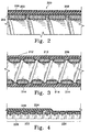
- Figure 2 shows a magnified cross-section of a catheter body or section (200) showing the most basic aspects of one variation of the invention.
- the catheter body or section has a helically wound ribbon (202) and an adhesive (204) on at least an outer portion of the ribbon (202).
- the outer tubing member (206) is polymeric.
- the outer tubing member (206) is produced of a polymer which is heat shrinkable onto the adhesive (204).
- Such polymers include known materials such as polyethylene, polyvinylchloride (PVC), ethylvinylacetate (EVA), polyethylene terephalate (PET), and their mixtures and copolymers.
- PVC polyvinylchloride
- EVA ethylvinylacetate
- PET polyethylene terephalate
- One very useful class of polymers are the thermoplastic elastomers, particularly polyesters.
- the adhesive (204) is desirably a thermoplastic which may be coated onto the inner lumen of the outer tubing member (206), the outer surface of the coil (as wound), the ribbon itself, or may be formed in situ by the use of a mixture of polymers such as polyethylene and EVA, which when heated to a proper temperature exude the EVA onto the ribbon.
- a very highly desirable combination -- from an assembly point of view -- is the use of an thermoplastic adhesive (204) having a softening temperature between the temperature for heat shrinking the outer tubing (206) onto the adhesive (204) and the melting temperature of that outer tubing (206).
- EVA softening/heat shrinking temperature
- an adhesive such as polyester or polyimide.
- the EVA (obviously, with or without other mixed polymers and fillers) is typically extruded into a taking of an appropriate size and thickness and crosslinked to raise the melt temperature of the resultant tubing.
- the tubing is then inflated and, perhaps, stretched to give the included polymer molecular orientation.
- the tubing may then be heat-shrunk onto the catheter.
- a suitable EVA would have significant adhesive properties at about 150°C (300°F).
- the tubing may be of any of a variety of polymers, variously stiff or flexible.
- the outer tubing member (206) may be a polyimide, polyamides such as the Nylons, high density polyethylene (HDPE), polypropylene, polyvinylchloride, various fluoropolymers (for instance: PTFE, FEP, vinylidene fluoride, mixtures, alloys, copolymers, block copolymers, etc.), polysulfones or the like. Blends, alloys, mixtures, copolymers, block copolymers, of these materials are also suitable, if desired.
- the outer tubing member (206) may be a polyurethane, low density polyethylene (LDPE), polyvinylchloride, THV, etc. and other polymers of suitable softness or modulus of elasticity.
- LDPE low density polyethylene
- THV polyvinylchloride
- the inventive catheter design allows the use in the distal portion of the catheter, thin-walled tubing of inherently more slippery polymers, such as PTFE and FEP and their mixtures, which have the benefit of being lubricious but otherwise would have been used in a somewhat greater thickness.
- Production of a good adhesive joint between the helically wound ribbon (202) and the adhesive (204) is not an easy task.
- greater thickness tubing of these polymers results in the resulting catheter section being somewhat stiffer.
- the wall thickness of the outer tubing member (206) may be as thin as 0.013 mm (0.5 mil) and as thick as 0.25 mm (10 mil), depending upon catheter usage, portion of the catheter chosen, polymer choice, and the style of catheter.
- the wall thickness of the tubing member will be between 0.013 and 0.076 mm (0.5 and 3.0 mils). This dimension is obviously only a range and each catheter variation must be carefully designed for the specific purpose to which it is placed.
- each of the polymers discussed herein may be used in conjunction with radiopaque material such as barium sulfate, bismuth trioxide, bismuth carbonate, powdered tungsten, powdered tantalum, or the like so that the location of the various pieces of tubing may be radiographically visualized within the vessel.
- radiopaque material such as barium sulfate, bismuth trioxide, bismuth carbonate, powdered tungsten, powdered tantalum, or the like so that the location of the various pieces of tubing may be radiographically visualized within the vessel.
- the spiral wound ribbon (202) shown in Figure 2 may also be of a variety of different materials. Although metallic ribbons are preferred because of their strength-to-weight ratios, fibrous materials (both synthetic and natural) may also be used. Preferred, because of cost, strength, and ready availability are stainless steels (SS308, SS304, SS318, etc.) and tungsten alloys. In certain applications, particularly smaller diameter catheter sections, more malleable metals and alloys, e.g., gold, platinum, palladium, rhodium, etc. may be used. A platinum alloy with a few percent of tungsten is preferred partially because of its radiopacity.
- the class of alloys known as super-elastic alloys is also a desirable selection.
- Preferred super-elastic alloys include the class of titanium/nickel materials known as nitinol -- alloys discovered by the U.S. Navy Ordnance Laboratory. These materials are discussed at length in U.S. Patent Nos. 3,174,851 to Buehler et al., 3,351,463 to Rozner et al., and 3,753,700 to Harrison et al. These alloys are not readily commercially available in the small ribbons required by the invention described here, but for very high performance catheters are excellent choices.
- Metallic ribbons (202) that are suitable for use in this invention are desirably between 0.013 and 0.038 mm (0.5 mil and 1.5 mil) in thickness and 0.064 and 0.2 mm (2.5 mil and 8.0 mil) in width.
- ribbon I intend to include elongated shapes, the cross-section of which are not square or round and may typically be rectangular, oval or semi-oval. They should have an aspect ratio of at least 0.5 (thickness/width).
- the thickness and width may be somewhat finer, e.g., down to 0.0076 and 0.025 mm (0.30 mil and 1.0 mil), respectively.
- stainless steel ribbons include sizes of 0.025 mm x 0.076 mm (1 mil x 3 mil), 0.05 mm x 0.15 mm (2 mil x 6 mil), and 0.05 mm x 0.2 mm (2 mil x 8 mil).
- Suitable non-metallic ribbons include high performance materials such as those made of polyaramids (e.g., KEVLAR) and carbon fibers.
- non-metallic ribbons in this invention is typically in combination with metallic ribbons to allow "tuning" of the stiffness of the resulting composite.
- a lubricious material such as a silicone or other, perhaps hydrophilic, material such as a polyvinylpyrrolidone composition.
- Typical of the catheter made using this invention are those in the 3 French to 5 French range.
- the inner diameter of such catheters is then 0.5 mm to 1.06 mm (20 mils to 42 mils).
- the inner diameter of those catheters was 0.28 mm to 0.5 mm (11 mils to 20 mils).
- the invention is not limited to such sizes, however.
- Figure 3 shows a variation of the inventive catheter (210) in which the cross-sections of the ribbons (212 & 214) are generally oval rather than rectangular than as shown in Figure 2. Either cross-section is acceptable but the oval section has less of a tendency to bind with guidewires passing through the lumen. Additionally, the Figure 3 variation shows the use of two ribbons (212 & 214) wound side-by-side so to form a single layer of ribbon inside the outer tubing cover (206).
- the dual ribbons may be of the same composition or of differing compositions. They may be of the same size or of differing sizes.
- the number of ribbons may be of any convenient configuration so long as the specific stiffness and kink-resisting criteria are met.
- Figure 4 shows another variation in which catheter sections made according to this invention are used in axial conjunction.
- Section (220) is generally as described in Figures 3 and 4 above, but section (222) is more proximal and enjoys two outer covering layers (224) and (226).
- Covering (224) is simply a proximal extension of the polymeric covering in section (220); polymeric covering (226) is placed directly on the outer surface of the helically-wound coil (228).
- coil (228) may be the same as or different than the coil found in the more distal section (220).
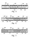
- Other methods for changing the stiffness of various sections of a catheter made using sections of the inventive catheter section are shown in Figures 5, 6, and 7.
- Figure 5 shows a distal section (230) having a helically-wound ribbon (232), an outer polymeric covering (234), and a radiopaque band (236).
- the ribbon (232) is wound in such a fashion that adjacent turns are not contiguous. This allows the distal catheter section (230) to be quite flexible and kink-resistant.
- the intermediate section (238) retains the same outer covering (234), but the pitch of the coil has been narrowed so that the flexibility of the midsection (238) is not as high as was the distal section (230) .
- the most proximal section (240) has no helically-wound ribbon at all, but instead uses a variety of polymeric or other tubing materials to form the stiffest portion of the catheter assembly.
- the outer layer remains as found in the most distal section (230) and the midsection (238).
- the inner layer in this instance is a stiffer material, such as polyimide, polypropylene, or a stainless steel tube, known as a "hypotube".
- Figure 6 shows still another variation of forming the distal section of a catheter assembly which is flexible and yet provides a greater stiffness for other sections of the catheter assembly.
- the intermediate section (242) utilizes double layers of polymeric material, e.g., the outer tubing (234) (discussed above) on the outer surface and an inner tubing of similar or stiffer material (244) in contiguous relationship along the length of the section (242).
- the most proximal section (246) shows only a short overlap between stiff distal tube (248) (perhaps made of the polyimide, polypropylene, nylon, or hypotube materials discussed above) and the outer layer (234). This is a simple arrangement and may be used, for instance, where cost is at a premium.
- Figure 7 shows still a further variation in which the most distal section is a composite of polymeric layers (252) and a braid (254).
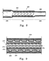
- the composition of the mid and proximal sections are not critical to the invention. They may be of one type or the other depending upon the requirements of the particular application. The most significant of benefits is accrued when, however, the distal section is of the type specified herein. Nevertheless, a variation shown in Figure 8 depicts an instance in which the non-kinking criteria of this invention is applied in a mid-section.
- Catheter (256) uses a distal section having only tubing (260) extending distally of the mid-section (262).
- Midsection (262) comprises both outer tubing (260) and helically-wound ribbon (264) easily held in place according to this invention.
- Proximal section (266) is made stiffer by incorporating multiple layers of tubing, as discussed above.
- the exemplified catheter assemblies in Figures 1, 5, 6, 7, and 8 each utilize three sections, it should be understood that this invention is not so limited.
- the number of sections is selected by the designer when conceptualizing a specific use for a chosen device. Often, the optimum number of sections ends up being three simply because of the physiology of the human body, however, three or more may be involved in this invention.
- the sections additionally need not be of constant stiffness. They may also vary in stiffness--typically as the distal end of a section is approached, the section becomes more flexible.
- Figure 9 shows a short cross-section of a distal end of a vascular catheter (270) in which the outer section comprises an outer cover (206) and a helically-wound ribbon (204) generally as shown in Figure 2.
- a helically-wound coil (204) may be found yet a smaller catheter device covering (272) and a helically-wound coil (274). Again, it is desireable that helically-wound coil (274) and covering (272) be adhesively attached to each other to lessen the chance of any kinking taking place.
- a guidewire (276) which, just as an inner catheter (275), is slidable within outer catheter (270), is slidable within the inner catheter (275).
- a guidewire (276) may have an outside diameter of 0.13 mm to 0.18 mm (5 to 7 mils) in this distal region and the outer diameter of inner catheter (275) may have an outer diameter of 0.32 mm to 0.36 mm (121 ⁇ 2 to 14 mils).
- the most distal portion of the distal section of this catheter (and preferably other sections as well) have a critical bend diameter of no more than 3.5 mm, preferably no more than 2.5 mm, more preferably no more than 1.5 mm, and most preferably no more than 1.0 mm.
- the critical band diameter is also dependent upon the diameter of the catheter section and its components. For instance, I have made 3 French catheter section of the type shown in Figure 2 (of stainless steel ribbon) with critical bond diameters less than 2.5 mm. Similarly, I have made catheter sections such as the inner catheter (275) shown in Figure 9 with an outer diameter of 0.46 mm (0.018") (of platinum-tungsten alloy ribbon) with band diameters less than 1.0 mm.
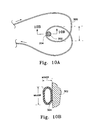
- test we utilize for critical bend diameter determination uses a test shown schematically in Figures 10A and 10B.
- a catheter section (300) is placed between two plates (desirably of plastic or glass or the like for visibility) and often with an optional peg (302) to hold the catheter section (300) loop in place.
- the ends of the catheter are then pulled until a kink appears in the body of the catheter.
- the ratio of the outer diameters (major diameter:minor diameter) as measured at apex (304) reaches a value of 1.5.
- Figure 10B shows the cross section of the catheter sector at (304) and further shows the manner in which the major diameter and the minor diameter are measured.
- region we mean within 15% of the point specified.
- distal region of the distal section would refer to the most distal 15% in length of the distal section.
Landscapes
- Health & Medical Sciences (AREA)
- Life Sciences & Earth Sciences (AREA)
- Biophysics (AREA)
- Pulmonology (AREA)
- Engineering & Computer Science (AREA)
- Anesthesiology (AREA)
- Biomedical Technology (AREA)
- Heart & Thoracic Surgery (AREA)
- Hematology (AREA)
- Animal Behavior & Ethology (AREA)
- General Health & Medical Sciences (AREA)
- Public Health (AREA)
- Veterinary Medicine (AREA)
- Media Introduction/Drainage Providing Device (AREA)
- Materials For Medical Uses (AREA)
- Rigid Pipes And Flexible Pipes (AREA)
Claims (40)
- Katheter mit mindestens einem Abschnitt (200), welcher ein längliches rohrförmiges Element mit einem proximalen und einem distalen Ende und einem innersten Durchgang umfasst, welcher ein sich zwischen diesen Enden erstreckendes Innenlumen ausbildet, mit:dadurch gekennzeichnet, dass die äußere Versteifungsfläche des ersten Bandversteifungsmittels (202, 212, 228, 232) zumindest teilweise mit einem Klebstoffmaterial (204) beschichtet ist und das mindestens eine Schlauchelement (206, 224, 226, 234) an dem ersten Bandversteifungsmittel (202, 212, 228, 232) mittels des Klebstoffmaterials (204) anhaftet.a) einem ersten Bandversteifungsmittel (202, 212, 228, 232) mit einer Breite und einer Dicke, wobei das erste Bandversteifungsmittel (202, 212, 228, 232) spiralförmig gewunden ist, um den innersten Durchgang und eine äußere Versteifungsfläche zu bilden; undb) mindestens einem Schlauchelement (206, 224, 226, 234) außerhalb des und anliegend an dem ersten Bandversteifungsmittels (202, 212, 228, 232),
- Katheter nach Anspruch 1, dadurch gekennzeichnet, dass der Abschnitt einen kritischen Biegungsdurchmesser von nicht mehr als 3,5 mm aufweist.
- Katheter nach Anspruch 1 oder 2, dadurch gekennzeichnet, dass das erste Bandversteifungsmittel (202, 212, 228, 232) metallisch ist.
- Katheter nach Anspruch 3, dadurch gekennzeichnet, dass das erste Bandversteifungsmittel (202, 212, 228, 232) eine superelastische Legierung ist.
- Katheter nach Anspruch 3, dadurch gekennzeichnet, dass das erste Bandversteifungsmittel (202, 212, 228, 232) Nitinol ist.
- Katheter nach Anspruch 3, dadurch gekennzeichnet, dass das erste Bandversteifungsmittel (202, 212, 228, 232) Edelstahl ist.
- Katheter nach Anspruch 3, dadurch gekennzeichnet, dass das erste Bandversteifungsmittel (202, 212, 228, 232) eine Platinwolframlegierung ist.
- Katheterabschnitt nach einem der vorstehenden Ansprüche, dadurch gekennzeichnet, dass das Schlauchelement (206, 224, 226, 234) ohne wesentliche Verschlechterung seiner physikalischen Eigenschaften durch Bestrahlung sterilisierbar ist.
- Katheter nach einem der vorstehenden Ansprüche, dadurch gekennzeichnet, dass der Abschnitt zusätzlich mindestens ein zweites Bandversteifungsmittel (214) der gleichen Händigkeit umfasst, das koaxial zwischen den spiralförmigen Windungen des ersten Bandversteifungsmittels (212) gewunden ist.
- Katheter nach Anspruch 9, dadurch gekennzeichnet, dass das zweite Bandversteifungsmittel (214) ein Band mit einer Dicke zwischen 0,19 mm und 0,064 mm (0,75 mil bzw. 2,5 mil) und einer Dicke zwischen 0,064 mm und 0,203 mm (2,5 bzw. 8,0 mil) umfasst.
- Katheter nach einem der Ansprüche 1 bis 8, bei welchem das erste Bandversteifungsmittel (232) eine Steigung aufweist, welche zwischen dem proximalen Ende und dem distalen Ende variiert.
- Katheter nach einem der vorstehenden Ansprüche, bei welchem das längliche rohrförmige Element mindestens einen Bereich variabler Steifheit zwischen dem proximalen Ende und dem distalen Ende aufweist.
- Katheter nach einem der vorstehenden Ansprüche, bei welchem das erste Bandversteifungsmittel (202, 212, 228, 232) ein Band mit einer Dicke zwischen 0,013 mm und 0,064 mm (0,5 mil bzw. 2,5 mil) und einer Dicke zwischen 0,064 mm und 0,203 mm (2,5 bzw. 8,0 mil) aufweist.
- Katheter nach einem der vorstehenden Ansprüche, dadurch gekennzeichnet, dass das Schlauchelement (206, 224, 226, 234) ein Polymer enthält.
- Katheter nach Anspruch 14, dadurch gekennzeichnet, dass das Schlauchelement (206, 224, 226, 234) ein Polymer enthält, das auf das erste Bandversteifungsmittel aufgeschrumpft werden kann.
- Katheter nach Anspruch 15, dadurch gekennzeichnet, dass das Schlauchelement (206, 224, 226, 234) ein aus Polyethylen, Ethylvinylacetat, Polyethylenterephthalat, Polyvinylchlorid und deren Mischungen und Copolymeren gewähltes Polymer enthält.
- Katheter nach Anspruch 16, dadurch gekennzeichnet, dass das Schlauchelement (206, 224, 226, 234) EVA umfasst.
- Katheter nach einem der Ansprüche 15 bis 17, dadurch gekennzeichnet, dass das Klebstoffmaterial (204) eine Erweichungstemperatur über der Aufschrumpftemperatur des Schlauchelements (206, 224, 226, 234), aber unter der Schmelztemperatur des Schlauchelements (206, 224, 226, 234) aufweist.
- Katheter nach einem der vorstehenden Ansprüche, dadurch gekennzeichnet, dass das Klebstoffmaterial (204) auf eine Innenfläche des Schlauchelements (206, 224, 226, 234) gegeben wurde.
- Katheter nach einem der Ansprüche 1 bis 18, dadurch gekennzeichnet, dass das Klebstoffmaterial (204) während der Montage des Katheterabschnitts in situ aus dem Schlauchelement (206, 224, 226, 234) ausgeschieden wird.
- Katheter nach einem der Ansprüche 1 bis 18, dadurch gekennzeichnet, dass das Klebstoffmaterial (204) mindestens auf die Außenfläche des gewundenen ersten Bandversteifungsmittels (202, 212, 228, 232) gegeben wurde.
- Katheter nach einem der vorstehenden Ansprüche, dadurch gekennzeichnet, dass das Klebstoffmaterial (204) aus Polyimiden und Polyestern gewählt wird.
- Katheter nach Anspruch 22, dadurch gekennzeichnet, dass das Klebstoffmaterial (204) ein Polyester ist.
- Katheter nach einem der vorstehenden Ansprüche, dadurch gekennzeichnet, dass das Schlauchelement (206, 224, 226, 234) strahlenundurchlässig ist.
- Katheter nach einem der Ansprüche 1 bis 8, dadurch gekennzeichnet, dass benachbarte Windungen in dem ersten Bandversteifungsmittel (232) anliegend sind.
- Katheter nach einem der Ansprüche 1 bis 24, dadurch gekennzeichnet, dass benachbarte Windungen in dem ersten Bandversteifungsmittel (232) nicht anliegend sind.
- Katheter nach einem der vorstehenden Ansprüche, dadurch gekennzeichnet, dass der Abschnitt weiterhin eine zweite Abdeckung (208, 224) außerhalb des Schlauchelements umfasst.
- Katheter nach Anspruch 27, dadurch gekennzeichnet, dass die zweite Abdeckung (208, 224) ein Material gewählt aus Polyimid, Polyamiden, Polyethylen, Polypropylen, Polyvinylchlorid, Polyurethan, Fluorpolymeren einschließlich PTFE, FEP, Vinylidenfluorid und deren Mischungen, Legierungen, Copolymeren und Blockcopolymeren oder Polysulfonen enthält.
- Katheter nach einem der vorstehenden Ansprüche, welcher weiterhin einen entnehmbaren, schiebbaren Führungsdraht (276) enthält, welcher in dem Abschnitt und in schiebbarer Beziehung hierzu platziert ist.
- Katheter nach einem der Ansprüche 1 bis 28, welcher weiterhin einen Innenkatheter (275) umfasst, welcher entnehmbar, schiebbar und zusammenschiebbar im Inneren des Abschnitts und in schiebbarer Beziehung hierzu platziert ist.
- Katheter nach Anspruch 30, welcher weiterhin einen Führungsdraht (276) umfasst, welcher im Inneren des Innenkatheters (275) und in schiebbarer Position hierzu platziert ist.
- Katheter nach Anspruch 1 mit:(a) einem proximalen Abschnitt (106, 240, 242)(b) einem distalen Abschnitt (102, 230), welcher biegsamer als der proximale Abschnitt (106) ist und den das erste Bandversteifungsmittel (202, 212, 228, 232) und mindestens ein Schlauchelement (206, 224, 226, 234) umfassenden Abschnitt bildet.
- Katheter nach Anspruch 32, dadurch gekennzeichnet, dass der distale Abschnitt (102) einen kritischen Biegungsdurchmesser von nicht mehr als 3,5 mm aufweist.
- Katheter nach Anspruch 32 oder Anspruch 33, dadurch gekennzeichnet, dass der proximale Abschnitt (222) eine zweite Abdeckung (226) umfasst, welche ein zwischen einer proximalen Verlängerung des Schlauchelements (224) und dem ersten Bandversteifungsmittel (228) angeordnetes proximales Abdeckmaterial umfasst.
- Katheter nach einem der Ansprüche 32 bis 34, welcher weiterhin mindestens einen Zwischenabschnitt (104, 238) mit einer Biegsamkeit zwischen der Biegsamkeit des distalen Abschnitts (102, 230) und der des proximalen Abschnitts (106, 240, 242) umfasst, wobei der Zwischenabschnitt (104, 238) einen Durchgang zwischen dem proximalen Abschnitt (106, 240, 242) und dem distalen Abschnitt (102, 230) ausbildet.
- Katheter nach Anspruch 35, dadurch gekennzeichnet, dass der mindestens eine Zwischenabschnitt (238) aus einer Verlängerung des Schlauchelements (206, 224, 226, 234) und dem ersten Bandversteifungsmittel (202, 212, 228, 232) besteht.
- Katheter nach einem der Ansprüche 32 bis 36, bei welchem der proximale Abschnitt (106) des Katheters weiterhin ein zweites Bandversteifungsmittel (214) der gleichen Händigkeit umfasst, welches koaxial zwischen den spiralförmigen Windungen des ersten Bandversteifungsmittels (212) gewunden ist.
- Katheter nach einem der Ansprüche 32 bis 37, bei welchem der Zwischenabschnitt (104) des Katheters weiterhin ein zweites Bandversteifungsmittel (214) der gleichen Händigkeit umfasst, welches koaxial zwischen den spiralförmigen Windungen des ersten Bandversteifungsmittels (212) gewunden ist.
- Katheter nach Anspruch 35, bei welchem der proximale Abschnitt (106) des Katheters ein metallisches Hypotube umfasst.
- Katheter nach Anspruch 35, bei welchem der proximale Abschnitt (106) des Katheters einen Polymerschlauch umfasst, welcher proximal am Schlauchelement (206, 224, 226, 234) und dem ersten Bandversteifungsmittel (202, 212, 228, 232) anliegt.
Applications Claiming Priority (2)
| Application Number | Priority Date | Filing Date | Title |
|---|---|---|---|
| US338018 | 1994-11-10 | ||
| US08/338,018 US5658264A (en) | 1994-11-10 | 1994-11-10 | High performance spiral-wound catheter |
Publications (3)
| Publication Number | Publication Date |
|---|---|
| EP0715863A2 EP0715863A2 (de) | 1996-06-12 |
| EP0715863A3 EP0715863A3 (de) | 1996-12-04 |
| EP0715863B1 true EP0715863B1 (de) | 2004-02-04 |
Family
ID=23323049
Family Applications (1)
| Application Number | Title | Priority Date | Filing Date |
|---|---|---|---|
| EP95308049A Expired - Lifetime EP0715863B1 (de) | 1994-11-10 | 1995-11-10 | Katheter |
Country Status (9)
| Country | Link |
|---|---|
| US (4) | US5658264A (de) |
| EP (1) | EP0715863B1 (de) |
| JP (3) | JP3224501B2 (de) |
| AT (1) | ATE258814T1 (de) |
| AU (1) | AU3780495A (de) |
| CA (1) | CA2162554C (de) |
| DE (1) | DE69532521T2 (de) |
| ES (1) | ES2215171T3 (de) |
| IL (1) | IL115928A0 (de) |
Families Citing this family (243)
| Publication number | Priority date | Publication date | Assignee | Title |
|---|---|---|---|---|
| US6482171B1 (en) * | 1991-07-16 | 2002-11-19 | Heartport, Inc. | Multi-lumen catheter |
| US6659977B2 (en) | 1993-10-27 | 2003-12-09 | Schneider (Europe) A.G. | Multilayer interventional catheter |
| US6824553B1 (en) | 1995-04-28 | 2004-11-30 | Target Therapeutics, Inc. | High performance braided catheter |
| US20030069522A1 (en) | 1995-12-07 | 2003-04-10 | Jacobsen Stephen J. | Slotted medical device |
| US6165166A (en) | 1997-04-25 | 2000-12-26 | Schneider (Usa) Inc. | Trilayer, extruded medical tubing and medical devices incorporating such tubing |
| US6183420B1 (en) * | 1997-06-20 | 2001-02-06 | Medtronic Ave, Inc. | Variable stiffness angioplasty guide wire |
| US6077258A (en) | 1997-10-03 | 2000-06-20 | Scimed Life Systems, Inc. | Braided angiography catheter having full length radiopacity and controlled flexibility |
| US6074407A (en) * | 1997-10-14 | 2000-06-13 | Target Therapeutics, Inc. | Delivery catheter for occlusive implants |
| US6273876B1 (en) | 1997-12-05 | 2001-08-14 | Intratherapeutics, Inc. | Catheter segments having circumferential supports with axial projection |
| US6033394A (en) * | 1997-12-05 | 2000-03-07 | Intratherapeutics, Inc. | Catheter support structure |
| US6110164A (en) * | 1997-12-05 | 2000-08-29 | Intratherapeutics, Inc. | Guideless catheter segment |
| US6402720B1 (en) * | 1997-12-22 | 2002-06-11 | Cordis Corporation | Balloon catheter with elongated flexible tip |
| US6036670A (en) * | 1997-12-23 | 2000-03-14 | Cordis Corporation | Coiled transition balloon catheter, assembly and procedure |
| US6130406A (en) * | 1998-01-08 | 2000-10-10 | Adam Spence Corporation | Method for forming a medical tubing device |
| US6179827B1 (en) | 1998-03-16 | 2001-01-30 | Chase Medical | Catheter having integral expandable/collapsible lumen |
| DE19816986C1 (de) * | 1998-04-17 | 1999-08-05 | Rehau Ag & Co | Verfahren zur Herstellung armierter, medizinischer Schläuche |
| US6702972B1 (en) * | 1998-06-09 | 2004-03-09 | Diametrics Medical Limited | Method of making a kink-resistant catheter |
| US6368316B1 (en) | 1998-06-11 | 2002-04-09 | Target Therapeutics, Inc. | Catheter with composite stiffener |
| US6126650A (en) * | 1998-06-30 | 2000-10-03 | Cordis Corporation | Flow directed catheter having radiopaque strain relief segment |
| US6152911A (en) * | 1998-08-27 | 2000-11-28 | Chase Medical, Inc. | Venous return catheter having multiple helical support members |
| US6340368B1 (en) | 1998-10-23 | 2002-01-22 | Medtronic Inc. | Implantable device with radiopaque ends |
| US6102890A (en) * | 1998-10-23 | 2000-08-15 | Scimed Life Systems, Inc. | Catheter having improved proximal shaft design |
| US6068621A (en) * | 1998-11-20 | 2000-05-30 | Embol X, Inc. | Articulating cannula |
| US6361557B1 (en) | 1999-02-05 | 2002-03-26 | Medtronic Ave, Inc. | Staplebutton radiopaque marker |
| US6319244B2 (en) * | 1999-03-16 | 2001-11-20 | Chase Medical, L.P. | Catheter with flexible and rigid reinforcements |
| US6648854B1 (en) | 1999-05-14 | 2003-11-18 | Scimed Life Systems, Inc. | Single lumen balloon-tipped micro catheter with reinforced shaft |
| US6210396B1 (en) | 1999-06-24 | 2001-04-03 | Medtronic, Inc. | Guiding catheter with tungsten loaded band |
| US6280433B1 (en) * | 1999-09-09 | 2001-08-28 | Medtronic, Inc. | Introducer system |
| EP1196213B1 (de) * | 1999-07-06 | 2005-11-02 | Medtronic, Inc. | System zum einführen von kathetern |
| US6508804B2 (en) | 1999-07-28 | 2003-01-21 | Scimed Life Systems, Inc. | Catheter having continuous lattice and coil reinforcement |
| US6689120B1 (en) * | 1999-08-06 | 2004-02-10 | Boston Scientific Scimed, Inc. | Reduced profile delivery system |
| US6569128B1 (en) * | 1999-09-22 | 2003-05-27 | Advanced Infusion Corporation | Catheter with adjustable flow restrictor |
| US7118551B1 (en) | 1999-12-22 | 2006-10-10 | Advanced Cardiovascular Systems, Inc. | Non-metal reinforcing mandrel |
| US6648874B2 (en) | 2000-02-28 | 2003-11-18 | Scimed Life Systems, Inc. | Guide catheter with lubricious inner liner |
| US10092313B2 (en) * | 2000-04-05 | 2018-10-09 | Boston Scientific Limited | Medical sealed tubular structures |
| JP2003530165A (ja) * | 2000-04-11 | 2003-10-14 | サイムド ライフ システムズ, インコーポレイテッド | 強化保持構造体 |
| US6663648B1 (en) | 2000-06-15 | 2003-12-16 | Cordis Corporation | Balloon catheter with floating stiffener, and procedure |
| AU2001273446B2 (en) * | 2000-07-14 | 2006-03-30 | Cook Medical Technologies Llc | Medical device with braid and coil |
| US20040073154A1 (en) * | 2000-07-25 | 2004-04-15 | Borgesen Svend Erik | Ventricle drain |
| GB0019107D0 (en) * | 2000-08-03 | 2000-09-27 | Ranier Ltd | Balloon-free uninary catheter |
| US6669886B1 (en) * | 2000-08-03 | 2003-12-30 | Scimed Life Systems, Inc. | Reinforced catheter and method of manufacture |
| US6508806B1 (en) * | 2000-12-13 | 2003-01-21 | Advanced Cardiovascular Systems, Inc. | Catheter with multi-layer wire reinforced wall construction |
| US20030060731A1 (en) * | 2001-01-26 | 2003-03-27 | Fleischhacker Mark G. | Non-metallic guide wire |
| US7422579B2 (en) * | 2001-05-01 | 2008-09-09 | St. Jude Medical Cardiology Divison, Inc. | Emboli protection devices and related methods of use |
| JP3641221B2 (ja) * | 2001-05-14 | 2005-04-20 | 東芝テリー株式会社 | パイプガイドの製造方法 |
| WO2003004086A2 (en) | 2001-07-05 | 2003-01-16 | Precision Vascular Systems, Inc. | Troqueable soft tip medical device and method of usage |
| US7071898B2 (en) * | 2002-07-18 | 2006-07-04 | Information Decision Technologies, Llc | Method for using a wireless motorized camera mount for tracking in augmented reality |
| US6863678B2 (en) * | 2001-09-19 | 2005-03-08 | Advanced Cardiovascular Systems, Inc. | Catheter with a multilayered shaft section having a polyimide layer |
| US6783527B2 (en) | 2001-10-30 | 2004-08-31 | Sdgi Holdings, Inc. | Flexible spinal stabilization system and method |
| US20030093060A1 (en) * | 2001-11-09 | 2003-05-15 | Vadnais Technologies Corporation | Catheter assembly |
| US6866655B2 (en) | 2002-04-23 | 2005-03-15 | Scimed Life Systems, Inc. | Medical device with atraumatic tip |
| US6929766B2 (en) * | 2002-06-14 | 2005-08-16 | Edwards Lifesciences Corporation | Dispense molding method and apparatus for manufacturing cannulae |
| US6936210B2 (en) * | 2002-06-14 | 2005-08-30 | Edwards Lifesciences Corporation | Wave molding method and apparatus for manufacturing cannulae |
| US7878984B2 (en) | 2002-07-25 | 2011-02-01 | Boston Scientific Scimed, Inc. | Medical device for navigation through anatomy and method of making same |
| US7914467B2 (en) | 2002-07-25 | 2011-03-29 | Boston Scientific Scimed, Inc. | Tubular member having tapered transition for use in a medical device |
| US20040045645A1 (en) * | 2002-09-10 | 2004-03-11 | Scimed Life Systems, Inc. | Shaped reinforcing member for medical device and method for making the same |
| US8377035B2 (en) | 2003-01-17 | 2013-02-19 | Boston Scientific Scimed, Inc. | Unbalanced reinforcement members for medical device |
| JP3971320B2 (ja) * | 2003-02-17 | 2007-09-05 | 修 加藤 | カテーテル |
| US7169118B2 (en) | 2003-02-26 | 2007-01-30 | Scimed Life Systems, Inc. | Elongate medical device with distal cap |
| US6896671B2 (en) * | 2003-03-12 | 2005-05-24 | Arrow International, Inc. | Catheter with limited longitudinal extension |
| US7001369B2 (en) | 2003-03-27 | 2006-02-21 | Scimed Life Systems, Inc. | Medical device |
| US20040199052A1 (en) | 2003-04-01 | 2004-10-07 | Scimed Life Systems, Inc. | Endoscopic imaging system |
| US7201745B2 (en) * | 2003-05-13 | 2007-04-10 | Boston Scientific Scimed, Inc. | Anti-infective central venous catheter with diffusion barrier layer |
| US8109922B2 (en) * | 2003-06-12 | 2012-02-07 | Cordis Corporation | Orifice device having multiple channels and multiple layers for drug delivery |
| US8491571B2 (en) * | 2003-06-12 | 2013-07-23 | Cordis Corporation | Orifice device having multiple channels with varying flow rates for drug delivery |
| US7108762B2 (en) * | 2003-06-12 | 2006-09-19 | Cordis Corporation | Method for manufacturing an orifice mechanism capable of low fluid flow rates |
| US7211076B2 (en) | 2003-06-12 | 2007-05-01 | Cordis Corporation | Medical device for fluid delivery having low fluid flow rate |
| US7678103B2 (en) * | 2003-06-12 | 2010-03-16 | Cordis Corporation | Orifice device for delivering drugs at low fluid flow rates |
| JP2005058304A (ja) * | 2003-08-08 | 2005-03-10 | Terumo Corp | イントロデューサーシース |
| US7824392B2 (en) | 2003-08-20 | 2010-11-02 | Boston Scientific Scimed, Inc. | Catheter with thin-walled braid |
| US7615043B2 (en) | 2003-08-20 | 2009-11-10 | Boston Scientific Scimed, Inc. | Medical device incorporating a polymer blend |
| JP4713478B2 (ja) * | 2003-09-02 | 2011-06-29 | アボット・ラボラトリーズ | 医療器具の送出システム |
| US7744587B2 (en) * | 2003-09-22 | 2010-06-29 | Boston Scientific Scimed, Inc. | Surface modified reinforcing member for medical device and method for making same |
| US7338495B2 (en) * | 2003-10-22 | 2008-03-04 | Medtronic Xomed, Inc. | Angled tissue cutting instruments having flexible inner tubular members of tube and sleeve construction |
| US7955313B2 (en) * | 2003-12-17 | 2011-06-07 | Boston Scientific Scimed, Inc. | Composite catheter braid |
| US7824345B2 (en) | 2003-12-22 | 2010-11-02 | Boston Scientific Scimed, Inc. | Medical device with push force limiter |
| US7844344B2 (en) | 2004-03-30 | 2010-11-30 | Medtronic, Inc. | MRI-safe implantable lead |
| US8177760B2 (en) | 2004-05-12 | 2012-05-15 | C. R. Bard, Inc. | Valved connector |
| US20050273076A1 (en) * | 2004-06-07 | 2005-12-08 | C.R. Bard, Inc. | Subcutaneous infusion devices |
| US8500785B2 (en) * | 2004-07-13 | 2013-08-06 | Boston Scientific Scimed, Inc. | Catheter |
| WO2006031874A1 (en) * | 2004-09-14 | 2006-03-23 | William A. Cook Australia Pty. Ltd. | Large diameter sheath |
| US20060089569A1 (en) * | 2004-10-26 | 2006-04-27 | Soukup Thomas M | Articulator with adjustable stiffness distal portion |
| AU2005302021A1 (en) * | 2004-11-01 | 2006-05-11 | Applied Medical Resources Corporation | Longitudinal sheath enforcement |
| US20060111649A1 (en) * | 2004-11-19 | 2006-05-25 | Scimed Life Systems, Inc. | Catheter having improved torque response and curve retention |
| US7815599B2 (en) | 2004-12-10 | 2010-10-19 | Boston Scientific Scimed, Inc. | Catheter having an ultra soft tip and methods for making the same |
| US20060184105A1 (en) * | 2005-02-15 | 2006-08-17 | Townsend Gregory L | Thin wall catheter and method of placing same |
| US20060188679A1 (en) * | 2005-02-24 | 2006-08-24 | Pedroso Pedro D | Fluorinated material for medical devices such as catheters |
| WO2007004076A2 (en) | 2005-05-09 | 2007-01-11 | Angiomed Gmbh & Co. Medizintechnik Kg | Implant delevery device |
| JP2006333966A (ja) * | 2005-05-31 | 2006-12-14 | Kaneka Corp | 塞栓コイルデリバリー用カテーテルチューブ |
| US20060282112A1 (en) * | 2005-06-09 | 2006-12-14 | Stephen Griffin | Method and apparatus for enhanced electrolytic detachment |
| US9445784B2 (en) | 2005-09-22 | 2016-09-20 | Boston Scientific Scimed, Inc | Intravascular ultrasound catheter |
| US7850623B2 (en) | 2005-10-27 | 2010-12-14 | Boston Scientific Scimed, Inc. | Elongate medical device with continuous reinforcement member |
| US7892186B2 (en) * | 2005-12-09 | 2011-02-22 | Heraeus Materials S.A. | Handle and articulator system and method |
| AU2007223403B2 (en) | 2006-03-01 | 2013-03-28 | Applied Medical Resources Corporation | Gas insufflation suction and irrigation medical tubing |
| US7906066B2 (en) | 2006-06-30 | 2011-03-15 | Abbott Cardiovascular Systems, Inc. | Method of making a balloon catheter shaft having high strength and flexibility |
| US8382738B2 (en) | 2006-06-30 | 2013-02-26 | Abbott Cardiovascular Systems, Inc. | Balloon catheter tapered shaft having high strength and flexibility and method of making same |
| US20080097296A1 (en) * | 2006-08-16 | 2008-04-24 | Boston Scientific Scimed, Inc. | Removable hub assembly for medical device |
| US7674253B2 (en) * | 2006-08-18 | 2010-03-09 | Kensey Nash Corporation | Catheter for conducting a procedure within a lumen, duct or organ of a living being |
| US8551020B2 (en) | 2006-09-13 | 2013-10-08 | Boston Scientific Scimed, Inc. | Crossing guidewire |
| US20160051801A1 (en) * | 2014-08-19 | 2016-02-25 | Minnetronix, Inc. | Devices and Systems for Access and Navigation of Cerebrospinal Fluid Space |
| US7981091B2 (en) * | 2006-10-24 | 2011-07-19 | Vascular Solutions, Inc. | Small diameter intravascular catheter with screw tip and limited torsional displacement |
| US8287519B2 (en) * | 2006-10-27 | 2012-10-16 | Smith Tech Innovations, Llc | Self-cleansing bladder drainage catheter |
| US8556914B2 (en) | 2006-12-15 | 2013-10-15 | Boston Scientific Scimed, Inc. | Medical device including structure for crossing an occlusion in a vessel |
| US9114229B2 (en) | 2006-12-29 | 2015-08-25 | St. Jude Medical, Af Division, Inc. | Dual braid reinforcement deflectable device |
| US9950141B2 (en) | 2006-12-29 | 2018-04-24 | St. Jude Medical, Atrial Fibrillation Division, Inc. | Dual braid reinforcement deflectable device (sheath or catheter) |
| US8182466B2 (en) * | 2006-12-29 | 2012-05-22 | St. Jude Medical, Atrial Fibrillation Division, Inc. | Dual braided catheter shaft |
| US10278682B2 (en) * | 2007-01-30 | 2019-05-07 | Loma Vista Medical, Inc. | Sheaths for medical devices |
| US8088097B2 (en) | 2007-11-21 | 2012-01-03 | Glumetrics, Inc. | Use of an equilibrium intravascular sensor to achieve tight glycemic control |
| EP2120680A2 (de) | 2007-02-06 | 2009-11-25 | Glumetrics, Inc. | Optische systeme und verfahren zur ratiometrischen messung der blutzuckerkonzentration |
| US9044593B2 (en) | 2007-02-14 | 2015-06-02 | Medtronic, Inc. | Discontinuous conductive filler polymer-matrix composites for electromagnetic shielding |
| JP4266042B2 (ja) * | 2007-02-21 | 2009-05-20 | 株式会社シンテック | 線状部材、線状部材の製造方法および装身具 |
| US8483842B2 (en) | 2007-04-25 | 2013-07-09 | Medtronic, Inc. | Lead or lead extension having a conductive body and conductive body contact |
| CA2686065A1 (en) | 2007-05-10 | 2008-11-20 | Glumetrics, Inc. | Equilibrium non-consuming fluorescence sensor for real time intravascular glucose measurement |
| US8858490B2 (en) | 2007-07-18 | 2014-10-14 | Silk Road Medical, Inc. | Systems and methods for treating a carotid artery |
| US8157760B2 (en) | 2007-07-18 | 2012-04-17 | Silk Road Medical, Inc. | Methods and systems for establishing retrograde carotid arterial blood flow |
| US8409114B2 (en) | 2007-08-02 | 2013-04-02 | Boston Scientific Scimed, Inc. | Composite elongate medical device including distal tubular member |
| US8105246B2 (en) | 2007-08-03 | 2012-01-31 | Boston Scientific Scimed, Inc. | Elongate medical device having enhanced torque and methods thereof |
| US8821477B2 (en) | 2007-08-06 | 2014-09-02 | Boston Scientific Scimed, Inc. | Alternative micromachined structures |
| US9808595B2 (en) | 2007-08-07 | 2017-11-07 | Boston Scientific Scimed, Inc | Microfabricated catheter with improved bonding structure |
| US8114144B2 (en) * | 2007-10-17 | 2012-02-14 | Abbott Cardiovascular Systems Inc. | Rapid-exchange retractable sheath self-expanding delivery system with incompressible inner member and flexible distal assembly |
| US7841994B2 (en) | 2007-11-02 | 2010-11-30 | Boston Scientific Scimed, Inc. | Medical device for crossing an occlusion in a vessel |
| US20090157047A1 (en) * | 2007-12-13 | 2009-06-18 | Boston Scientific Scimed, Inc. | Medical device coatings and methods of forming such coatings |
| US8403885B2 (en) | 2007-12-17 | 2013-03-26 | Abbott Cardiovascular Systems Inc. | Catheter having transitioning shaft segments |
| EP2234663A1 (de) * | 2007-12-19 | 2010-10-06 | Boston Scientific Scimed, Inc. | Struktur zur verwendung als teil einer medizinischen vorrichtung |
| EP2249691B1 (de) * | 2008-01-24 | 2013-07-03 | Boston Scientific Scimed, Inc. | Struktur zur verwendung als teil einer medizinischen vorrichtung |
| WO2009100210A1 (en) | 2008-02-05 | 2009-08-13 | Silk Road Medical, Inc. | Interventional catheter system and methods |
| US9037263B2 (en) | 2008-03-12 | 2015-05-19 | Medtronic, Inc. | System and method for implantable medical device lead shielding |
| US20090240109A1 (en) * | 2008-03-24 | 2009-09-24 | Boston Scientific Scimed, Inc. | Flexible endoscope with core member |
| US8376961B2 (en) | 2008-04-07 | 2013-02-19 | Boston Scientific Scimed, Inc. | Micromachined composite guidewire structure with anisotropic bending properties |
| WO2009129186A2 (en) | 2008-04-17 | 2009-10-22 | Glumetrics, Inc. | Sensor for percutaneous intravascular deployment without an indwelling cannula |
| US9750625B2 (en) * | 2008-06-11 | 2017-09-05 | C.R. Bard, Inc. | Catheter delivery device |
| GB0810749D0 (en) | 2008-06-11 | 2008-07-16 | Angiomed Ag | Catherter delivery device |
| US20090318892A1 (en) * | 2008-06-20 | 2009-12-24 | Maria Aboytes | Removable Core Implant Delivery Catheter |
| US8206373B2 (en) * | 2008-07-01 | 2012-06-26 | Boston Scientific Scimed, Inc. | Medical device including braid with coated portion |
| CA2734738C (en) | 2008-08-18 | 2019-05-07 | Productive Research LLC. | Formable light weight composites |
| US20100049167A1 (en) * | 2008-08-20 | 2010-02-25 | Cook Incorporated | Introducer sheath having reinforced distal taper |
| US20100048758A1 (en) * | 2008-08-22 | 2010-02-25 | Boston Scientific Scimed, Inc. | Lubricious coating composition for devices |
| US8535243B2 (en) | 2008-09-10 | 2013-09-17 | Boston Scientific Scimed, Inc. | Medical devices and tapered tubular members for use in medical devices |
| US8216498B2 (en) | 2008-09-10 | 2012-07-10 | Boston Scientific Scimed, Inc. | Catheter having a coextruded fluoropolymer layer |
| US8162891B2 (en) | 2008-11-26 | 2012-04-24 | Revascular Therapeutics, Inc. | Delivery and exchange catheter for storing guidewire |
| US8052638B2 (en) | 2008-11-26 | 2011-11-08 | Abbott Cardiovascular Systems, Inc. | Robust multi-layer balloon |
| US8444608B2 (en) | 2008-11-26 | 2013-05-21 | Abbott Cardivascular Systems, Inc. | Robust catheter tubing |
| WO2010068814A1 (en) | 2008-12-10 | 2010-06-17 | Boston Scientific Scimed, Inc. | Introducer sheath with an embolic coil device and methods for making the same |
| US8795254B2 (en) | 2008-12-10 | 2014-08-05 | Boston Scientific Scimed, Inc. | Medical devices with a slotted tubular member having improved stress distribution |
| US20110245807A1 (en) * | 2008-12-11 | 2011-10-06 | Kaneka Corporation | Medical Tube |
| JP2012513292A (ja) | 2008-12-23 | 2012-06-14 | シルク・ロード・メディカル・インコーポレイテッド | 急性虚血性脳卒中の治療方法及び治療システム |
| US20100204684A1 (en) * | 2009-01-13 | 2010-08-12 | Garrison Michi E | Methods and systems for performing neurointerventional procedures |
| US8864744B2 (en) | 2009-02-25 | 2014-10-21 | St. Jude Medical, Atrial Fibrillation Division, Inc. | Medical device having laminate-coated braid assembly |
| WO2010126877A1 (en) | 2009-04-30 | 2010-11-04 | Medtronic, Inc. | Shielding an implantable medical lead |
| JP5755835B2 (ja) * | 2009-09-29 | 2015-07-29 | 富士フイルム株式会社 | 内視鏡用可撓管及びその製造方法 |
| US20110077477A1 (en) | 2009-09-30 | 2011-03-31 | Glumetrics, Inc. | Sensors with thromboresistant coating |
| US8467843B2 (en) | 2009-11-04 | 2013-06-18 | Glumetrics, Inc. | Optical sensor configuration for ratiometric correction of blood glucose measurement |
| DE102009052688A1 (de) * | 2009-11-11 | 2011-05-12 | Invendo Medical Gmbh | Endoskopschaft aus einem Verbundschlauch |
| US8137293B2 (en) | 2009-11-17 | 2012-03-20 | Boston Scientific Scimed, Inc. | Guidewires including a porous nickel-titanium alloy |
| KR101774911B1 (ko) | 2009-12-28 | 2017-09-05 | 프로덕티브 리서치 엘엘씨 | 복합 재료의 용접 공정 및 그로부터 제조된 제품 |
| US9415568B2 (en) | 2010-02-15 | 2016-08-16 | Productive Research Llc | Formable light weight composite material systems and methods |
| US20110238041A1 (en) * | 2010-03-24 | 2011-09-29 | Chestnut Medical Technologies, Inc. | Variable flexibility catheter |
| US8551021B2 (en) | 2010-03-31 | 2013-10-08 | Boston Scientific Scimed, Inc. | Guidewire with an improved flexural rigidity profile |
| US8034045B1 (en) * | 2010-05-05 | 2011-10-11 | Cook Medical Technologies Llc | Flexible sheath |
| WO2012039199A1 (ja) * | 2010-09-23 | 2012-03-29 | オリンパスメディカルシステムズ株式会社 | 湾曲カテーテル |
| CN103648574B (zh) | 2010-10-04 | 2016-08-10 | 科维蒂恩有限合伙公司 | 远侧进入抽吸导引导管 |
| WO2012106628A1 (en) | 2011-02-04 | 2012-08-09 | Boston Scientific Scimed, Inc. | Guidewires and methods for making and using the same |
| US8591495B2 (en) * | 2011-02-23 | 2013-11-26 | Fischell Innovations, Llc | Introducer sheath with thin-walled shaft |
| EP2688736B1 (de) | 2011-03-22 | 2017-11-29 | Applied Medical Resources Corporation | Verfahren zur herstellung eines medizinischen tubus mit drainagelöchern |
| US9072874B2 (en) | 2011-05-13 | 2015-07-07 | Boston Scientific Scimed, Inc. | Medical devices with a heat transfer region and a heat sink region and methods for manufacturing medical devices |
| WO2012162661A1 (en) | 2011-05-26 | 2012-11-29 | Abbott Cardiovascular Systems Inc. | Through tip for a catheter |
| WO2012176189A1 (en) * | 2011-06-21 | 2012-12-27 | Dr. Eyal Bressler Ltd. | A catheter with an enhanced pushability |
| US10130789B2 (en) | 2011-06-30 | 2018-11-20 | Covidien Lp | Distal access aspiration guide catheter |
| JP2014521462A (ja) | 2011-08-05 | 2014-08-28 | シルク・ロード・メディカル・インコーポレイテッド | 急性虚血性脳卒中を治療するための方法及びシステム |
| US10779855B2 (en) | 2011-08-05 | 2020-09-22 | Route 92 Medical, Inc. | Methods and systems for treatment of acute ischemic stroke |
| US8870860B2 (en) | 2011-08-09 | 2014-10-28 | Covidien Lp | Microwave antenna having a coaxial cable with an adjustable outer conductor configuration |
| EP2572749B1 (de) * | 2011-09-23 | 2022-04-27 | Covidien LP | Ballonführungskatheter für distalen Zugang |
| JP5891770B2 (ja) * | 2011-12-19 | 2016-03-23 | 住友ベークライト株式会社 | 医療機器、および医療機器の製造方法 |
| JP5891789B2 (ja) * | 2011-12-28 | 2016-03-23 | 住友ベークライト株式会社 | 医療機器、および医療機器の製造方法 |
| US9072624B2 (en) | 2012-02-23 | 2015-07-07 | Covidien Lp | Luminal stenting |
| WO2013158189A1 (en) | 2012-04-19 | 2013-10-24 | Medtronic, Inc. | Paired medical lead bodies with braided conductive shields having different physical parameter values |
| US20130289498A1 (en) * | 2012-04-30 | 2013-10-31 | Pendracare International B.V. | Catheter and Method for Making a Catheter |
| US8684963B2 (en) | 2012-07-05 | 2014-04-01 | Abbott Cardiovascular Systems Inc. | Catheter with a dual lumen monolithic shaft |
| US20140261841A1 (en) * | 2013-03-14 | 2014-09-18 | Robert Bosch Gmbh | Kink resistant hose system with coil layer and method of manufacturing |
| WO2014203336A1 (ja) * | 2013-06-18 | 2014-12-24 | 住友ベークライト株式会社 | 医療機器、および医療機器の製造方法 |
| US9782186B2 (en) | 2013-08-27 | 2017-10-10 | Covidien Lp | Vascular intervention system |
| US8968383B1 (en) | 2013-08-27 | 2015-03-03 | Covidien Lp | Delivery of medical devices |
| US9993638B2 (en) | 2013-12-14 | 2018-06-12 | Medtronic, Inc. | Devices, systems and methods to reduce coupling of a shield and a conductor within an implantable medical lead |
| US9265512B2 (en) | 2013-12-23 | 2016-02-23 | Silk Road Medical, Inc. | Transcarotid neurovascular catheter |
| US10080865B2 (en) | 2014-01-14 | 2018-09-25 | Cook Medical Technologies Llc | Multi-lumen catheters for small body vessel applications |
| US9241699B1 (en) | 2014-09-04 | 2016-01-26 | Silk Road Medical, Inc. | Methods and devices for transcarotid access |
| US9901706B2 (en) | 2014-04-11 | 2018-02-27 | Boston Scientific Scimed, Inc. | Catheters and catheter shafts |
| WO2016014427A1 (en) | 2014-07-23 | 2016-01-28 | Medtronic, Inc. | Methods of shielding implantable medical leads and implantable medical lead extensions |
| WO2016014816A1 (en) | 2014-07-24 | 2016-01-28 | Medtronic, Inc. | Methods of shielding implantable medical leads and implantable medical lead extensions |
| ES2726910T3 (es) | 2014-07-25 | 2019-10-10 | Incumedx Inc | Bobinas embólicas cubiertas |
| US11027104B2 (en) | 2014-09-04 | 2021-06-08 | Silk Road Medical, Inc. | Methods and devices for transcarotid access |
| US9782561B2 (en) | 2014-10-09 | 2017-10-10 | Vacular Solutions, Inc. | Catheter tip |
| US9636477B2 (en) | 2014-10-09 | 2017-05-02 | Vascular Solutions, Inc. | Catheter |
| EP4674460A3 (de) | 2015-02-04 | 2026-03-25 | Route 92 Medical, Inc. | Schnelles aspirationsthrombektomiesystem |
| US11065019B1 (en) | 2015-02-04 | 2021-07-20 | Route 92 Medical, Inc. | Aspiration catheter systems and methods of use |
| US10426497B2 (en) | 2015-07-24 | 2019-10-01 | Route 92 Medical, Inc. | Anchoring delivery system and methods |
| KR101668058B1 (ko) * | 2015-04-08 | 2016-10-20 | 세종대학교산학협력단 | 의료용 카테터 및 이를 이용한 광학 단층촬영 시스템 |
| EP3328476B1 (de) | 2015-07-30 | 2019-12-04 | NorMedix, Inc. | Koronarer führungskatheter |
| US11351048B2 (en) | 2015-11-16 | 2022-06-07 | Boston Scientific Scimed, Inc. | Stent delivery systems with a reinforced deployment sheath |
| US10716915B2 (en) | 2015-11-23 | 2020-07-21 | Mivi Neuroscience, Inc. | Catheter systems for applying effective suction in remote vessels and thrombectomy procedures facilitated by catheter systems |
| WO2017205662A1 (en) | 2016-05-26 | 2017-11-30 | Boston Scientific Scimed, Inc. | Articulating devices |
| WO2018107041A1 (en) | 2016-12-08 | 2018-06-14 | Sanford Health | Slide guide catheter and methods for use thereof |
| IL300057B2 (en) | 2016-12-08 | 2024-04-01 | Abiomed Inc | A design technique for peel-off penetrative design |
| AU2018208460B2 (en) | 2017-01-10 | 2023-03-16 | Route 92 Medical, Inc. | Aspiration catheter systems and methods of use |
| US10376396B2 (en) | 2017-01-19 | 2019-08-13 | Covidien Lp | Coupling units for medical device delivery systems |
| CN114916978B (zh) | 2017-01-20 | 2025-02-25 | 92号医疗公司 | 单操作者颅内医疗装置输送系统和使用方法 |
| EP3615122A4 (de) | 2017-04-28 | 2021-02-17 | Merit Medical Systems, Inc. | Einführvorrichtung mit teilgeglühtem verstärkungselement und zugehörige systeme und verfahren |
| EP4279006A3 (de) * | 2017-06-29 | 2024-02-21 | Asahi Intecc Co., Ltd. | Plasmaführungsdraht |
| US10238834B2 (en) | 2017-08-25 | 2019-03-26 | Teleflex Innovations S.À.R.L. | Catheter |
| SG11202003104SA (en) | 2017-11-06 | 2020-05-28 | Abiomed Inc | Peel away hemostasis valve |
| US10786377B2 (en) | 2018-04-12 | 2020-09-29 | Covidien Lp | Medical device delivery |
| US11413176B2 (en) | 2018-04-12 | 2022-08-16 | Covidien Lp | Medical device delivery |
| US11071637B2 (en) | 2018-04-12 | 2021-07-27 | Covidien Lp | Medical device delivery |
| US11123209B2 (en) | 2018-04-12 | 2021-09-21 | Covidien Lp | Medical device delivery |
| AU2019269627B2 (en) | 2018-05-16 | 2025-02-06 | Abiomed, Inc. | Peel-away sheath assembly |
| CN112423824B (zh) | 2018-05-17 | 2023-02-21 | 92号医疗公司 | 抽吸导管系统和使用方法 |
| WO2020003505A1 (ja) * | 2018-06-29 | 2020-01-02 | 朝日インテック株式会社 | ガイドワイヤ |
| US10512753B1 (en) | 2018-12-07 | 2019-12-24 | John Nguyen | Composite catheter shafts and methods and apparatus for making the same |
| US11338552B2 (en) | 2019-02-15 | 2022-05-24 | Productive Research Llc | Composite materials, vehicle applications and methods thereof |
| BR112021025297A2 (pt) * | 2019-06-15 | 2022-02-15 | Maduro Discovery Llc | Tubo de cateter e construção de cateter |
| US11413174B2 (en) | 2019-06-26 | 2022-08-16 | Covidien Lp | Core assembly for medical device delivery systems |
| WO2021030611A1 (en) * | 2019-08-13 | 2021-02-18 | Reflow Medical, Inc. | Support catheter |
| JP7339355B2 (ja) * | 2019-10-03 | 2023-09-05 | 朝日インテック株式会社 | 医療用管状体 |
| WO2021137739A1 (en) | 2019-12-31 | 2021-07-08 | Obshchestvo S Ogranichennoj Otvetstvennost'yu «Pandeks» | Catheter and method for isolating a region in a hollow organ of a mammal, and system based on the catheter, and use of the catheter |
| JP7562974B2 (ja) * | 2020-03-30 | 2024-10-08 | 住友ベークライト株式会社 | カテーテル及びカテーテルの製造方法 |
| US11992625B2 (en) * | 2020-07-07 | 2024-05-28 | Covidien Lp | Catheter including variable density structural support member |
| US12168102B2 (en) | 2020-07-07 | 2024-12-17 | Covidien Lp | Catheter including surface-treated structural support member |
| EP4225167A4 (de) | 2020-10-09 | 2024-10-09 | Route 92 Medical, Inc. | Aspirationskathetersysteme und verfahren zur verwendung |
| EP4251047B1 (de) | 2020-11-26 | 2025-09-17 | Avia Vascular, LLC | Zugangssystem |
| US11826520B2 (en) * | 2020-12-08 | 2023-11-28 | DePuy Synthes Products, Inc. | Catheter designs for enhanced column strength |
| US11786698B2 (en) | 2020-12-08 | 2023-10-17 | DePuy Synthes Products, Inc. | Catheter with textured surface |
| US12390242B2 (en) * | 2021-01-08 | 2025-08-19 | Gyrus Acmi, Inc. | Method to improve cutting performance of a malleable blade |
| US12458518B2 (en) | 2021-02-17 | 2025-11-04 | Covidien Lp | Medical device delivery devices, systems, and methods |
| US12042413B2 (en) | 2021-04-07 | 2024-07-23 | Covidien Lp | Delivery of medical devices |
| KR102581696B1 (ko) * | 2021-06-15 | 2023-10-25 | (주)세원메디텍 | 혈관내 통로 확보용 가이드 카테터 및 카테터 제작방법 |
| US12109137B2 (en) | 2021-07-30 | 2024-10-08 | Covidien Lp | Medical device delivery |
| US11944558B2 (en) | 2021-08-05 | 2024-04-02 | Covidien Lp | Medical device delivery devices, systems, and methods |
| DE102021126571A1 (de) | 2021-10-13 | 2023-04-13 | Ambu A/S | Verstärkter Arbeitskanalschlauch für ein Endoskop |
| JP2024540252A (ja) | 2021-11-01 | 2024-10-31 | パンディカ リミテッド | 哺乳動物の管腔器官の内部を隔離するためのカテーテル、システム、及び、方法、並びに該カテーテルの使用 |
| WO2023119399A1 (ja) * | 2021-12-21 | 2023-06-29 | 朝日インテック株式会社 | 医療器具 |
| CN120018878A (zh) | 2022-07-30 | 2025-05-16 | 马杜罗探索有限责任公司 | 导管结构 |
| CN120225122A (zh) | 2022-08-12 | 2025-06-27 | 潘迪卡有限公司 | 用于隔离哺乳动物中空器官内区域的导管的应用(多种) |
| WO2025263021A1 (ja) * | 2024-06-20 | 2025-12-26 | オリンパスメディカルシステムズ株式会社 | 医療機器用複合チューブの製造方法、医療機器用複合チューブ、および、内視鏡 |
Family Cites Families (62)
| Publication number | Priority date | Publication date | Assignee | Title |
|---|---|---|---|---|
| US243396A (en) * | 1881-06-28 | Edwaed peaeee | ||
| US2211975A (en) * | 1937-03-16 | 1940-08-20 | Floyd C Hendrickson | Catheter |
| US2437542A (en) * | 1944-05-05 | 1948-03-09 | American Catheter Corp | Catheter-type instrument |
| US3174851A (en) * | 1961-12-01 | 1965-03-23 | William J Buehler | Nickel-base alloys |
| US3416531A (en) * | 1964-01-02 | 1968-12-17 | Edwards Miles Lowell | Catheter |
| US3351463A (en) * | 1965-08-20 | 1967-11-07 | Alexander G Rozner | High strength nickel-base alloys |
| US3753700A (en) * | 1970-07-02 | 1973-08-21 | Raychem Corp | Heat recoverable alloy |
| US3757768A (en) * | 1972-04-07 | 1973-09-11 | Medical Evaluation Devices And | Manipulable spring guide-catheter and tube for intravenous feeding |
| US3924632A (en) * | 1972-12-07 | 1975-12-09 | William A Cook | Fiber glass reinforced catheter |
| US3841308A (en) * | 1973-10-15 | 1974-10-15 | Medical Evaluation Devices & I | Distally valved catheter device |
| US4657024A (en) * | 1980-02-04 | 1987-04-14 | Teleflex Incorporated | Medical-surgical catheter |
| US4430083A (en) * | 1981-03-06 | 1984-02-07 | American Hospital Supply Corporation | Infusion catheter |
| US4425919A (en) * | 1981-07-27 | 1984-01-17 | Raychem Corporation | Torque transmitting catheter apparatus |
| US4424919A (en) * | 1981-10-28 | 1984-01-10 | Diamond International Corporation | Dispenser having plunger locking means |
| JPS5886129A (ja) * | 1981-11-17 | 1983-05-23 | 旭光学工業株式会社 | 内視鏡の可撓管及びその製造方法 |
| JPS58131565A (ja) | 1982-01-14 | 1983-08-05 | Konishiroku Photo Ind Co Ltd | 分析素子 |
| US4516972A (en) * | 1982-01-28 | 1985-05-14 | Advanced Cardiovascular Systems, Inc. | Guiding catheter and method of manufacture |
| US4484586A (en) * | 1982-05-27 | 1984-11-27 | Berkley & Company, Inc. | Hollow conductive medical tubing |
| JPS5936A (ja) * | 1982-06-24 | 1984-01-05 | オリンパス光学工業株式会社 | 内視鏡の可撓管 |
| JPH0626574B2 (ja) * | 1982-11-01 | 1994-04-13 | テルモ株式会社 | カテーテル |
| US4806182A (en) * | 1985-10-15 | 1989-02-21 | Schneider-Shiley (U.S.A.) Inc. | Method of bonding a hub to a Teflon-lined catheter body |
| JPS62139626A (ja) * | 1985-12-13 | 1987-06-23 | オリンパス光学工業株式会社 | 内視鏡用可撓管 |
| JPH025799Y2 (de) * | 1986-02-07 | 1990-02-13 | ||
| US4676229A (en) * | 1986-04-09 | 1987-06-30 | Welch Allyn, Inc. | Biopsy channel for an endoscope |
| US4739768B2 (en) * | 1986-06-02 | 1995-10-24 | Target Therapeutics Inc | Catheter for guide-wire tracking |
| FR2608037A1 (fr) * | 1986-12-10 | 1988-06-17 | Lenck Lucien | Methode d'intubation destinee a permettre la transplantation de l'oeuf ou de la matiere embryonnaire, et moyens pour sa mise en oeuvre |
| FR2613231A1 (fr) * | 1987-04-06 | 1988-10-07 | Nivarox Sa | Sonde medicale destinee en particulier a l'execution d'interventions a l'interieur du corps humain ou animal |
| JPH01145074A (ja) * | 1987-12-01 | 1989-06-07 | Terumo Corp | バルーンカテーテル |
| US5156594A (en) * | 1990-08-28 | 1992-10-20 | Scimed Life Systems, Inc. | Balloon catheter with distal guide wire lumen |
| US4981478A (en) * | 1988-09-06 | 1991-01-01 | Advanced Cardiovascular Systems | Composite vascular catheter |
| US5037404A (en) * | 1988-11-14 | 1991-08-06 | Cordis Corporation | Catheter having sections of variable torsion characteristics |
| US5065769A (en) * | 1988-11-23 | 1991-11-19 | Boston Scientific Corporation | Small diameter guidewires of multi-filar, cross-wound coils |
| US4985022A (en) * | 1988-11-23 | 1991-01-15 | Med Institute, Inc. | Catheter having durable and flexible segments |
| JPH02283346A (ja) * | 1989-04-25 | 1990-11-20 | Olympus Optical Co Ltd | 内視鏡用可撓管 |
| US4955862A (en) * | 1989-05-22 | 1990-09-11 | Target Therapeutics, Inc. | Catheter and catheter/guide wire device |
| JPH07110270B2 (ja) * | 1989-06-21 | 1995-11-29 | オリンパス光学工業株式会社 | 内視鏡可撓管用外皮 |
| US5248305A (en) * | 1989-08-04 | 1993-09-28 | Cordis Corporation | Extruded tubing and catheters having helical liquid crystal fibrils |
| EP0421650A1 (de) * | 1989-10-06 | 1991-04-10 | C.R. Bard, Inc. | Katheterbau aus eingerolltem mehrschichtigem Laminatfilm |
| US5176660A (en) * | 1989-10-23 | 1993-01-05 | Cordis Corporation | Catheter having reinforcing strands |
| JP3054421B2 (ja) * | 1990-02-06 | 2000-06-19 | 株式会社クラレ | 薄肉チューブ |
| US5057092A (en) * | 1990-04-04 | 1991-10-15 | Webster Wilton W Jr | Braided catheter with low modulus warp |
| US5180376A (en) * | 1990-05-01 | 1993-01-19 | Cathco, Inc. | Non-buckling thin-walled sheath for the percutaneous insertion of intraluminal catheters |
| US5217482A (en) * | 1990-08-28 | 1993-06-08 | Scimed Life Systems, Inc. | Balloon catheter with distal guide wire lumen |
| US5178158A (en) * | 1990-10-29 | 1993-01-12 | Boston Scientific Corporation | Convertible guidewire-catheter with soft tip |
| US5085649A (en) * | 1990-11-21 | 1992-02-04 | Flynn Vincent J | Torque controlled tubing |
| US5184627A (en) * | 1991-01-18 | 1993-02-09 | Boston Scientific Corporation | Infusion guidewire including proximal stiffening sheath |
| US5222949A (en) * | 1991-07-23 | 1993-06-29 | Intermed, Inc. | Flexible, noncollapsible catheter tube with hard and soft regions |
| US5380304A (en) * | 1991-08-07 | 1995-01-10 | Cook Incorporated | Flexible, kink-resistant, introducer sheath and method of manufacture |
| JPH0556910A (ja) * | 1991-08-29 | 1993-03-09 | Olympus Optical Co Ltd | 管状挿入具 |
| EP0605615A1 (de) * | 1991-09-26 | 1994-07-13 | Medtronic, Inc. | Katheter mit spiralfeder innenlumen |
| JP2590821Y2 (ja) * | 1992-02-03 | 1999-02-24 | テルモ株式会社 | 体外循環用カテーテル |
| WO1993015785A1 (en) * | 1992-02-13 | 1993-08-19 | Navarre Biomedical, Ltd. | Kink resistant tubing apparatus |
| US5251640A (en) * | 1992-03-31 | 1993-10-12 | Cook, Incorporated | Composite wire guide shaft |
| US5356709A (en) * | 1992-05-14 | 1994-10-18 | Baxter International, Inc. | Non-PVC coextruded medical grade port tubing |
| US5313967A (en) * | 1992-07-24 | 1994-05-24 | Medtronic, Inc. | Helical guidewire |
| JP3310031B2 (ja) * | 1992-10-23 | 2002-07-29 | テルモ株式会社 | カテーテルチューブ |
| US5251460A (en) * | 1992-10-26 | 1993-10-12 | Demarco Edward | Cooler cover for beverage kegs |
| JP3114908B2 (ja) * | 1992-11-16 | 2000-12-04 | 三菱電線工業株式会社 | 剛性傾斜トルクチューブ、その製造方法およびそのトルクチューブを用いてなるカテーテル |
| US5423849A (en) * | 1993-01-15 | 1995-06-13 | Target Therapeutics, Inc. | Vasoocclusion device containing radiopaque fibers |
| US5336205A (en) * | 1993-02-25 | 1994-08-09 | Target Therapeutics, Inc. | Flow directed catheter |
| US5456665C1 (en) * | 1994-03-04 | 2001-05-22 | Arrow Internat Invest Corp | Intra-aortic balloon catheter |
| US5496294A (en) * | 1994-07-08 | 1996-03-05 | Target Therapeutics, Inc. | Catheter with kink-resistant distal tip |
-
1994
- 1994-11-10 US US08/338,018 patent/US5658264A/en not_active Expired - Lifetime
-
1995
- 1995-06-07 US US08/475,761 patent/US5795341A/en not_active Expired - Lifetime
- 1995-11-09 CA CA002162554A patent/CA2162554C/en not_active Expired - Fee Related
- 1995-11-09 IL IL11592895A patent/IL115928A0/xx unknown
- 1995-11-10 EP EP95308049A patent/EP0715863B1/de not_active Expired - Lifetime
- 1995-11-10 AU AU37804/95A patent/AU3780495A/en not_active Abandoned
- 1995-11-10 DE DE69532521T patent/DE69532521T2/de not_active Expired - Lifetime
- 1995-11-10 ES ES95308049T patent/ES2215171T3/es not_active Expired - Lifetime
- 1995-11-10 JP JP29320295A patent/JP3224501B2/ja not_active Expired - Fee Related
- 1995-11-10 AT AT95308049T patent/ATE258814T1/de not_active IP Right Cessation
-
1997
- 1997-06-03 US US08/868,036 patent/US5853400A/en not_active Expired - Lifetime
-
1998
- 1998-10-06 US US09/167,396 patent/US6053903A/en not_active Expired - Lifetime
-
2001
- 2001-03-28 JP JP2001094408A patent/JP2001321446A/ja not_active Withdrawn
-
2004
- 2004-08-25 JP JP2004246002A patent/JP2004321838A/ja not_active Withdrawn
Also Published As
| Publication number | Publication date |
|---|---|
| US5658264A (en) | 1997-08-19 |
| JP2004321838A (ja) | 2004-11-18 |
| JP2001321446A (ja) | 2001-11-20 |
| US5795341A (en) | 1998-08-18 |
| US6053903A (en) | 2000-04-25 |
| EP0715863A2 (de) | 1996-06-12 |
| EP0715863A3 (de) | 1996-12-04 |
| JP3224501B2 (ja) | 2001-10-29 |
| CA2162554C (en) | 2000-07-18 |
| AU3780495A (en) | 1996-05-16 |
| US5853400A (en) | 1998-12-29 |
| CA2162554A1 (en) | 1996-05-11 |
| DE69532521T2 (de) | 2004-12-23 |
| JPH08206215A (ja) | 1996-08-13 |
| ES2215171T3 (es) | 2004-10-01 |
| DE69532521D1 (de) | 2004-03-11 |
| ATE258814T1 (de) | 2004-02-15 |
| IL115928A0 (en) | 1996-01-31 |
Similar Documents
| Publication | Publication Date | Title |
|---|---|---|
| EP0715863B1 (de) | Katheter | |
| US5891112A (en) | High performance superelastic alloy braid reinforced catheter | |
| US6152912A (en) | Optimized high performance spiral-wound vascular catheter | |
| US5951539A (en) | Optimized high performance multiple coil spiral-wound vascular catheter | |
| US6165163A (en) | Soft-tip performance braided catheter | |
| US5702373A (en) | Composite super-elastic alloy braid reinforced catheter | |
| US6824553B1 (en) | High performance braided catheter | |
| US6143013A (en) | High performance braided catheter | |
| US6159187A (en) | Reinforced catheter with a formable distal tip | |
| EP0930910B1 (de) | Führungskatheter mit verbesserter verfolgung des führungsdrahts | |
| US6217566B1 (en) | Peripheral vascular delivery catheter | |
| US5599326A (en) | Catheter with multi-layer section | |
| EP0717643B1 (de) | Katheter mit einem knickbeständugen distalen ende | |
| EP0847772A2 (de) | Kinkfreier Spiralförmiger Katheter |
Legal Events
| Date | Code | Title | Description |
|---|---|---|---|
| PUAI | Public reference made under article 153(3) epc to a published international application that has entered the european phase |
Free format text: ORIGINAL CODE: 0009012 |
|
| AK | Designated contracting states |
Kind code of ref document: A2 Designated state(s): AT BE CH DE DK ES FR GB GR IE IT LI LU MC NL PT SE |
|
| PUAL | Search report despatched |
Free format text: ORIGINAL CODE: 0009013 |
|
| AK | Designated contracting states |
Kind code of ref document: A3 Designated state(s): AT BE CH DE DK ES FR GB GR IE IT LI LU MC NL PT SE |
|
| 17P | Request for examination filed |
Effective date: 19961202 |
|
| RAP3 | Party data changed (applicant data changed or rights of an application transferred) |
Owner name: TARGET THERAPEUTICS, INC. |
|
| 17Q | First examination report despatched |
Effective date: 20001206 |
|
| GRAP | Despatch of communication of intention to grant a patent |
Free format text: ORIGINAL CODE: EPIDOSNIGR1 |
|
| GRAS | Grant fee paid |
Free format text: ORIGINAL CODE: EPIDOSNIGR3 |
|
| GRAA | (expected) grant |
Free format text: ORIGINAL CODE: 0009210 |
|
| AK | Designated contracting states |
Kind code of ref document: B1 Designated state(s): AT BE CH DE DK ES FR GB GR IE IT LI LU MC NL PT SE |
|
| PG25 | Lapsed in a contracting state [announced via postgrant information from national office to epo] |
Ref country code: LI Free format text: LAPSE BECAUSE OF FAILURE TO SUBMIT A TRANSLATION OF THE DESCRIPTION OR TO PAY THE FEE WITHIN THE PRESCRIBED TIME-LIMIT Effective date: 20040204 Ref country code: CH Free format text: LAPSE BECAUSE OF FAILURE TO SUBMIT A TRANSLATION OF THE DESCRIPTION OR TO PAY THE FEE WITHIN THE PRESCRIBED TIME-LIMIT Effective date: 20040204 Ref country code: BE Free format text: LAPSE BECAUSE OF FAILURE TO SUBMIT A TRANSLATION OF THE DESCRIPTION OR TO PAY THE FEE WITHIN THE PRESCRIBED TIME-LIMIT Effective date: 20040204 Ref country code: AT Free format text: LAPSE BECAUSE OF FAILURE TO SUBMIT A TRANSLATION OF THE DESCRIPTION OR TO PAY THE FEE WITHIN THE PRESCRIBED TIME-LIMIT Effective date: 20040204 |
|
| REG | Reference to a national code |
Ref country code: GB Ref legal event code: FG4D |
|
| REG | Reference to a national code |
Ref country code: CH Ref legal event code: EP |
|
| REG | Reference to a national code |
Ref country code: IE Ref legal event code: FG4D |
|
| REF | Corresponds to: |
Ref document number: 69532521 Country of ref document: DE Date of ref document: 20040311 Kind code of ref document: P |
|
| PG25 | Lapsed in a contracting state [announced via postgrant information from national office to epo] |
Ref country code: SE Free format text: LAPSE BECAUSE OF FAILURE TO SUBMIT A TRANSLATION OF THE DESCRIPTION OR TO PAY THE FEE WITHIN THE PRESCRIBED TIME-LIMIT Effective date: 20040504 Ref country code: GR Free format text: LAPSE BECAUSE OF FAILURE TO SUBMIT A TRANSLATION OF THE DESCRIPTION OR TO PAY THE FEE WITHIN THE PRESCRIBED TIME-LIMIT Effective date: 20040504 Ref country code: DK Free format text: LAPSE BECAUSE OF FAILURE TO SUBMIT A TRANSLATION OF THE DESCRIPTION OR TO PAY THE FEE WITHIN THE PRESCRIBED TIME-LIMIT Effective date: 20040504 |
|
| REG | Reference to a national code |
Ref country code: CH Ref legal event code: PL |
|
| REG | Reference to a national code |
Ref country code: ES Ref legal event code: FG2A Ref document number: 2215171 Country of ref document: ES Kind code of ref document: T3 |
|
| ET | Fr: translation filed | ||
| PG25 | Lapsed in a contracting state [announced via postgrant information from national office to epo] |
Ref country code: LU Free format text: LAPSE BECAUSE OF NON-PAYMENT OF DUE FEES Effective date: 20041110 |
|
| PG25 | Lapsed in a contracting state [announced via postgrant information from national office to epo] |
Ref country code: MC Free format text: LAPSE BECAUSE OF NON-PAYMENT OF DUE FEES Effective date: 20041130 |
|
| PLBE | No opposition filed within time limit |
Free format text: ORIGINAL CODE: 0009261 |
|
| STAA | Information on the status of an ep patent application or granted ep patent |
Free format text: STATUS: NO OPPOSITION FILED WITHIN TIME LIMIT |
|
| 26N | No opposition filed |
Effective date: 20041105 |
|
| PGFP | Annual fee paid to national office [announced via postgrant information from national office to epo] |
Ref country code: GB Payment date: 20061004 Year of fee payment: 12 |
|
| PGFP | Annual fee paid to national office [announced via postgrant information from national office to epo] |
Ref country code: ES Payment date: 20061116 Year of fee payment: 12 |
|
| PGFP | Annual fee paid to national office [announced via postgrant information from national office to epo] |
Ref country code: IT Payment date: 20061130 Year of fee payment: 12 |
|
| PG25 | Lapsed in a contracting state [announced via postgrant information from national office to epo] |
Ref country code: PT Free format text: LAPSE BECAUSE OF NON-PAYMENT OF DUE FEES Effective date: 20040704 |
|
| PGFP | Annual fee paid to national office [announced via postgrant information from national office to epo] |
Ref country code: NL Payment date: 20071010 Year of fee payment: 13 |
|
| GBPC | Gb: european patent ceased through non-payment of renewal fee |
Effective date: 20071110 |
|
| PG25 | Lapsed in a contracting state [announced via postgrant information from national office to epo] |
Ref country code: GB Free format text: LAPSE BECAUSE OF NON-PAYMENT OF DUE FEES Effective date: 20071110 |
|
| REG | Reference to a national code |
Ref country code: ES Ref legal event code: FD2A Effective date: 20071112 |
|
| PG25 | Lapsed in a contracting state [announced via postgrant information from national office to epo] |
Ref country code: ES Free format text: LAPSE BECAUSE OF NON-PAYMENT OF DUE FEES Effective date: 20071112 |
|
| PG25 | Lapsed in a contracting state [announced via postgrant information from national office to epo] |
Ref country code: NL Free format text: LAPSE BECAUSE OF NON-PAYMENT OF DUE FEES Effective date: 20090601 |
|
| NLV4 | Nl: lapsed or anulled due to non-payment of the annual fee |
Effective date: 20090601 |
|
| PG25 | Lapsed in a contracting state [announced via postgrant information from national office to epo] |
Ref country code: IT Free format text: LAPSE BECAUSE OF NON-PAYMENT OF DUE FEES Effective date: 20071110 |
|
| PGFP | Annual fee paid to national office [announced via postgrant information from national office to epo] |
Ref country code: DE Payment date: 20101130 Year of fee payment: 16 |
|
| PGFP | Annual fee paid to national office [announced via postgrant information from national office to epo] |
Ref country code: IE Payment date: 20111110 Year of fee payment: 17 Ref country code: FR Payment date: 20111118 Year of fee payment: 17 |
|
| REG | Reference to a national code |
Ref country code: FR Ref legal event code: TQ Owner name: STRYKER NV OPERATIONS LIMITED, IE Effective date: 20121031 Ref country code: FR Ref legal event code: TQ Owner name: TARGET THERAPEUTICS, INC. Effective date: 20121031 Ref country code: FR Ref legal event code: TQ Owner name: STRYKER CORPORATION, US Effective date: 20121031 |
|
| REG | Reference to a national code |
Ref country code: IE Ref legal event code: MM4A |
|
| REG | Reference to a national code |
Ref country code: FR Ref legal event code: ST Effective date: 20130731 |
|
| REG | Reference to a national code |
Ref country code: DE Ref legal event code: R119 Ref document number: 69532521 Country of ref document: DE Effective date: 20130601 |
|
| PG25 | Lapsed in a contracting state [announced via postgrant information from national office to epo] |
Ref country code: DE Free format text: LAPSE BECAUSE OF NON-PAYMENT OF DUE FEES Effective date: 20130601 Ref country code: IE Free format text: LAPSE BECAUSE OF NON-PAYMENT OF DUE FEES Effective date: 20121110 |
|
| PG25 | Lapsed in a contracting state [announced via postgrant information from national office to epo] |
Ref country code: FR Free format text: LAPSE BECAUSE OF NON-PAYMENT OF DUE FEES Effective date: 20121130 |