EP0715872A1 - Cartouche filtrante cylindrique et méthode de production - Google Patents
Cartouche filtrante cylindrique et méthode de production Download PDFInfo
- Publication number
- EP0715872A1 EP0715872A1 EP94116829A EP94116829A EP0715872A1 EP 0715872 A1 EP0715872 A1 EP 0715872A1 EP 94116829 A EP94116829 A EP 94116829A EP 94116829 A EP94116829 A EP 94116829A EP 0715872 A1 EP0715872 A1 EP 0715872A1
- Authority
- EP
- European Patent Office
- Prior art keywords
- cartridge
- fibers
- batt
- binder
- cylindrical
- Prior art date
- Legal status (The legal status is an assumption and is not a legal conclusion. Google has not performed a legal analysis and makes no representation as to the accuracy of the status listed.)
- Granted
Links
- 238000004519 manufacturing process Methods 0.000 title claims description 7
- 239000000835 fiber Substances 0.000 claims abstract description 108
- 239000011230 binding agent Substances 0.000 claims abstract description 72
- 230000006835 compression Effects 0.000 claims abstract description 42
- 238000007906 compression Methods 0.000 claims abstract description 42
- 239000006260 foam Substances 0.000 claims abstract description 19
- 239000004816 latex Substances 0.000 claims abstract description 19
- 229920000126 latex Polymers 0.000 claims abstract description 19
- XLYOFNOQVPJJNP-UHFFFAOYSA-N water Substances O XLYOFNOQVPJJNP-UHFFFAOYSA-N 0.000 claims abstract description 17
- NIXOWILDQLNWCW-UHFFFAOYSA-N acrylic acid group Chemical group C(C=C)(=O)O NIXOWILDQLNWCW-UHFFFAOYSA-N 0.000 claims abstract description 16
- 239000007788 liquid Substances 0.000 claims abstract description 16
- 238000001914 filtration Methods 0.000 claims abstract description 12
- 229920001169 thermoplastic Polymers 0.000 claims abstract description 12
- 238000011065 in-situ storage Methods 0.000 claims abstract description 9
- 238000000034 method Methods 0.000 claims description 33
- 239000004417 polycarbonate Substances 0.000 claims description 6
- 229920000515 polycarbonate Polymers 0.000 claims description 6
- 229920000728 polyester Polymers 0.000 claims description 5
- 239000000839 emulsion Substances 0.000 claims description 4
- 229920000642 polymer Polymers 0.000 claims description 3
- 239000002657 fibrous material Substances 0.000 claims 10
- 239000004416 thermosoftening plastic Substances 0.000 claims 7
- 238000004804 winding Methods 0.000 abstract description 15
- 229920005594 polymer fiber Polymers 0.000 abstract description 14
- 229920005822 acrylic binder Polymers 0.000 abstract description 2
- 230000008569 process Effects 0.000 description 12
- 238000001723 curing Methods 0.000 description 11
- -1 such as Substances 0.000 description 7
- 238000005520 cutting process Methods 0.000 description 5
- 238000005187 foaming Methods 0.000 description 5
- 230000000694 effects Effects 0.000 description 4
- 239000002655 kraft paper Substances 0.000 description 4
- 230000035699 permeability Effects 0.000 description 4
- 238000009987 spinning Methods 0.000 description 4
- 239000004743 Polypropylene Substances 0.000 description 3
- 230000015572 biosynthetic process Effects 0.000 description 3
- 238000001035 drying Methods 0.000 description 3
- 230000005012 migration Effects 0.000 description 3
- 238000013508 migration Methods 0.000 description 3
- 229920001155 polypropylene Polymers 0.000 description 3
- 239000004698 Polyethylene Substances 0.000 description 2
- 239000000356 contaminant Substances 0.000 description 2
- 238000001704 evaporation Methods 0.000 description 2
- 230000008020 evaporation Effects 0.000 description 2
- 239000000463 material Substances 0.000 description 2
- 229920000573 polyethylene Polymers 0.000 description 2
- 238000002360 preparation method Methods 0.000 description 2
- 229920006395 saturated elastomer Polymers 0.000 description 2
- 239000007921 spray Substances 0.000 description 2
- 239000004677 Nylon Substances 0.000 description 1
- 239000004809 Teflon Substances 0.000 description 1
- 229920006362 Teflon® Polymers 0.000 description 1
- 240000008042 Zea mays Species 0.000 description 1
- 235000005824 Zea mays ssp. parviglumis Nutrition 0.000 description 1
- 235000002017 Zea mays subsp mays Nutrition 0.000 description 1
- XAGFODPZIPBFFR-UHFFFAOYSA-N aluminium Chemical compound [Al] XAGFODPZIPBFFR-UHFFFAOYSA-N 0.000 description 1
- 229910052782 aluminium Inorganic materials 0.000 description 1
- 230000009286 beneficial effect Effects 0.000 description 1
- 235000012206 bottled water Nutrition 0.000 description 1
- 125000000484 butyl group Chemical group [H]C([*])([H])C([H])([H])C([H])([H])C([H])([H])[H] 0.000 description 1
- 238000005352 clarification Methods 0.000 description 1
- 235000005822 corn Nutrition 0.000 description 1
- 238000011118 depth filtration Methods 0.000 description 1
- 239000003651 drinking water Substances 0.000 description 1
- 230000009977 dual effect Effects 0.000 description 1
- 239000000428 dust Substances 0.000 description 1
- 239000010419 fine particle Substances 0.000 description 1
- 239000012530 fluid Substances 0.000 description 1
- 235000011389 fruit/vegetable juice Nutrition 0.000 description 1
- 230000000977 initiatory effect Effects 0.000 description 1
- 230000008018 melting Effects 0.000 description 1
- 238000002844 melting Methods 0.000 description 1
- 229920001778 nylon Polymers 0.000 description 1
- 230000008092 positive effect Effects 0.000 description 1
- 230000000717 retained effect Effects 0.000 description 1
- 238000009738 saturating Methods 0.000 description 1
- 239000008257 shaving cream Substances 0.000 description 1
- 238000010008 shearing Methods 0.000 description 1
- 239000002904 solvent Substances 0.000 description 1
- 229910001220 stainless steel Inorganic materials 0.000 description 1
- 239000010935 stainless steel Substances 0.000 description 1
- 230000001360 synchronised effect Effects 0.000 description 1
- 239000006188 syrup Substances 0.000 description 1
- 235000020357 syrup Nutrition 0.000 description 1
Images

Classifications
-
- B—PERFORMING OPERATIONS; TRANSPORTING
- B29—WORKING OF PLASTICS; WORKING OF SUBSTANCES IN A PLASTIC STATE IN GENERAL
- B29C—SHAPING OR JOINING OF PLASTICS; SHAPING OF MATERIAL IN A PLASTIC STATE, NOT OTHERWISE PROVIDED FOR; AFTER-TREATMENT OF THE SHAPED PRODUCTS, e.g. REPAIRING
- B29C44/00—Shaping by internal pressure generated in the material, e.g. swelling or foaming ; Producing porous or cellular expanded plastics articles
- B29C44/02—Shaping by internal pressure generated in the material, e.g. swelling or foaming ; Producing porous or cellular expanded plastics articles for articles of definite length, i.e. discrete articles
- B29C44/12—Incorporating or moulding on preformed parts, e.g. inserts or reinforcements
-
- B—PERFORMING OPERATIONS; TRANSPORTING
- B01—PHYSICAL OR CHEMICAL PROCESSES OR APPARATUS IN GENERAL
- B01D—SEPARATION
- B01D39/00—Filtering material for liquid or gaseous fluids
- B01D39/14—Other self-supporting filtering material ; Other filtering material
- B01D39/16—Other self-supporting filtering material ; Other filtering material of organic material, e.g. synthetic fibres
- B01D39/1607—Other self-supporting filtering material ; Other filtering material of organic material, e.g. synthetic fibres the material being fibrous
- B01D39/1623—Other self-supporting filtering material ; Other filtering material of organic material, e.g. synthetic fibres the material being fibrous of synthetic origin
- B01D39/163—Other self-supporting filtering material ; Other filtering material of organic material, e.g. synthetic fibres the material being fibrous of synthetic origin sintered or bonded
-
- B—PERFORMING OPERATIONS; TRANSPORTING
- B01—PHYSICAL OR CHEMICAL PROCESSES OR APPARATUS IN GENERAL
- B01D—SEPARATION
- B01D2239/00—Aspects relating to filtering material for liquid or gaseous fluids
- B01D2239/04—Additives and treatments of the filtering material
- B01D2239/0471—Surface coating material
- B01D2239/0478—Surface coating material on a layer of the filter
-
- B—PERFORMING OPERATIONS; TRANSPORTING
- B01—PHYSICAL OR CHEMICAL PROCESSES OR APPARATUS IN GENERAL
- B01D—SEPARATION
- B01D2239/00—Aspects relating to filtering material for liquid or gaseous fluids
- B01D2239/06—Filter cloth, e.g. knitted, woven non-woven; self-supported material
- B01D2239/069—Special geometry of layers
- B01D2239/0695—Wound layers
-
- B—PERFORMING OPERATIONS; TRANSPORTING
- B01—PHYSICAL OR CHEMICAL PROCESSES OR APPARATUS IN GENERAL
- B01D—SEPARATION
- B01D2239/00—Aspects relating to filtering material for liquid or gaseous fluids
- B01D2239/08—Special characteristics of binders
- B01D2239/086—Binders between particles or fibres
-
- B—PERFORMING OPERATIONS; TRANSPORTING
- B01—PHYSICAL OR CHEMICAL PROCESSES OR APPARATUS IN GENERAL
- B01D—SEPARATION
- B01D2239/00—Aspects relating to filtering material for liquid or gaseous fluids
- B01D2239/10—Filtering material manufacturing
-
- Y—GENERAL TAGGING OF NEW TECHNOLOGICAL DEVELOPMENTS; GENERAL TAGGING OF CROSS-SECTIONAL TECHNOLOGIES SPANNING OVER SEVERAL SECTIONS OF THE IPC; TECHNICAL SUBJECTS COVERED BY FORMER USPC CROSS-REFERENCE ART COLLECTIONS [XRACs] AND DIGESTS
- Y10—TECHNICAL SUBJECTS COVERED BY FORMER USPC
- Y10S—TECHNICAL SUBJECTS COVERED BY FORMER USPC CROSS-REFERENCE ART COLLECTIONS [XRACs] AND DIGESTS
- Y10S264/00—Plastic and nonmetallic article shaping or treating: processes
- Y10S264/48—Processes of making filters
Definitions
- the present invention relates to filters for liquid filtration and in particular to fibrous polymer filters for liquid filtration and the method of manufacturing such filters.
- Hollow core cylindrical fibrous filter elements made of batts or blankets of randomly oriented, nonwoven, polymeric fibers are particularly useful as depth filters for filtration or clarification of a variety of liquids.
- the polymeric fibers forming the filter cartridges can be held together and maintained in juxtaposition in the filter cartridge by fiber-to-fiber bonding at the fibers' points of intersection within the batt or by the mechanical entanglement or intertwining of the fibers.
- Fiber-to-fiber bonding can be accomplished by two different processes.
- fiber-to-fiber bonding can be accomplished by a direct bonding of the fibers during the formation of the batt.
- the fibers are collected into the batt while the fibers are still at a temperature where the fibers are soft or tacky.
- the fibers fuse or stick together at their points of intersection and are directly bonded to each other at their points of intersection once the fibers cool.
- the fibers are collected into a blanket of randomly oriented fibers; a binder is applied to the batt of fibers; and the binder is cured to adhesively bond the fibers together at their points of intersection.
- the present invention is directed to a hollow cylindrical, polymer fiber, filter cartridge for filtering liquids and the method of forming such a filter cartridge, wherein the fibers of the batt used to form the cartridge are adhesively bonded together at their points of intersection by a binder.
- the filter cartridge of the present invention is less costly than polymer fiber filter cartridges where the polymer fibers are held in place solely by fiber entanglement.
- the filter cartridge of the present invention does not have the problem experienced with filter cartridges where the fibers are bonded together by the fusing of the fibers together at their points of intersection.
- the hollow cylindrical filter cartridges of the present invention are formed from batts of thermoplastic polymer fibers, such as, polycarbonate or polyester fibers or other comparable fibers.
- the polymer fibers are manufactured by commercially known processes of fiberization and are collected into batts of randomly oriented fibers which are substantially free of fiber-to-fiber bonding.
- a polymeric emulsion binder such as an acrylic latex binder, diluted with water, is sprayed onto the filter media formed by the batts as they are conveyed to a wrapping station where the filter media is spirally wrapped about a filter core at a low rate of revolutions per minute.
- compression is applied to the filter media by a compression roll that compresses the filter media between the roll and the core.
- the hollow cylindrical filter cartridge formed is rotated at a high speed, while still being subjected to compression by the compression roll, to foam the diluted latex binder in-situ and disperse the binder evenly throughout the filter cartridge. This fluidizes the cartridge and causes the fibers to be reoriented to form a smooth outer surface on the cartridge. Since the foam is actually more than 50% air, the foaming of the diluted latex binder saturates the cylindrical cartridge with the binder to evenly distribute the binder throughout the cartridge without having to fully saturate the cartridge with liquid as would be required without the foaming step.
- foam binder saturation verses liquid binder saturation are two fold. First, there is less water to be evaporated during the curing of the binder and this reduces energy costs. Second, the foamed binder is far less subject to the effects of migration to the cartridge surface during curing and remains more evenly distributed throughout the cartridge. As water is removed or evaporated during the drying or curing of the foamed binder, the foam becomes unstable and breaks down leaving the latex binder distributed evenly on the fibers and creating channels for the water vapor to escape from within the cylindrical cartridge. If a similar drying technique were used on filter cartridges totally saturated with a liquid binder, the water evaporation would take place only at the surface of the cartridge and the water-borne binder would migrate to and become concentrated at the surface of the cylindrical cartridge. Without the binder being evenly distributed throughout the cylindrical cartridge, the structural integrity of the cylindrical filter cartridge would be greatly reduced affecting the performance of the filter especially when the pressure drop across the filter increased during service.
- annular grooves are cut in the outer surface of the filter cartridge.
- the grooves provide additional surface area on the outside surface of the filter cartridge so that more dirt can be retained in the filter before excessive pressure builds up across the filter cartridge.
- the grooves permit the liquid being filtered to enter the body of the filter cartridge in a direction parallel to the longitudinal axis of the filter cartridge. Since the permeability of the fibrous structure in the direction parallel to the longitudinal axis of the cartridge is greater (the structure is more open in the longitudinal direction than in the radial direction) the grooves provide the filter cartridge with even greater filtration or dirt holding capacity and a reduced pressure differential across the filter cartridge.
- cylindrical filter cartridges formed from physically entangled or intertwined fibers or thermally bonded fibers are not currently amenable to the cutting operation required to form the annular grooves in the outer surface of the cartridge. Accordingly, for polymer fiber filter cartridges, the use of annular grooves cut into the outer surface of the cylindrical filter cartridges is unique to filter cartridges where the fibers are bonded together by a binder.
- the hollow cylindrical filter cartridges of the present invention provide unique and beneficial features not present in the prior art polymer fiber filter cartridges.
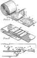
- FIG. 1 is a schematic drawing illustrating a batt of randomly oriented polymer fibers being cut to length in preparation for the winding step of the filter forming process.
- FIG. 2 is a schematic drawing of a series of batts forming the filter media being conveyed to the winding step of the filter forming process.
- FIG. 3 is a schematic drawing of the fibrous filter media made up of the series of batts having binder applied thereto as the filter media is conveyed to the cartridge winding station and being wound onto a core mounted on a mandrel in the winding station.
- FIG. 4 is a partial sectional view, taken substantially along lines 4-4 of FIG. 3, showing how a filter core can be mounted on the mandrel.
- FIG. 5 is a schematic drawing the cutting station of the process where grooves are cut into the outer surface of the cylindrical filter cartridge.
- FIG. 6 is a perspective view of a hollow, cylindrical filter cartridge of the present invention.
- FIG.7 is an enlarged detailed view of a portion of the filter cartridge of FIG. 6, taken substantially along lines 7-7 of FIG. 6, showing the flow of the liquid being filtered through the filter cartridge.
- FIG. 1 shows a bulk polymer fiber batt 20 which has been stored in a roll 22.
- the rolls are normally about two feet in diameter.
- the rolls 22 provide a convenient, relatively low volume method of storing large amounts of bulk fiber media.
- the bulk fiber batt 20 can be produced through commercially known fiberizing techniques where the thermoplastic polymer fibers are cooled, so that the fibers are no longer soft or tacky, prior to the collection of the fibers into the batt. Accordingly, the bulk polymer fiber batt 20 is substantially free of direct fiber-to-fiber bonding at their points of intersection within the batt and direct fiber-to-fiber bonding does not provide structural integrity to the batt 20.
- the layers of the bulk fiber batt in the roll 22 are separated by a lightweight kraft paper interleaf 24.
- the kraft paper interleaf 24 protects the fragile fibers and aids in fiber handling in subsequent stages of the process.
- the batt 22 is comprised of polymer fibers having average fiber diameters of from about 1 to about 25 microns.
- the polymer fibers must be dimensionally stable at the temperatures required to cure the binder which is subsequently applied to the batt 20 to bond the fibers together at their points of intersection.
- an acrylic latex binder is used as the polymeric emulsion binder which bonds the fibers together in the fibrous filter media 32 formed from the batt 20.
- Polycarbonate fibers have been used in batts 20 to produce a filter cartridge for FDA filtration applications e.g., the filtration of potable water, corn syrup, juices, etc. and poly butyl terphthalate ( hereinafter “polyester”) fibers have been used in batts to produce solvent resistant filter cartridges. Both of these fibers have the dimensional stability required at the curing temperatures of acrylic latex binders.
- low temperature fibers such as, acrylic and polyethylene fibers would tend to melt or shrink at the temperatures required to cure the acrylic latex binder. The melting or the shrinkage of the fibers would reduce or destroy the porosity of the filter cartridge. Accordingly, low temperature fibers, such as, acrylic or polyethylene fibers can not be used in the preferred filter cartridges 50 of the present invention.
- the batt 20 is not uniform in thickness across its width.
- the batt is thickest in the center and has tapered or feathered side edges 26.
- the batt 20 is unrolled from roll 22 and cut into discrete lengths along with the kraft paper interleaf which continues to provide support for the batt of unbonded fibers.
- the length of each individual batt 28 is normally about two inches longer than the length of the cylindrical filter cartridge to be produced.
- the length of each individual batt 28 is thirty-two inches when forming a thirty inch filter cartridge and forty-two inches when forming a forty inch filter cartridge.
- Rotary knives, chop saws or other conventional cutting means can be used to cut the batt 20 to the lengths desired for the individual batts 28.
- the individual batts 28 are placed on an endless belt conveyor 30 and the kraft paper interleaf 24 is removed from beneath each individual batt 28.
- the individual batts 28 are laid sideways across the endless conveyor belt 30 with the feathered edges 26 of the individual batts 28 in overlapping relationship.
- FIG. 2 shows four individual batts 28 placed on the conveyor belt 30 in overlapping relationship to form a blanket 32 of filter media, for the winding operation, that is substantially uniform in thickness and density.
- the number of individual batts 28 placed on the conveyor 30 for the formation of each filter cartridge depends on the thickness and the density of the filter cartridge to be produced.
- all of the individual batts 28 placed on the conveyor 30 are formed with thermoplastic polymer fibers having the same average fiber diameter.
- the lead individual batt 28 of the blanket 32 of filter media is formed of finer diameter fibers than the following individual batts 28 to give the filter cartridge a dual stage depth filtration effect.
- the filter forming blanket 32 comprising a plurality of the individual batts 28, is fed toward a winding station 34 by the conveyor belt 30 which is driven by a conventional variable speed motor.
- an acrylic binder diluted with water
- the binder spray station comprises a plurality of individual spray nozzles 38 aligned across the width of the conveyor belt 30.
- the diluted binder is applied across the entire width of the filter media blanket 32.
- the winding station 34 comprises a rotating, cylindrical, mandrel 40, and a compression roll assembly 42.
- the rotating mandrel 40 is preferably made of aluminum or stainless steel and, as shown in FIG. 4 the mandrel 40 is driven by a conventional variable speed motor 41.
- the compression roll assembly 42 comprises a rotating compression roll 44 mounted on a pair of air cylinders 46. In operation, the compression roll 44 is in contact with and driven by the surface of the rotating cylindrical filter cartridge being formed on the mandrel 40.
- a tubular, foraminous, filter cartridge core 48 made of polypropylene or some other acceptable material is locked in place on the mandrel 40 during the winding, foaming, curing, grooving and surfacing steps of the process.
- the filter cartridge core 48 has a pair of notches 49 at each end.
- the mandrel 40 is provided with spring loaded locating pins 60 and 62 at one end which are received in the notches 49 at one end of the core 48 and a removable collar 64 at the other end.
- the collar 64 has a pair of teeth or projections 66 and 68 that are received in the notches 49 at the opposite end of the core 48.
- the collar is secured to the mandrel 40 by a set screw 70.
- the filter media blanket 32 As the filter media blanket 32 is fed into the winding station 34, the upper surface of the blanket, with the recently applied tacky binder thereon, sticks to and is picked up by the filter cartridge core 48. Thus, the filter media blanket 32 is wrapped onto the filter cartridge core 48 which is rotated at a rate to have substantially the same surface speed as the filter media blanket being fed into the winding station 34.
- the outer surface of the filter media blanket 32 comes in contact with the compression roll 44 which compresses the filter media blanket between the compression roll 44 and the filter core 48.
- the surface of the compression roll 44 is coated with teflon or some other material to keep the filter media blanket 32 from sticking to the compression roll.
- the filter media blanket 32 is spirally wrapped about the filter core 48 on the mandrel 40 at a low rate of revolutions per minute (e.g. about 1 to about 50 rpm) until the blanket 32 is fully wrapped onto the core. While the filter media blanket 32 is being wrapped about the filter core 48, the blanket 32 continues to be compressed between the compression roll 44 and the filter core 48.
- the spacing between the compression roll 44 and the filter core 48 at the initiation of a winding cycle is less than an 1/8 of an inch to assure that the blanket 32, which is greater than 1/8 of an inch in thickness, is compressed between the compression roll and the filter core.
- the air cylinders 46 automatically increase the spacing between the compression roll 44 and the filter core 48 to maintain the filter media under compression while avoiding subjecting the filter media to excessive compression whereby the fragile fibers of the filter media would be broken or filter permeability would be significantly reduced.
- the surface speed of the filter media in contact with the compression roll 44 increases. Accordingly, the rate of rotation of the compression roll 44 and thereby the surface speed of the surface of the compression roll 44 is also increased to maintain the surface speed of the filter media blanket surface in contact with the compression roll and the surface speed of the compression roll at substantially the same speed. This keeps the filter media blanket from being subjected to shearing forces which could tear or otherwise damage the filter media blanket 32.
- the feed rate of the conveyor 30 is synchronized with the surface speed of the compression roll so that, as the diameter of the cylindrical filter cartridge 50 being formed increases and the filter media blanket 32 is wrapped faster, the conveyor feed rate automatically increases. This too keeps the filter media blanket 32 from being subjected to undesirable stresses which could tear or otherwise damage the filter media blanket.
- Conventional commercially available control systems are used to regulate the spacing between the filter core 48 and the compression roll 44 and the speeds of the mandrel 40, the compression roll 44 and the conveyor belt 30.
- the low speed (e.g., 1 to 50 revolutions per minute) wrapping operation is followed by a high speed spinning operation.
- the compression roll 44 maintains the filter media blanket 32 in compression between the compression roll and the filter core.
- the speed of rotation of the spinning operation is sufficient to cause the water diluted acrylic latex binder in the filter media blanket 32, under the compressive forces of the compression roll 44, to foam in-situ.
- a speed of rotation of the mandrel 40 as low as 300 rpm has been found to be sufficient to cause the water diluted acrylic latex binder to foam under the influence of the compressive forces of the compression roll 44.
- the binder does not foam very quickly and it is preferred to rotate the mandrel at about 800 rpm to effect a rapid foaming of the binder.
- the speed of rotation of the mandrel 40 is increased to 800 rpm, the speed of rotation of the compression roll 44 is also proportionally increased to maintain the surface speed of the outer surface of the cylindrical filter cartridge and the surface speed of the compression roll at substantially the same speed. This eliminates tearing or other damage to the outer surface of the cylindrical filter cartridge 50 which would be experienced if the surface speeds of the filter cartridge and the compression roll differed.
- the acrylic latex binder foams With the increase in speed of the cylindrical filter cartridge 50 to above 300 rpm and preferably about 800 rpm and with the compression of the filter media by the compression roll 44, the acrylic latex binder foams in place.
- the foam which has the consistency of shaving cream, fluidizes the cylindrical filter cartridge 50 and causes the fibers in the filter media 32 to be reoriented during the high speed spinning operation to form a smooth, uniform outer surface on the cylindrical filter cartridge 50.
- the generation of the foamed binder evenly distributes the binder throughout the cylindrical filter cartridge and saturates the cylindrical filter cartridge with binder without having to saturate the cylindrical filter cartridge with a liquid binder as in previous non-foaming filter forming operations.
- the foam is more than 50% air, the amount of water in the cylindrical filter cartridge 50 at this stage of the manufacturing operation is much less than in prior art manufacturing processes.
- the benefits of saturating the filter cartridge with foam as opposed to liquid are two fold. First, there is less water present which has to be evaporated during the curing of the binder. This reduces energy costs associated with the curing operation. Second, the foamed binder is far less subject to the effects of migration to the filter cartridge surface 52 than a liquid binder when the binder is cured and the cartridge is dried. As water is removed from the diluted acrylic latex binder during curing, the foam becomes unstable and breaks down leaving the binder evenly distributed on the fibers of the filter media 32.
- the foam breaks down it creates channels for the water vapor to escape from the inside of the cartridge structure. If a similar drying or curing technique was used on cartridges totally saturated with a liquid binder, the water evaporation would take place only on the surface of the filter cartridge and the water-borne binder would migrate to and become concentrated at the surface of the filter cartridge.
- the filter cartridge 50 and the mandrel 40 are removed from the winding station.
- the filter cartridge 50 is then batch dried and cured in a forced air oven for about 4 to 10 hours to fully cure the acrylic latex binder.
- the oven temperatures are appropriately ramped upward from ambient temperatures for each grade of filter cartridge to allow the foamed binder to become unstable, dry and cure with a minimal amount of binder migration.
- the time required to bring each grade of filter cartridge up to its maximum curing temperature and the time required for the curing of each grade of filter cartridge is determined by trial and error.
- the cartridges are cured at a maximum temperature of about 250 degrees Fahrenheit.
- the polyester fiber cartridges the cartridges are cured at a maximum temperature of about 270 degrees Fahrenheit.
- the dried and cured cylindrical filter cartridges 50 are then milled to an outside diameter of 2.6 - 2.7 inches using a surfacing machine 54, such as the lathe of FIG. 5. This improves the outer surface finish of the filter cartridge and provides the finished cylindrical filter cartridge 50 with the specific outside diameter tolerances required for the product.
- the lathe machine 54 is used to cut circular or annular grooves 56 in the outer surface 52 of the filter cartridge 50.
- the grooves 56 are approximately 1/8 of an inch in width and 1/4 of an inch in depth.
- the grooves 56 perform two functions. First, the grooves 56 provide additional surface area on the outside of the filter cartridge 50 so that more dirt can be filtered before excessive pressure build-up occurs across the filter cartridge. Second, as shown in FIG. 7, the grooves 56 allow the liquid being filtered to enter the body of the filter cartridge in a direction parallel to the axis of the filter cartridge.
- the permeability of the fibrous filter media in the direction parallel to the central longitudinal axis of the filter cartridge 50 is greater than in the radial direction. Since the fibrous filter media 32 is more open in this direction, the filter provides even greater dirt holding capacity and reduced pressure differentials across the filter cartridge 50.
- the filter cartridge is ready for finishing. This is accomplished by cutting the cartridge which may be thirty-two or forty-two inches or some other predetermined length into the lengths required by conventional filter housings. These lengths include lengths of 9.75, 10, 19.5, 20, 29.25, 30, 39 and 40 inches long.
- the cut filter cartridges are vacuumed to remove dust from the cutting operation, packaged in poly bags and labeled.
- the filter cartridges 50 made by the process of the present invention are unique in that they are capable of longer filtration service life at given filter efficiencies. This is believed to be the result of having a grooved exterior surface on the filter cartridge and because of the lofty bulk fiber of the filter media.
- the bulk is maintained in the filter media by the use of the binder to hold the fibers in place which retains the high permeability characteristics of the bulk fiber batts 28 that form the filter media blanket 32 in the finished filter cartridges.
- a polycarbonate fiber filter cartridge made in accordance with the present invention using an acrylic latex binder was tested in comparison with a polypropylene fiber filter cartridge of the prior art having unbonded, entangled or intertwined fibers.
- the test fluid was water; the contaminant was SAE coarse; the contaminant concentration was 1.0 g/gal.; the flow set was 3.0 gpm; and the pressure drop across the filter cartridge to end the test was 30 psi.
- the base turbidity of the filter cartridge of the present invention was 44.4 FTU and the base turbidity of the prior art filter cartridge was 52.9 FTU.
Landscapes
- Chemical & Material Sciences (AREA)
- Chemical Kinetics & Catalysis (AREA)
- Filtering Materials (AREA)
- Separation Using Semi-Permeable Membranes (AREA)
- Sampling And Sample Adjustment (AREA)
- Water Treatment By Sorption (AREA)
Priority Applications (7)
| Application Number | Priority Date | Filing Date | Title |
|---|---|---|---|
| US08/138,322 US5425907A (en) | 1993-10-18 | 1993-10-18 | Method of making a cylindrical filter cartridge |
| ES94116829T ES2096398T3 (es) | 1993-10-18 | 1994-10-25 | Metodo para la fabricacion de un cartucho de filtro cilindrico. |
| AT94116829T ATE148362T1 (de) | 1993-10-18 | 1994-10-25 | Methode zur herstellung einer zylindrischen filterkartusche |
| DE69401664T DE69401664T2 (de) | 1993-10-18 | 1994-10-25 | Methode zur Herstellung einer zylindrischen Filterkartusche |
| EP94116829A EP0715872B1 (fr) | 1993-10-18 | 1994-10-25 | Méthode de production d'une cartouche filtrante cylindrique |
| DK94116829.6T DK0715872T3 (da) | 1993-10-18 | 1994-10-25 | Fremgangsmåde til fremstilling af en cylindrisk fibrøs filterindsats |
| GR970400811T GR3023149T3 (en) | 1993-10-18 | 1997-04-15 | Cylindrical filter cartridge and method of making the same |
Applications Claiming Priority (2)
| Application Number | Priority Date | Filing Date | Title |
|---|---|---|---|
| US08/138,322 US5425907A (en) | 1993-10-18 | 1993-10-18 | Method of making a cylindrical filter cartridge |
| EP94116829A EP0715872B1 (fr) | 1993-10-18 | 1994-10-25 | Méthode de production d'une cartouche filtrante cylindrique |
Publications (2)
| Publication Number | Publication Date |
|---|---|
| EP0715872A1 true EP0715872A1 (fr) | 1996-06-12 |
| EP0715872B1 EP0715872B1 (fr) | 1997-01-29 |
Family
ID=26135888
Family Applications (1)
| Application Number | Title | Priority Date | Filing Date |
|---|---|---|---|
| EP94116829A Expired - Lifetime EP0715872B1 (fr) | 1993-10-18 | 1994-10-25 | Méthode de production d'une cartouche filtrante cylindrique |
Country Status (7)
| Country | Link |
|---|---|
| US (1) | US5425907A (fr) |
| EP (1) | EP0715872B1 (fr) |
| AT (1) | ATE148362T1 (fr) |
| DE (1) | DE69401664T2 (fr) |
| DK (1) | DK0715872T3 (fr) |
| ES (1) | ES2096398T3 (fr) |
| GR (1) | GR3023149T3 (fr) |
Families Citing this family (6)
| Publication number | Priority date | Publication date | Assignee | Title |
|---|---|---|---|---|
| US7037394B2 (en) * | 1994-01-07 | 2006-05-02 | Scan-Web I/S | Method and apparatus for manufacturing a dryformed fibrous web |
| KR100611848B1 (ko) * | 2000-02-24 | 2006-08-11 | 주식회사 코오롱 | 수직배수 드레인보드 필터재용 폴리에스테르 스펀본드부직포 |
| WO2002055774A2 (fr) * | 2000-11-14 | 2002-07-18 | Weyerhaeuser Co | Produit cellulosique reticule forme par un procede d'extrusion |
| BRPI0511006B1 (pt) * | 2004-06-17 | 2016-09-06 | Microban Products | sistema de filtração de ar de unidade de resfriamento e compartimento refrigerado por tal sistema. |
| US9283734B2 (en) | 2010-05-28 | 2016-03-15 | Gunite Corporation | Manufacturing apparatus and method of forming a preform |
| DE102011009325B4 (de) | 2011-01-18 | 2023-12-21 | Hydac Filtertechnik Gmbh | Verfahren und Formvorrichtung zum Herstellen eines Filterelements |
Citations (4)
| Publication number | Priority date | Publication date | Assignee | Title |
|---|---|---|---|---|
| BE629997A (fr) * | 1967-01-11 | 1900-01-01 | ||
| US3450632A (en) * | 1967-05-03 | 1969-06-17 | Chevron Res | Method for simultaneously coalescing,filtering and removing oil traces from liquids and media for accomplishing the same |
| DE2440998A1 (de) * | 1973-08-31 | 1975-03-13 | Pall Corp | Verfahren zur fortlaufenden herstellung nicht gewobener bahnen aus thermoplastischen fasern, und daraus hergestellte gegenstaende |
| US4594202A (en) * | 1984-01-06 | 1986-06-10 | Pall Corporation | Method of making cylindrical fibrous filter structures |
Family Cites Families (12)
| Publication number | Priority date | Publication date | Assignee | Title |
|---|---|---|---|---|
| US3768118A (en) * | 1971-01-21 | 1973-10-30 | Johnson & Johnson | Web forming process |
| US3740797A (en) * | 1971-01-21 | 1973-06-26 | Johnson & Johnson | Method of forming webs and apparatus therefor |
| US4018646A (en) * | 1973-05-09 | 1977-04-19 | Johnson & Johnson | Nonwoven fabric |
| JPS5434475A (en) * | 1977-08-18 | 1979-03-13 | Chisso Corp | Production of cylindrical fiber molded article containing granular solid |
| US4726901A (en) * | 1984-01-06 | 1988-02-23 | Pall Corporation | Cylindrical fibrous structures with graded pore size |
| US4619948A (en) * | 1985-01-07 | 1986-10-28 | Twin Rivers Engineering | Composite active filter material |
| US4661132A (en) * | 1985-08-15 | 1987-04-28 | Allied Corporation | Themally formed gradient density filter |
| US4895685A (en) * | 1986-01-23 | 1990-01-23 | General Director Of The Agency Of Industrial Science And Technology | Crosslinked composite membrane and process for producing the same |
| US4812283A (en) * | 1986-05-02 | 1989-03-14 | Allied-Signal Inc. | Method of manufacture of formed article |
| US4869855A (en) * | 1986-05-02 | 1989-09-26 | Allied Signal Inc. | Method of manufacturing molded articles |
| US4813948A (en) * | 1987-09-01 | 1989-03-21 | Minnesota Mining And Manufacturing Company | Microwebs and nonwoven materials containing microwebs |
| US4894157A (en) * | 1987-10-05 | 1990-01-16 | Micron Separations, Inc. | Process for producing supported celluosic membranes and products |
-
1993
- 1993-10-18 US US08/138,322 patent/US5425907A/en not_active Expired - Fee Related
-
1994
- 1994-10-25 ES ES94116829T patent/ES2096398T3/es not_active Expired - Lifetime
- 1994-10-25 DK DK94116829.6T patent/DK0715872T3/da active
- 1994-10-25 EP EP94116829A patent/EP0715872B1/fr not_active Expired - Lifetime
- 1994-10-25 DE DE69401664T patent/DE69401664T2/de not_active Expired - Fee Related
- 1994-10-25 AT AT94116829T patent/ATE148362T1/de not_active IP Right Cessation
-
1997
- 1997-04-15 GR GR970400811T patent/GR3023149T3/el unknown
Patent Citations (4)
| Publication number | Priority date | Publication date | Assignee | Title |
|---|---|---|---|---|
| BE629997A (fr) * | 1967-01-11 | 1900-01-01 | ||
| US3450632A (en) * | 1967-05-03 | 1969-06-17 | Chevron Res | Method for simultaneously coalescing,filtering and removing oil traces from liquids and media for accomplishing the same |
| DE2440998A1 (de) * | 1973-08-31 | 1975-03-13 | Pall Corp | Verfahren zur fortlaufenden herstellung nicht gewobener bahnen aus thermoplastischen fasern, und daraus hergestellte gegenstaende |
| US4594202A (en) * | 1984-01-06 | 1986-06-10 | Pall Corporation | Method of making cylindrical fibrous filter structures |
Also Published As
| Publication number | Publication date |
|---|---|
| DE69401664T2 (de) | 1997-05-28 |
| ATE148362T1 (de) | 1997-02-15 |
| DK0715872T3 (da) | 1997-08-18 |
| EP0715872B1 (fr) | 1997-01-29 |
| US5425907A (en) | 1995-06-20 |
| GR3023149T3 (en) | 1997-07-30 |
| ES2096398T3 (es) | 1997-03-01 |
| DE69401664D1 (de) | 1997-03-13 |
Similar Documents
| Publication | Publication Date | Title |
|---|---|---|
| US4961974A (en) | Laminated filters | |
| US3933557A (en) | Continuous production of nonwoven webs from thermoplastic fibers and products | |
| US4116738A (en) | Continuous production of tubular modular filter elements using nonwoven webs from thermoplastic fibers and products | |
| US4661132A (en) | Themally formed gradient density filter | |
| EP0352888B1 (fr) | Tissu filtrant produit par application par voie humide | |
| JP4731642B2 (ja) | 多孔構造体及びその製造方法 | |
| US4749423A (en) | Method of making a bonded nonwoven web | |
| US6938781B2 (en) | Three-dimensional non-woven filter | |
| US3592767A (en) | Laminated filter sheets and filter elements and process for making the same | |
| US7033497B1 (en) | Filter cartridge | |
| AU2002244174B2 (en) | Wet-felted and thermally bonded porous structures | |
| EP0715872B1 (fr) | Méthode de production d'une cartouche filtrante cylindrique | |
| US6555489B1 (en) | Filter composite embodying glass fiber and synthetic resin fiber | |
| JPS6046065B2 (ja) | 複合強化セラミツクス材料構造体の製造方法 | |
| US5028465A (en) | Hydroentangled composite filter element | |
| US20020148776A1 (en) | Water filtration media and methods of making same | |
| JPH08141323A (ja) | 円筒状フィルタカートリッジ及びその製造方法 | |
| JPH0730783B2 (ja) | 繊維ロールの製作方法 | |
| JPH01115423A (ja) | セルロース・スパンボンド不織布を素材とする濾過体の製造方法 | |
| JP3390498B2 (ja) | 布はく、その巻き取り方法およびその巻き取り装置 | |
| KR20030082436A (ko) | 절단유리섬유 매트 및 그 제조방법 | |
| JPWO2000057989A1 (ja) | フィルターカートリッジ | |
| JPH09150023A (ja) | 濾 材 | |
| JP3712464B2 (ja) | カートリッジフィルター及びその製造方法 | |
| JPH0237205B2 (ja) | Kaafuirutaaerementooyobisonoseizohoho |
Legal Events
| Date | Code | Title | Description |
|---|---|---|---|
| PUAI | Public reference made under article 153(3) epc to a published international application that has entered the european phase |
Free format text: ORIGINAL CODE: 0009012 |
|
| GRAG | Despatch of communication of intention to grant |
Free format text: ORIGINAL CODE: EPIDOS AGRA |
|
| 17P | Request for examination filed |
Effective date: 19950609 |
|
| AK | Designated contracting states |
Kind code of ref document: A1 Designated state(s): AT BE CH DE DK ES FR GB GR IE IT LI LU MC NL PT SE |
|
| GRAH | Despatch of communication of intention to grant a patent |
Free format text: ORIGINAL CODE: EPIDOS IGRA |
|
| GRAH | Despatch of communication of intention to grant a patent |
Free format text: ORIGINAL CODE: EPIDOS IGRA |
|
| GRAA | (expected) grant |
Free format text: ORIGINAL CODE: 0009210 |
|
| AK | Designated contracting states |
Kind code of ref document: B1 Designated state(s): AT BE CH DE DK ES FR GB GR IE IT LI LU MC NL PT SE |
|
| REF | Corresponds to: |
Ref document number: 148362 Country of ref document: AT Date of ref document: 19970215 Kind code of ref document: T |
|
| REG | Reference to a national code |
Ref country code: CH Ref legal event code: NV Representative=s name: E. BLUM & CO. PATENTANWAELTE Ref country code: CH Ref legal event code: EP |
|
| ITF | It: translation for a ep patent filed | ||
| REG | Reference to a national code |
Ref country code: ES Ref legal event code: FG2A Ref document number: 2096398 Country of ref document: ES Kind code of ref document: T3 |
|
| REG | Reference to a national code |
Ref country code: IE Ref legal event code: FG4D Free format text: 71906 |
|
| REF | Corresponds to: |
Ref document number: 69401664 Country of ref document: DE Date of ref document: 19970313 |
|
| ET | Fr: translation filed | ||
| REG | Reference to a national code |
Ref country code: PT Ref legal event code: SC4A Free format text: AVAILABILITY OF NATIONAL TRANSLATION Effective date: 19970129 |
|
| REG | Reference to a national code |
Ref country code: GR Ref legal event code: FG4A Free format text: 3023149 |
|
| REG | Reference to a national code |
Ref country code: DK Ref legal event code: T3 |
|
| PLBE | No opposition filed within time limit |
Free format text: ORIGINAL CODE: 0009261 |
|
| STAA | Information on the status of an ep patent application or granted ep patent |
Free format text: STATUS: NO OPPOSITION FILED WITHIN TIME LIMIT |
|
| 26N | No opposition filed | ||
| PGFP | Annual fee paid to national office [announced via postgrant information from national office to epo] |
Ref country code: MC Payment date: 19981008 Year of fee payment: 5 |
|
| PGFP | Annual fee paid to national office [announced via postgrant information from national office to epo] |
Ref country code: LU Payment date: 19981013 Year of fee payment: 5 |
|
| PGFP | Annual fee paid to national office [announced via postgrant information from national office to epo] |
Ref country code: CH Payment date: 19981019 Year of fee payment: 5 |
|
| PGFP | Annual fee paid to national office [announced via postgrant information from national office to epo] |
Ref country code: IE Payment date: 19990131 Year of fee payment: 6 |
|
| PG25 | Lapsed in a contracting state [announced via postgrant information from national office to epo] |
Ref country code: LU Free format text: LAPSE BECAUSE OF NON-PAYMENT OF DUE FEES Effective date: 19991025 |
|
| PG25 | Lapsed in a contracting state [announced via postgrant information from national office to epo] |
Ref country code: LI Free format text: LAPSE BECAUSE OF NON-PAYMENT OF DUE FEES Effective date: 19991031 Ref country code: CH Free format text: LAPSE BECAUSE OF NON-PAYMENT OF DUE FEES Effective date: 19991031 |
|
| PGFP | Annual fee paid to national office [announced via postgrant information from national office to epo] |
Ref country code: SE Payment date: 19991220 Year of fee payment: 6 Ref country code: AT Payment date: 19991220 Year of fee payment: 6 |
|
| PGFP | Annual fee paid to national office [announced via postgrant information from national office to epo] |
Ref country code: DK Payment date: 19991221 Year of fee payment: 6 |
|
| PGFP | Annual fee paid to national office [announced via postgrant information from national office to epo] |
Ref country code: PT Payment date: 19991223 Year of fee payment: 6 Ref country code: NL Payment date: 19991223 Year of fee payment: 6 |
|
| PGFP | Annual fee paid to national office [announced via postgrant information from national office to epo] |
Ref country code: GR Payment date: 19991229 Year of fee payment: 6 |
|
| PGFP | Annual fee paid to national office [announced via postgrant information from national office to epo] |
Ref country code: ES Payment date: 19991231 Year of fee payment: 6 |
|
| PGFP | Annual fee paid to national office [announced via postgrant information from national office to epo] |
Ref country code: BE Payment date: 20000107 Year of fee payment: 6 |
|
| PG25 | Lapsed in a contracting state [announced via postgrant information from national office to epo] |
Ref country code: MC Free format text: LAPSE BECAUSE OF NON-PAYMENT OF DUE FEES Effective date: 20000430 |
|
| REG | Reference to a national code |
Ref country code: CH Ref legal event code: PL |
|
| PG25 | Lapsed in a contracting state [announced via postgrant information from national office to epo] |
Ref country code: IE Free format text: LAPSE BECAUSE OF NON-PAYMENT OF DUE FEES Effective date: 20001025 Ref country code: DK Free format text: LAPSE BECAUSE OF NON-PAYMENT OF DUE FEES Effective date: 20001025 Ref country code: AT Free format text: LAPSE BECAUSE OF NON-PAYMENT OF DUE FEES Effective date: 20001025 |
|
| PG25 | Lapsed in a contracting state [announced via postgrant information from national office to epo] |
Ref country code: ES Free format text: LAPSE BECAUSE OF NON-PAYMENT OF DUE FEES Effective date: 20001026 |
|
| PG25 | Lapsed in a contracting state [announced via postgrant information from national office to epo] |
Ref country code: SE Free format text: THE PATENT HAS BEEN ANNULLED BY A DECISION OF A NATIONAL AUTHORITY Effective date: 20001030 |
|
| PG25 | Lapsed in a contracting state [announced via postgrant information from national office to epo] |
Ref country code: GR Free format text: LAPSE BECAUSE OF NON-PAYMENT OF DUE FEES Effective date: 20001031 Ref country code: BE Free format text: LAPSE BECAUSE OF NON-PAYMENT OF DUE FEES Effective date: 20001031 |
|
| BERE | Be: lapsed |
Owner name: SCHULLER INTERNATIONAL INC. Effective date: 20001031 |
|
| PG25 | Lapsed in a contracting state [announced via postgrant information from national office to epo] |
Ref country code: PT Free format text: LAPSE BECAUSE OF NON-PAYMENT OF DUE FEES Effective date: 20010430 |
|
| PG25 | Lapsed in a contracting state [announced via postgrant information from national office to epo] |
Ref country code: NL Free format text: LAPSE BECAUSE OF NON-PAYMENT OF DUE FEES Effective date: 20010501 |
|
| REG | Reference to a national code |
Ref country code: DK Ref legal event code: EBP |
|
| EUG | Se: european patent has lapsed |
Ref document number: 94116829.6 |
|
| NLV4 | Nl: lapsed or anulled due to non-payment of the annual fee |
Effective date: 20010501 |
|
| REG | Reference to a national code |
Ref country code: IE Ref legal event code: MM4A |
|
| REG | Reference to a national code |
Ref country code: GB Ref legal event code: IF02 |
|
| PGFP | Annual fee paid to national office [announced via postgrant information from national office to epo] |
Ref country code: GB Payment date: 20021106 Year of fee payment: 9 |
|
| PGFP | Annual fee paid to national office [announced via postgrant information from national office to epo] |
Ref country code: FR Payment date: 20021119 Year of fee payment: 9 |
|
| PGFP | Annual fee paid to national office [announced via postgrant information from national office to epo] |
Ref country code: DE Payment date: 20021202 Year of fee payment: 9 |
|
| PG25 | Lapsed in a contracting state [announced via postgrant information from national office to epo] |
Ref country code: GB Free format text: LAPSE BECAUSE OF NON-PAYMENT OF DUE FEES Effective date: 20031025 |
|
| PG25 | Lapsed in a contracting state [announced via postgrant information from national office to epo] |
Ref country code: DE Free format text: LAPSE BECAUSE OF NON-PAYMENT OF DUE FEES Effective date: 20040501 |
|
| REG | Reference to a national code |
Ref country code: ES Ref legal event code: FD2A Effective date: 20011113 |
|
| GBPC | Gb: european patent ceased through non-payment of renewal fee |
Effective date: 20031025 |
|
| PG25 | Lapsed in a contracting state [announced via postgrant information from national office to epo] |
Ref country code: FR Free format text: LAPSE BECAUSE OF NON-PAYMENT OF DUE FEES Effective date: 20040630 |
|
| REG | Reference to a national code |
Ref country code: FR Ref legal event code: ST |
|
| PG25 | Lapsed in a contracting state [announced via postgrant information from national office to epo] |
Ref country code: IT Free format text: LAPSE BECAUSE OF NON-PAYMENT OF DUE FEES;WARNING: LAPSES OF ITALIAN PATENTS WITH EFFECTIVE DATE BEFORE 2007 MAY HAVE OCCURRED AT ANY TIME BEFORE 2007. THE CORRECT EFFECTIVE DATE MAY BE DIFFERENT FROM THE ONE RECORDED. Effective date: 20051025 |