EP0715939A2 - Plattenspritzgiessvorrichtung mit Öffnungsführungsmitteln mit Klauenkupplung - Google Patents
Plattenspritzgiessvorrichtung mit Öffnungsführungsmitteln mit Klauenkupplung Download PDFInfo
- Publication number
- EP0715939A2 EP0715939A2 EP95110037A EP95110037A EP0715939A2 EP 0715939 A2 EP0715939 A2 EP 0715939A2 EP 95110037 A EP95110037 A EP 95110037A EP 95110037 A EP95110037 A EP 95110037A EP 0715939 A2 EP0715939 A2 EP 0715939A2
- Authority
- EP
- European Patent Office
- Prior art keywords
- guide
- disk
- injection molding
- molding device
- grooves
- Prior art date
- Legal status (The legal status is an assumption and is not a legal conclusion. Google has not performed a legal analysis and makes no representation as to the accuracy of the status listed.)
- Granted
Links
- 238000001746 injection moulding Methods 0.000 title claims abstract description 32
- 239000000463 material Substances 0.000 claims abstract description 14
- 230000008878 coupling Effects 0.000 claims abstract description 4
- 238000010168 coupling process Methods 0.000 claims abstract description 4
- 238000005859 coupling reaction Methods 0.000 claims abstract description 4
- 238000005452 bending Methods 0.000 claims description 3
- 238000006073 displacement reaction Methods 0.000 abstract description 10
- 238000000465 moulding Methods 0.000 description 10
- 239000011347 resin Substances 0.000 description 8
- 229920005989 resin Polymers 0.000 description 8
- 230000003287 optical effect Effects 0.000 description 7
- 230000007246 mechanism Effects 0.000 description 4
- 238000002347 injection Methods 0.000 description 3
- 239000007924 injection Substances 0.000 description 3
- 239000000314 lubricant Substances 0.000 description 3
- PXHVJJICTQNCMI-UHFFFAOYSA-N Nickel Chemical compound [Ni] PXHVJJICTQNCMI-UHFFFAOYSA-N 0.000 description 2
- 239000011248 coating agent Substances 0.000 description 2
- 238000000576 coating method Methods 0.000 description 2
- 238000000034 method Methods 0.000 description 2
- CWQXQMHSOZUFJS-UHFFFAOYSA-N molybdenum disulfide Chemical compound S=[Mo]=S CWQXQMHSOZUFJS-UHFFFAOYSA-N 0.000 description 2
- 229910052982 molybdenum disulfide Inorganic materials 0.000 description 2
- 230000008569 process Effects 0.000 description 2
- 230000000712 assembly Effects 0.000 description 1
- 238000000429 assembly Methods 0.000 description 1
- 230000015556 catabolic process Effects 0.000 description 1
- 230000008859 change Effects 0.000 description 1
- 238000006731 degradation reaction Methods 0.000 description 1
- 239000012535 impurity Substances 0.000 description 1
- 238000004519 manufacturing process Methods 0.000 description 1
- 229910001105 martensitic stainless steel Inorganic materials 0.000 description 1
- 238000012986 modification Methods 0.000 description 1
- 230000004048 modification Effects 0.000 description 1
- 229910052759 nickel Inorganic materials 0.000 description 1
- 238000004381 surface treatment Methods 0.000 description 1
Images



Classifications
-
- B—PERFORMING OPERATIONS; TRANSPORTING
- B29—WORKING OF PLASTICS; WORKING OF SUBSTANCES IN A PLASTIC STATE IN GENERAL
- B29C—SHAPING OR JOINING OF PLASTICS; SHAPING OF MATERIAL IN A PLASTIC STATE, NOT OTHERWISE PROVIDED FOR; AFTER-TREATMENT OF THE SHAPED PRODUCTS, e.g. REPAIRING
- B29C45/00—Injection moulding, i.e. forcing the required volume of moulding material through a nozzle into a closed mould; Apparatus therefor
- B29C45/17—Component parts, details or accessories; Auxiliary operations
- B29C45/26—Moulds
- B29C45/263—Moulds with mould wall parts provided with fine grooves or impressions, e.g. for record discs
Definitions
- the present invention relates to a disk injection molding device having a dog-clutch opening guide means for preventing the shaft center displacement caused in die opening between fixed and movable disk cavity dies of an injection molding die for optical disks and the like, and more particularly, to a disk injection molding device having a dog-clutch opening guide means capable of preventing bits transferred onto the surface of a molded optical disk from being damaged by the shaft center displacement between fixed and movable disk cavity dies which is caused in die opening after completion of injection molding.
- a well-known type of disk injection molding device for molding magneto-optical disks by injection is provided with fixed and movable die bases, cylindrical disk cavity dies located in the center of the respective die bases, and a pair of cylindrical guide rings functioning as aligning guide means for the disk cavity dies, which respectively are concentrically located on the outer periphery of the respective disk cavity dies and provided with male and female taper-engaging surfaces in a shaft hole connecting portion at the leading end thereof to be engaged with each other.
- Fig. 6 is a front sectional view showing a conventional disk injection molding device in a die clamping state
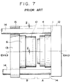
- Fig. 7 shows the molding device in a die opening state to explain problems thereof.
- a and B respectively denote a fixed die assembly and a movable die assembly.
- a fixed disk cavity die 2 is fixed to a fixed die base 1 in the fixed die assembly A, and provided with an injection nozzle 3 for molten resin material in the center thereof.
- a fixed guide ring 4 having a cylindrical shape is fixed integrally to the periphery of the fixed die base 1, and provided with a male tapered surface 5 with a 3 to 5 degree slope at the left end thereof. Resin is supplied from a nozzle 28 of an injection molding machine into the center hole of the fixed die base 1 in injection molding.
- a movable disk cavity die 7 is fixed to a movable die base 6 in the movable die assembly B, thereby forming a cavity 8 between the fixed disk cavity die 2 and the movable disk cavity die 7 to be charged with molten resin material.
- a stamper plate 9 made of pure nickel has fine signal bits engraved on the surface (the right side in the figure) thereof, and is fixed to the surface of the movable disk cavity die 7 by an unillustrated attachment member.
- a cylindrical movable guide ring 10 is integrally fixed onto the outer periphery of the movable die base 6 or the movable disk cavity die 7, and provided with a female tapered surface 11, which is to be precisely engaged with the male tapered surface 5 in the fixed die assembly A, at the right end thereof.
- the above die assemblies A and B are respectively mounted to fixed and movable platens 12 and 13 of the injection molding machine.
- molten resin material is charged from the injection nozzle 28 into the cavity 8 formed by the cavity dies 2 and 7 under high pressure, by which the fine signal bits of the stamper plate 9 are transferred onto the surface of a resin molded piece.
- die opening is performed by moving the movable platen 13 backward, and then, the whole resin molded piece is taken out of the cavity dies 2 and 7.
- the movable platen 13 is held by four guide rods 14 and driven by pressurized power of an unillustrated toggle mechanism or hydraulic piston.
- clearances formed between bearings 15 of the movable platen 13 and the guide rods 14 and a downward deflection amount ⁇ of the guide rods 14, resulting from the weight of the movable platen 13 and the movable die assembly B gradually deflect and shift, by the deflection amount ⁇ , the shaft center of the movable die assembly B, which is aligned with the shaft center of the fixed die assembly A by the above-mentioned taper guide mechanism in the die clamping state, from the shaft center of the fixed die assembly A during the die opening process.
- the deflection amount ⁇ of an injection molding machine having a die clamping force of more than 75 tons normally measures 50 ⁇ m to 70 ⁇ m.
- the shaft center displacement between the fixed and movable dies A and B requires to be kept zero until the die stroke reaches at least 200 ⁇ m. If not, for example, fine signal bits transferred on the resin molded piece are deformed or double-transferred. If the taper angle of each guide ring is, for example, five degrees, the deflection amount ⁇ may reach 17.5 ⁇ m when the die stroke is 200 ⁇ m.
- An object of the present invention is to provide a disk injection molding device having a dog-clutch opening guide means which can prevent the displacement between fixed and movable disk cavity dies in die opening.
- a disk injection molding device with a dog-clutch die opening guide means for moving dies horizontally, having fixed and movable die bases, cylindrical disk cavity dies mounted in the center of the respective bases, and a pair of cylindrical guide rings concentrically located, as aligning guide means for the disk cavity dies, on the outer periphery of the disk cavity dies and having male and female taper engaging surfaces in a shaft hole connecting portion at the leading ends thereof, which disk injection molding device comprising a plurality of grooves formed in the axial direction to pierce between the inner periphery and the outer periphery from the leading end of the taper-engaging surface on the outside cylindrical surface of one of the guide rings, and a plurality of guide blocks made of hard material to protrude from the leading end of the other guide ring and be slidably and precisely engaged with the plurality of parallel grooves of the one guide ring, wherein the cavity dies are concentrically held by a dog-clutch slidable coup
- More than three grooves may be formed on the guide ring outside cylindrical surface at regular intervals.
- the guide blocks may be structured by fixing guide blocks made of wear-resistant material, such as cemented carbide, into grooves on the other guide ring corresponding to the plurality of grooves of the one guide ring to protrude from the leading end surface of the other guide ring.
- wear-resistant material such as cemented carbide
- a plate member made of wear-resistant material, such as cemented carbide, may be fixed onto both surfaces of each groove to be engaged with the surfaces of each block or all over the groove.
- a material used for the guide grooves and the guide blocks may be a cemented carbide having a rockwell hardness HR of A83 to 89 and a transverse bending force of 200kgf/mm2.
- Fig. 1 is a side view of a fixed guide ring used in a disk injection molding device having a dog-clutch opening guide means according to an embodiment of the present invention
- Fig. 2 is a partially cutaway front view of the fixed guide ring.
- a male tapered surface 17 with a 5-degree slope is formed at the left end of a fixed guide ring 16.
- the slope is exaggerated for easy illustration and understanding.
- An entrance 18a of each groove 18 is a little wider than the above-mentioned width W1.
- Fig. 3 is a partially cutaway front view of a movable guide ring of the molding device according to the embodiment of the present invention
- Fig. 4 is a side view of the movable guide ring.
- a cylindrical movable guide ring 19 has a female tapered surface 20, which has the same taper angle as the male tapered surface of the fixed guide ring 16, on the periphery at the right end thereof, and a pair of precisely worked parallel grooves 21 having the width W1 are formed on the right and left sides of the outside cylindrical surface thereof corresponding to the grooves 18 of the fixed guide ring 16.
- guide blocks 22 made of cemented carbide and having a width W2 and a height, that is, a projection length (S1-S2) from the surface of the movable guide ring 19 are respectively fixed by check bolts.
- the fixed and movable guide rings 16 and 19 are respectively fixed to the same fixed and movable die bases as shown in Figs. 6 and 7 by unillustrated check bolts.
- the guide blocks 22 are made of a cemented carbide having a rockwell hardness HR of A83 to 89 and a transverse bending force of 200kgf/mm2.
- the material of the fixed and movable guide rings 16 and 19 is a martensitic stainless steel, such as SUS420 and SUS440, which is treated with heat and hardened to achieve HR C52 to 60. Wear-resistant surface treatment, for example, molybdenum disulfide coating, is applied to the fixed guide ring 16.
- the wear resistance can be further enhanced by fixing rectangular plates made of wear-resistant material, such as cemented carbide, by check bolts onto the upper and lower surfaces of the precisely worked parallel grooves 18 of the fixed guide ring 16 which are to be contacted with the upper and lower surfaces of the cemented carbide guide blocks 22, or all over the parallel grooves 18.
- wear-resistant material such as cemented carbide
- Die production is required to be done so precisely that the engagement clearance between the width W1 of the precisely worked parallel grooves 18 of the fixed guide ring 16 and the width W2 of the guide blocks 22 of the movable guide ring 19 is less than 3 ⁇ m at room temperature.
- An engagement length S1 of each guide block 22 and each precise parallel groove 18 of the fixed guide ring 16 is set at least 5mm longer than a length S2 of the tapered portion, by which the guide block 22 engages with the precisely worked parallel groove 18, 5mm ahead of the tapered guide surfaces.
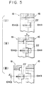
- Fig. 5 is a motion view of the disk injection molding device having a dog-clutch opening guide means according to the present invention.
- Fig. 5(I) shows a coupling state between the fixed guide ring 16 and the movable guide ring 19 in a die clamping position.
- the tapered guide surfaces 17 and 20, and the guide block 22 and the precise parallel groove 18 of the fixed guide ring 16 are simultaneously engaged with each other. Therefore, a center line ⁇ aa ⁇ of the fixed die assembly A and a center line ⁇ bb ⁇ of the movable die assembly B coincide with each other.
- Fig. 5(II) shows a state in which the tapered guide surfaces 17 and 20 are held by the guide blocks 22, the center line ⁇ aa ⁇ of the fixed die assembly A and the center line ⁇ bb ⁇ of the movable die assembly B coincide with each other, and the die stroke is extremely short, S1.
- Fig. 5(III) shows a state at a moment when the die stroke exceeds S2 and the guide block 22 of the movable die assembly B is detached from the precise parallel grooves 18 of the fixed guide ring 16.
- the center line ⁇ bb ⁇ of the movable die assembly B rapidly falls and shifts from the center line ⁇ aa ⁇ of the fixed die assembly A by the above-mentioned deflection amount ⁇ .
- the center line ⁇ aa ⁇ of the fixed die assembly A and the center line ⁇ bb ⁇ of the movable die assembly B can coincide with each other within a predetermined range at the beginning of die opening, thereby keeping the amount of shaft center displacement zero.
- a pair of guide blocks are respectively located on the right and left sides of the movable guide ring in the embodiment, more than three pairs of guide blocks and precise parallel grooves may be located radially relative to the center of the fixed and movable guide rings, which can limit the horizontal and vertical shaft center displacement between the fixed die assembly A and the movable die assembly B.
- a disk injection molding device having a die opening guide means according to the present invention is provided with a guide mechanism capable of moving a fixed die and a movable die in parallel to prevent the vertical shaft center displacement between the fixed die and the movable die caused in die opening after injection molding. Therefore, it is also possible to prevent the degradation resulting from the displacement and double transfer of fine signal bits transferred on a molded optical disk.
- both or one of the guide block and the guide groove are made of cemented carbide, sufficient durability and stability for wear resistance can be obtained even in a condition where lubricant cannot be used.
- a disk injection molding device having a die opening guide means can be provided by improving only guide rings of a conventional molding device without special change of structure.
Landscapes
- Engineering & Computer Science (AREA)
- Manufacturing & Machinery (AREA)
- Mechanical Engineering (AREA)
- Moulds For Moulding Plastics Or The Like (AREA)
- Manufacturing Optical Record Carriers (AREA)
Applications Claiming Priority (2)
| Application Number | Priority Date | Filing Date | Title |
|---|---|---|---|
| JP33177694A JP3258188B2 (ja) | 1994-12-09 | 1994-12-09 | 鰓クラッチ状型開き案内手段をもつディスク射出成形金型装置 |
| JP331776/94 | 1994-12-09 |
Publications (3)
| Publication Number | Publication Date |
|---|---|
| EP0715939A2 true EP0715939A2 (de) | 1996-06-12 |
| EP0715939A3 EP0715939A3 (de) | 1996-12-27 |
| EP0715939B1 EP0715939B1 (de) | 1999-04-21 |
Family
ID=18247509
Family Applications (1)
| Application Number | Title | Priority Date | Filing Date |
|---|---|---|---|
| EP19950110037 Expired - Lifetime EP0715939B1 (de) | 1994-12-09 | 1995-06-28 | Plattenspritzgiessvorrichtung mit Öffnungsführungsmitteln mit Klauenkupplung |
Country Status (3)
| Country | Link |
|---|---|
| EP (1) | EP0715939B1 (de) |
| JP (1) | JP3258188B2 (de) |
| DE (1) | DE69509197T2 (de) |
Cited By (5)
| Publication number | Priority date | Publication date | Assignee | Title |
|---|---|---|---|---|
| EP0774336A1 (de) * | 1995-11-17 | 1997-05-21 | SEIKOH GIKEN Co., Ltd. | Vorrichtung zum Ausrichten und Führen eines festen und eines beweglichen Plattenformteiles in Spritzgiessformen für Platten |
| EP0899075A1 (de) * | 1997-08-29 | 1999-03-03 | Seikoh Giken Co., Ltd. | Form zum Giessen einer Platte |
| NL1016669C2 (nl) * | 2000-11-21 | 2002-05-22 | Axxicon Moulds Eindhoven Bv | Matrijssamenstel voorzien van centrering. |
| CN1990207B (zh) * | 2005-12-30 | 2010-12-29 | 鸿富锦精密工业(深圳)有限公司 | 一种模具装置 |
| CN104476727B (zh) * | 2012-11-23 | 2017-01-18 | 广东科尔技术发展有限公司 | 铸件注射成型模具的工作方法 |
Families Citing this family (3)
| Publication number | Priority date | Publication date | Assignee | Title |
|---|---|---|---|---|
| JP2713251B2 (ja) * | 1995-07-20 | 1998-02-16 | 日本電気株式会社 | 射出成形用金型 |
| JP2002254480A (ja) * | 2000-12-25 | 2002-09-11 | Mitsubishi Materials Corp | 光ディスクの成形方法およびこの方法に用いる光ディスク成形用金型装置 |
| CN100453294C (zh) * | 2005-03-04 | 2009-01-21 | 鸿富锦精密工业(深圳)有限公司 | 模具及其加工方法 |
Family Cites Families (4)
| Publication number | Priority date | Publication date | Assignee | Title |
|---|---|---|---|---|
| JPS6058813A (ja) * | 1983-09-12 | 1985-04-05 | Hitachi Ltd | 成形型 |
| US4772196A (en) * | 1986-02-26 | 1988-09-20 | Kabushiki Kaisha Meiki Seisakusho | Molding apparatus for producing centrally-apertured discs |
| JP2963205B2 (ja) * | 1990-12-15 | 1999-10-18 | 東芝機械株式会社 | 射出成形用金型 |
| JP3138562B2 (ja) * | 1993-03-03 | 2001-02-26 | 株式会社精工技研 | ディスク基盤射出成形金型 |
-
1994
- 1994-12-09 JP JP33177694A patent/JP3258188B2/ja not_active Expired - Fee Related
-
1995
- 1995-06-28 DE DE1995609197 patent/DE69509197T2/de not_active Expired - Fee Related
- 1995-06-28 EP EP19950110037 patent/EP0715939B1/de not_active Expired - Lifetime
Non-Patent Citations (1)
| Title |
|---|
| None |
Cited By (8)
| Publication number | Priority date | Publication date | Assignee | Title |
|---|---|---|---|---|
| EP0774336A1 (de) * | 1995-11-17 | 1997-05-21 | SEIKOH GIKEN Co., Ltd. | Vorrichtung zum Ausrichten und Führen eines festen und eines beweglichen Plattenformteiles in Spritzgiessformen für Platten |
| US5753275A (en) * | 1995-11-17 | 1998-05-19 | Seikoh Giken Co., Ltd. | Cavity plates aligning and guiding apparatus in disk injection molding dies |
| EP0899075A1 (de) * | 1997-08-29 | 1999-03-03 | Seikoh Giken Co., Ltd. | Form zum Giessen einer Platte |
| NL1016669C2 (nl) * | 2000-11-21 | 2002-05-22 | Axxicon Moulds Eindhoven Bv | Matrijssamenstel voorzien van centrering. |
| WO2002042049A1 (en) * | 2000-11-21 | 2002-05-30 | Axxicon Moulds Eindhoven B.V. | Mould assembly provided with centering means |
| US7014457B2 (en) | 2000-11-21 | 2006-03-21 | Axxicon Moulds Eindhoven B.V. | Mould assembly provided with centering means |
| CN1990207B (zh) * | 2005-12-30 | 2010-12-29 | 鸿富锦精密工业(深圳)有限公司 | 一种模具装置 |
| CN104476727B (zh) * | 2012-11-23 | 2017-01-18 | 广东科尔技术发展有限公司 | 铸件注射成型模具的工作方法 |
Also Published As
| Publication number | Publication date |
|---|---|
| EP0715939A3 (de) | 1996-12-27 |
| DE69509197D1 (de) | 1999-05-27 |
| DE69509197T2 (de) | 1999-12-16 |
| JP3258188B2 (ja) | 2002-02-18 |
| JPH08155965A (ja) | 1996-06-18 |
| EP0715939B1 (de) | 1999-04-21 |
Similar Documents
| Publication | Publication Date | Title |
|---|---|---|
| US4773845A (en) | Toggle-type mold-clamping apparatus | |
| EP0715939B1 (de) | Plattenspritzgiessvorrichtung mit Öffnungsführungsmitteln mit Klauenkupplung | |
| EP0956187B1 (de) | Stösselträger für eine spritzgiessmaschine | |
| US4726749A (en) | Split vulcanizing die | |
| US4078414A (en) | Apparatus for cold forming metal parts | |
| EP0714746B1 (de) | Plattenspritzgiessvorrichtung mit Führungsmitteln für die Formöffnung | |
| US5869111A (en) | Disk injection mold apparatus having mold opening guide means | |
| EP1328391B1 (de) | Vorrichtung zur kompensation von verkantungen bei formschliesseinheiten von spritzgiessmaschinen | |
| JP3152601B2 (ja) | ディスク射出成形金型の固定側と可動側の円盤キャビティプレートの整列案内装置 | |
| WO1992011958A1 (en) | Method and apparatus for cold extruding universal seal crosspieces | |
| US6290482B1 (en) | Flexible shoe assembly | |
| CN218425375U (zh) | 一种温锻汽车套筒的一次成型模具 | |
| AU551178B2 (en) | Antifriction bearing assembly for a die set or the like | |
| CN215544317U (zh) | 一种用于金属加工模具可及时卸料的弹料装置 | |
| JPH07164500A (ja) | 射出成形機の圧縮装置および射出圧縮成形機 | |
| CN223997244U (zh) | 一种齿轮加工用冷温整形模具 | |
| CN222495573U (zh) | 导向定位结构和模具 | |
| CN108908868A (zh) | 注塑模具便拆式油缸连接机构 | |
| JP2571869Y2 (ja) | マルチ式トランスフア成形装置 | |
| KR920010870B1 (ko) | 성형장치 | |
| CN121289316A (zh) | 一种带内置冷却水道的可快速换型金属冲裁模具镶块结构 | |
| JPS61233519A (ja) | 射出成形機の型締装置 | |
| SU1687337A1 (ru) | Штамп дл раздачи полой осесимметричной заготовки | |
| SU1731391A2 (ru) | Штамп дл безооблойной объемной штамповки | |
| CN122057859A (en) | High-bearing plate spring sliding plate production casting device |
Legal Events
| Date | Code | Title | Description |
|---|---|---|---|
| PUAI | Public reference made under article 153(3) epc to a published international application that has entered the european phase |
Free format text: ORIGINAL CODE: 0009012 |
|
| AK | Designated contracting states |
Kind code of ref document: A2 Designated state(s): CH DE LI NL |
|
| PUAL | Search report despatched |
Free format text: ORIGINAL CODE: 0009013 |
|
| AK | Designated contracting states |
Kind code of ref document: A3 Designated state(s): CH DE LI NL |
|
| 17P | Request for examination filed |
Effective date: 19970107 |
|
| GRAG | Despatch of communication of intention to grant |
Free format text: ORIGINAL CODE: EPIDOS AGRA |
|
| 17Q | First examination report despatched |
Effective date: 19980812 |
|
| GRAG | Despatch of communication of intention to grant |
Free format text: ORIGINAL CODE: EPIDOS AGRA |
|
| GRAH | Despatch of communication of intention to grant a patent |
Free format text: ORIGINAL CODE: EPIDOS IGRA |
|
| GRAH | Despatch of communication of intention to grant a patent |
Free format text: ORIGINAL CODE: EPIDOS IGRA |
|
| GRAA | (expected) grant |
Free format text: ORIGINAL CODE: 0009210 |
|
| AK | Designated contracting states |
Kind code of ref document: B1 Designated state(s): CH DE LI NL |
|
| REG | Reference to a national code |
Ref country code: CH Ref legal event code: EP |
|
| REF | Corresponds to: |
Ref document number: 69509197 Country of ref document: DE Date of ref document: 19990527 |
|
| PLBE | No opposition filed within time limit |
Free format text: ORIGINAL CODE: 0009261 |
|
| STAA | Information on the status of an ep patent application or granted ep patent |
Free format text: STATUS: NO OPPOSITION FILED WITHIN TIME LIMIT |
|
| 26N | No opposition filed | ||
| PGFP | Annual fee paid to national office [announced via postgrant information from national office to epo] |
Ref country code: NL Payment date: 20060614 Year of fee payment: 12 |
|
| PGFP | Annual fee paid to national office [announced via postgrant information from national office to epo] |
Ref country code: CH Payment date: 20060615 Year of fee payment: 12 |
|
| PGFP | Annual fee paid to national office [announced via postgrant information from national office to epo] |
Ref country code: DE Payment date: 20060630 Year of fee payment: 12 |
|
| REG | Reference to a national code |
Ref country code: CH Ref legal event code: PL |
|
| NLV4 | Nl: lapsed or anulled due to non-payment of the annual fee |
Effective date: 20080101 |
|
| PG25 | Lapsed in a contracting state [announced via postgrant information from national office to epo] |
Ref country code: NL Free format text: LAPSE BECAUSE OF NON-PAYMENT OF DUE FEES Effective date: 20080101 Ref country code: LI Free format text: LAPSE BECAUSE OF NON-PAYMENT OF DUE FEES Effective date: 20070630 Ref country code: DE Free format text: LAPSE BECAUSE OF NON-PAYMENT OF DUE FEES Effective date: 20080101 Ref country code: CH Free format text: LAPSE BECAUSE OF NON-PAYMENT OF DUE FEES Effective date: 20070630 |