EP0716003A2 - Überwachungseinrichtung für einen Kraftfahrzeug-Druckflüssigkeitskreis - Google Patents
Überwachungseinrichtung für einen Kraftfahrzeug-Druckflüssigkeitskreis Download PDFInfo
- Publication number
- EP0716003A2 EP0716003A2 EP95119225A EP95119225A EP0716003A2 EP 0716003 A2 EP0716003 A2 EP 0716003A2 EP 95119225 A EP95119225 A EP 95119225A EP 95119225 A EP95119225 A EP 95119225A EP 0716003 A2 EP0716003 A2 EP 0716003A2
- Authority
- EP
- European Patent Office
- Prior art keywords
- fluid pressure
- detection means
- pump
- pressure
- detected
- Prior art date
- Legal status (The legal status is an assumption and is not a legal conclusion. Google has not performed a legal analysis and makes no representation as to the accuracy of the status listed.)
- Granted
Links
- 239000012530 fluid Substances 0.000 title claims abstract description 351
- 238000001514 detection method Methods 0.000 claims abstract description 97
- 238000011156 evaluation Methods 0.000 claims description 87
- 230000004044 response Effects 0.000 claims description 5
- 239000003638 chemical reducing agent Substances 0.000 description 28
- 238000012937 correction Methods 0.000 description 15
- 238000000034 method Methods 0.000 description 13
- 238000010586 diagram Methods 0.000 description 11
- 230000008569 process Effects 0.000 description 6
- 230000003247 decreasing effect Effects 0.000 description 5
- 238000012854 evaluation process Methods 0.000 description 4
- 230000008859 change Effects 0.000 description 3
- 230000001276 controlling effect Effects 0.000 description 3
- 230000001133 acceleration Effects 0.000 description 2
- 230000000994 depressogenic effect Effects 0.000 description 2
- 230000005284 excitation Effects 0.000 description 2
- 230000000903 blocking effect Effects 0.000 description 1
- 238000010276 construction Methods 0.000 description 1
- 230000000694 effects Effects 0.000 description 1
- 239000000463 material Substances 0.000 description 1
- 238000012986 modification Methods 0.000 description 1
- 230000004048 modification Effects 0.000 description 1
- 238000012544 monitoring process Methods 0.000 description 1
- 230000001105 regulatory effect Effects 0.000 description 1
- 230000000630 rising effect Effects 0.000 description 1
Images







Classifications
-
- B—PERFORMING OPERATIONS; TRANSPORTING
- B60—VEHICLES IN GENERAL
- B60T—VEHICLE BRAKE CONTROL SYSTEMS OR PARTS THEREOF; BRAKE CONTROL SYSTEMS OR PARTS THEREOF, IN GENERAL; ARRANGEMENT OF BRAKING ELEMENTS ON VEHICLES IN GENERAL; PORTABLE DEVICES FOR PREVENTING UNWANTED MOVEMENT OF VEHICLES; VEHICLE MODIFICATIONS TO FACILITATE COOLING OF BRAKES
- B60T13/00—Transmitting braking action from initiating means to ultimate brake actuator with power assistance or drive; Brake systems incorporating such transmitting means, e.g. air-pressure brake systems
- B60T13/10—Transmitting braking action from initiating means to ultimate brake actuator with power assistance or drive; Brake systems incorporating such transmitting means, e.g. air-pressure brake systems with fluid assistance, drive, or release
- B60T13/66—Electrical control in fluid-pressure brake systems
-
- B—PERFORMING OPERATIONS; TRANSPORTING
- B60—VEHICLES IN GENERAL
- B60T—VEHICLE BRAKE CONTROL SYSTEMS OR PARTS THEREOF; BRAKE CONTROL SYSTEMS OR PARTS THEREOF, IN GENERAL; ARRANGEMENT OF BRAKING ELEMENTS ON VEHICLES IN GENERAL; PORTABLE DEVICES FOR PREVENTING UNWANTED MOVEMENT OF VEHICLES; VEHICLE MODIFICATIONS TO FACILITATE COOLING OF BRAKES
- B60T8/00—Arrangements for adjusting wheel-braking force to meet varying vehicular or ground-surface conditions, e.g. limiting or varying distribution of braking force
- B60T8/32—Arrangements for adjusting wheel-braking force to meet varying vehicular or ground-surface conditions, e.g. limiting or varying distribution of braking force responsive to a speed condition, e.g. acceleration or deceleration
- B60T8/34—Arrangements for adjusting wheel-braking force to meet varying vehicular or ground-surface conditions, e.g. limiting or varying distribution of braking force responsive to a speed condition, e.g. acceleration or deceleration having a fluid pressure regulator responsive to a speed condition
- B60T8/44—Arrangements for adjusting wheel-braking force to meet varying vehicular or ground-surface conditions, e.g. limiting or varying distribution of braking force responsive to a speed condition, e.g. acceleration or deceleration having a fluid pressure regulator responsive to a speed condition co-operating with a power-assist booster means associated with a master cylinder for controlling the release and reapplication of brake pressure through an interaction with the power assist device, i.e. open systems
- B60T8/441—Arrangements for adjusting wheel-braking force to meet varying vehicular or ground-surface conditions, e.g. limiting or varying distribution of braking force responsive to a speed condition, e.g. acceleration or deceleration having a fluid pressure regulator responsive to a speed condition co-operating with a power-assist booster means associated with a master cylinder for controlling the release and reapplication of brake pressure through an interaction with the power assist device, i.e. open systems using hydraulic boosters
-
- B—PERFORMING OPERATIONS; TRANSPORTING
- B60—VEHICLES IN GENERAL
- B60T—VEHICLE BRAKE CONTROL SYSTEMS OR PARTS THEREOF; BRAKE CONTROL SYSTEMS OR PARTS THEREOF, IN GENERAL; ARRANGEMENT OF BRAKING ELEMENTS ON VEHICLES IN GENERAL; PORTABLE DEVICES FOR PREVENTING UNWANTED MOVEMENT OF VEHICLES; VEHICLE MODIFICATIONS TO FACILITATE COOLING OF BRAKES
- B60T13/00—Transmitting braking action from initiating means to ultimate brake actuator with power assistance or drive; Brake systems incorporating such transmitting means, e.g. air-pressure brake systems
- B60T13/10—Transmitting braking action from initiating means to ultimate brake actuator with power assistance or drive; Brake systems incorporating such transmitting means, e.g. air-pressure brake systems with fluid assistance, drive, or release
- B60T13/66—Electrical control in fluid-pressure brake systems
- B60T13/68—Electrical control in fluid-pressure brake systems by electrically-controlled valves
- B60T13/686—Electrical control in fluid-pressure brake systems by electrically-controlled valves in hydraulic systems or parts thereof
-
- B—PERFORMING OPERATIONS; TRANSPORTING
- B60—VEHICLES IN GENERAL
- B60T—VEHICLE BRAKE CONTROL SYSTEMS OR PARTS THEREOF; BRAKE CONTROL SYSTEMS OR PARTS THEREOF, IN GENERAL; ARRANGEMENT OF BRAKING ELEMENTS ON VEHICLES IN GENERAL; PORTABLE DEVICES FOR PREVENTING UNWANTED MOVEMENT OF VEHICLES; VEHICLE MODIFICATIONS TO FACILITATE COOLING OF BRAKES
- B60T17/00—Component parts, details, or accessories of power brake systems not covered by groups B60T8/00, B60T13/00 or B60T15/00, or presenting other characteristic features
- B60T17/18—Safety devices; Monitoring
- B60T17/22—Devices for monitoring or checking brake systems; Signal devices
-
- B—PERFORMING OPERATIONS; TRANSPORTING
- B60—VEHICLES IN GENERAL
- B60T—VEHICLE BRAKE CONTROL SYSTEMS OR PARTS THEREOF; BRAKE CONTROL SYSTEMS OR PARTS THEREOF, IN GENERAL; ARRANGEMENT OF BRAKING ELEMENTS ON VEHICLES IN GENERAL; PORTABLE DEVICES FOR PREVENTING UNWANTED MOVEMENT OF VEHICLES; VEHICLE MODIFICATIONS TO FACILITATE COOLING OF BRAKES
- B60T8/00—Arrangements for adjusting wheel-braking force to meet varying vehicular or ground-surface conditions, e.g. limiting or varying distribution of braking force
- B60T8/32—Arrangements for adjusting wheel-braking force to meet varying vehicular or ground-surface conditions, e.g. limiting or varying distribution of braking force responsive to a speed condition, e.g. acceleration or deceleration
- B60T8/34—Arrangements for adjusting wheel-braking force to meet varying vehicular or ground-surface conditions, e.g. limiting or varying distribution of braking force responsive to a speed condition, e.g. acceleration or deceleration having a fluid pressure regulator responsive to a speed condition
- B60T8/40—Arrangements for adjusting wheel-braking force to meet varying vehicular or ground-surface conditions, e.g. limiting or varying distribution of braking force responsive to a speed condition, e.g. acceleration or deceleration having a fluid pressure regulator responsive to a speed condition comprising an additional fluid circuit including fluid pressurising means for modifying the pressure of the braking fluid, e.g. including wheel driven pumps for detecting a speed condition, or pumps which are controlled by means independent of the braking system
- B60T8/4036—Pump units characterised by their failure-responsive means
-
- B—PERFORMING OPERATIONS; TRANSPORTING
- B60—VEHICLES IN GENERAL
- B60T—VEHICLE BRAKE CONTROL SYSTEMS OR PARTS THEREOF; BRAKE CONTROL SYSTEMS OR PARTS THEREOF, IN GENERAL; ARRANGEMENT OF BRAKING ELEMENTS ON VEHICLES IN GENERAL; PORTABLE DEVICES FOR PREVENTING UNWANTED MOVEMENT OF VEHICLES; VEHICLE MODIFICATIONS TO FACILITATE COOLING OF BRAKES
- B60T8/00—Arrangements for adjusting wheel-braking force to meet varying vehicular or ground-surface conditions, e.g. limiting or varying distribution of braking force
- B60T8/32—Arrangements for adjusting wheel-braking force to meet varying vehicular or ground-surface conditions, e.g. limiting or varying distribution of braking force responsive to a speed condition, e.g. acceleration or deceleration
- B60T8/34—Arrangements for adjusting wheel-braking force to meet varying vehicular or ground-surface conditions, e.g. limiting or varying distribution of braking force responsive to a speed condition, e.g. acceleration or deceleration having a fluid pressure regulator responsive to a speed condition
- B60T8/40—Arrangements for adjusting wheel-braking force to meet varying vehicular or ground-surface conditions, e.g. limiting or varying distribution of braking force responsive to a speed condition, e.g. acceleration or deceleration having a fluid pressure regulator responsive to a speed condition comprising an additional fluid circuit including fluid pressurising means for modifying the pressure of the braking fluid, e.g. including wheel driven pumps for detecting a speed condition, or pumps which are controlled by means independent of the braking system
- B60T8/4072—Systems in which a driver input signal is used as a control signal for the additional fluid circuit which is normally used for braking
-
- B—PERFORMING OPERATIONS; TRANSPORTING
- B60—VEHICLES IN GENERAL
- B60T—VEHICLE BRAKE CONTROL SYSTEMS OR PARTS THEREOF; BRAKE CONTROL SYSTEMS OR PARTS THEREOF, IN GENERAL; ARRANGEMENT OF BRAKING ELEMENTS ON VEHICLES IN GENERAL; PORTABLE DEVICES FOR PREVENTING UNWANTED MOVEMENT OF VEHICLES; VEHICLE MODIFICATIONS TO FACILITATE COOLING OF BRAKES
- B60T8/00—Arrangements for adjusting wheel-braking force to meet varying vehicular or ground-surface conditions, e.g. limiting or varying distribution of braking force
- B60T8/32—Arrangements for adjusting wheel-braking force to meet varying vehicular or ground-surface conditions, e.g. limiting or varying distribution of braking force responsive to a speed condition, e.g. acceleration or deceleration
- B60T8/34—Arrangements for adjusting wheel-braking force to meet varying vehicular or ground-surface conditions, e.g. limiting or varying distribution of braking force responsive to a speed condition, e.g. acceleration or deceleration having a fluid pressure regulator responsive to a speed condition
- B60T8/42—Arrangements for adjusting wheel-braking force to meet varying vehicular or ground-surface conditions, e.g. limiting or varying distribution of braking force responsive to a speed condition, e.g. acceleration or deceleration having a fluid pressure regulator responsive to a speed condition having expanding chambers for controlling pressure, i.e. closed systems
- B60T8/4208—Debooster systems
- B60T8/4225—Debooster systems having a fluid actuated expansion unit
-
- B—PERFORMING OPERATIONS; TRANSPORTING
- B60—VEHICLES IN GENERAL
- B60T—VEHICLE BRAKE CONTROL SYSTEMS OR PARTS THEREOF; BRAKE CONTROL SYSTEMS OR PARTS THEREOF, IN GENERAL; ARRANGEMENT OF BRAKING ELEMENTS ON VEHICLES IN GENERAL; PORTABLE DEVICES FOR PREVENTING UNWANTED MOVEMENT OF VEHICLES; VEHICLE MODIFICATIONS TO FACILITATE COOLING OF BRAKES
- B60T8/00—Arrangements for adjusting wheel-braking force to meet varying vehicular or ground-surface conditions, e.g. limiting or varying distribution of braking force
- B60T8/32—Arrangements for adjusting wheel-braking force to meet varying vehicular or ground-surface conditions, e.g. limiting or varying distribution of braking force responsive to a speed condition, e.g. acceleration or deceleration
- B60T8/34—Arrangements for adjusting wheel-braking force to meet varying vehicular or ground-surface conditions, e.g. limiting or varying distribution of braking force responsive to a speed condition, e.g. acceleration or deceleration having a fluid pressure regulator responsive to a speed condition
- B60T8/44—Arrangements for adjusting wheel-braking force to meet varying vehicular or ground-surface conditions, e.g. limiting or varying distribution of braking force responsive to a speed condition, e.g. acceleration or deceleration having a fluid pressure regulator responsive to a speed condition co-operating with a power-assist booster means associated with a master cylinder for controlling the release and reapplication of brake pressure through an interaction with the power assist device, i.e. open systems
- B60T8/445—Arrangements for adjusting wheel-braking force to meet varying vehicular or ground-surface conditions, e.g. limiting or varying distribution of braking force responsive to a speed condition, e.g. acceleration or deceleration having a fluid pressure regulator responsive to a speed condition co-operating with a power-assist booster means associated with a master cylinder for controlling the release and reapplication of brake pressure through an interaction with the power assist device, i.e. open systems replenishing the released brake fluid volume into the brake piping
-
- B—PERFORMING OPERATIONS; TRANSPORTING
- B60—VEHICLES IN GENERAL
- B60T—VEHICLE BRAKE CONTROL SYSTEMS OR PARTS THEREOF; BRAKE CONTROL SYSTEMS OR PARTS THEREOF, IN GENERAL; ARRANGEMENT OF BRAKING ELEMENTS ON VEHICLES IN GENERAL; PORTABLE DEVICES FOR PREVENTING UNWANTED MOVEMENT OF VEHICLES; VEHICLE MODIFICATIONS TO FACILITATE COOLING OF BRAKES
- B60T8/00—Arrangements for adjusting wheel-braking force to meet varying vehicular or ground-surface conditions, e.g. limiting or varying distribution of braking force
- B60T8/32—Arrangements for adjusting wheel-braking force to meet varying vehicular or ground-surface conditions, e.g. limiting or varying distribution of braking force responsive to a speed condition, e.g. acceleration or deceleration
- B60T8/88—Arrangements for adjusting wheel-braking force to meet varying vehicular or ground-surface conditions, e.g. limiting or varying distribution of braking force responsive to a speed condition, e.g. acceleration or deceleration with failure responsive means, i.e. means for detecting and indicating faulty operation of the speed responsive control means
- B60T8/92—Arrangements for adjusting wheel-braking force to meet varying vehicular or ground-surface conditions, e.g. limiting or varying distribution of braking force responsive to a speed condition, e.g. acceleration or deceleration with failure responsive means, i.e. means for detecting and indicating faulty operation of the speed responsive control means automatically taking corrective action
- B60T8/94—Arrangements for adjusting wheel-braking force to meet varying vehicular or ground-surface conditions, e.g. limiting or varying distribution of braking force responsive to a speed condition, e.g. acceleration or deceleration with failure responsive means, i.e. means for detecting and indicating faulty operation of the speed responsive control means automatically taking corrective action on a fluid pressure regulator
Definitions
- the present invention relates to a control apparatus for an automotive fluid pressure circuit wherein a pressure switch is disposed between an accumulator and a pump of the fluid pressure circuit for the brake system, and pump operation is controlled according to the state of the pressure switch and, particularly, to detection of error operation of the pressure switch and drive control for the pump upon detecting the error operation of the same.
- a fluid pressure pump has been conventionally used for accumulating the brake fluid in the brake system, and a pressure switch is used to detect the fluid pressure of the pressure supply to control the operation of the fluid pressure pump.
- Fig. 14 shows an example of a pressure switch using a Bourdon tube. The operation of this pressure switch is described below.
- the Bourdon tube 100 is a tube curved in approximately a semicircle with one end closed and the other, open, end shaped perpendicular to the semicircle.
- the brake fluid enters the Bourdon tube 100 from the open end to regulate the fluid pressure.
- the long leg of an approximately L-shaped member 101 made from a sheet material is fixed to the closed end of the Bourdon tube 100. While the closed end of the Bourdon tube 100 is also secured by a fixed member 102, the semicircular loop of the Bourdon tube 100 is free between the ends.
- the semicircular Bourdon tube 100 pivots on the fixed member 102 and curves in the direction straightening the loop section; when the pressure inside the tube drops again, the loop again pivots on the fixed member 102 and resumes the semicircular shape.
- the L-shaped member 101 pushes against the one end of lever 103, which pivots on stud 105.
- the other end 104 of lever 103 also rotates on stud 105.
- a pressure switch as described above uses either a single switch for the microswitch 107 or a two-channel switch for detecting two pressure states (high and low).
- fluid pressure pump drive is normally controlled by the pressure switch that switches on the high pressure side, and the switch on the low pressure side is used to detect and report an abnormally low pressure level in the pressure supply.
- a problem in the fluid pressure pump or the pressure switch can be detected by the high pressure switch indicating a low pressure state, and the fluid pressure of the pressure supply not rising even if the pump is operated for a predetermined period of time.
- the fluid pressure pump ceases to operate when the high pressure switch becomes wrongly locked at the high pressure position.
- the fluid pressure circuit is used as the fluid pressure source for an automatic brake control system or as the fluid pressure source for a fluid pressure booster and this problem develops, the fluid pressure of the pressure source drops, and satisfactory performance may not be obtained from the various functions relying on that fluid pressure source.
- the low pressure switch becomes wrongly locked at the low pressure position, the low pressure warning is output continuously.
- an object of the present invention is to provide a control apparatus for an automotive fluid pressure circuit whereby trouble states as described above can be detected and sufficient fluid pressure can be obtained in the fluid pressure source even when a problem is present.
- a control apparatus for an automotive fluid pressure circuit comprises a first fluid pressure detection means for detecting a fluid pressure in an accumulator, and switching between two states when the detected fluid pressure reaches a first fluid pressure setting P1; a second fluid pressure detection means for switching between two states when the detected fluid pressure reaches a second fluid pressure setting P2 that is lower than the first fluid pressure setting P1; a timer for counting the period during which the fluid pressure detected by the second fluid pressure detection means is less than the second fluid pressure setting P2; and a trouble evaluation means for evaluating whether there is a problem in the first or the second fluid pressure detection means by determining whether the first and second fluid pressure detection means are indicating different pressure levels, and whether the time of the second fluid pressure detection means detected by the timer is also equal to or greater than a predetermined value.
- the trouble evaluation means operates a pump to pressurize the fluid pressure in the accumulator when the pressure detected by the first fluid pressure detection means is a high pressure state greater than or equal to the first fluid pressure setting P1 and the pressure detected by the second fluid pressure detection means is a low pressure state less than the second fluid pressure setting P2; and determines a problem to have developed in the second fluid pressure detection means when the time counted by the timer exceeds a predetermined count.
- the trouble evaluation means operates a pump to pressurize the fluid pressure in the accumulator when the pressure detected by the first fluid pressure detection means is a high pressure state greater than or equal to the first fluid pressure setting P1 and the pressure detected by the second fluid pressure detection means is a low pressure state less than the second fluid pressure setting P2; and determines a problem to have developed in the first fluid pressure detection means when the pressure detected by the second fluid pressure detection means becomes a high pressure state greater than or equal to the second fluid pressure setting P2 before the timer counts a predetermined count.
- the trouble evaluation means of Claim 2 determines the second fluid pressure detection means to be locked in a low pressure error state less than the second fluid pressure setting P2, and corrects the second fluid pressure detection means to a high pressure state in which the detected pressure is greater than or equal to the second fluid pressure setting P2.
- the trouble evaluation means cancels the error determination for the second fluid pressure detection means when the second fluid pressure detection means indicates a high pressure state greater than or equal to the second fluid pressure setting P2 after a problem is once detected in the second fluid pressure detection means.
- the trouble evaluation means determines the first fluid pressure detection means to be locked in a high pressure error state greater than or equal to the first fluid pressure setting P1 when a problem is detected in the first fluid pressure detection means, and corrects the first fluid pressure detection means to a low pressure state in which the detected pressure is less than the first fluid pressure setting P1.
- the trouble evaluation means cancels the error determination for the first fluid pressure detection means when the first fluid pressure detection means indicates a low pressure state less than the first fluid pressure setting P1 after a problem is once detected in the first fluid pressure detection means.
- the trouble evaluation means determines a problem to exist in the pump for pressurizing the fluid pressure in the accumulator, and stops said pump, when the first fluid pressure detection means and the second fluid pressure detection means respectively indicate the fluid pressures detected thereby to be less than the first and second fluid pressure settings P1 and P2, and the timer count returned by the timer exceeds a predetermined count.
- the trouble evaluation means drives said pump when the pressure detected by the first fluid pressure detection means is a low pressure state less than the first fluid pressure setting P1 and the pressure detected by the second fluid pressure detection means is a low pressure state less than the second fluid pressure setting P2; and determines a problem to exist in the pump and stops the pump when the timer count exceeds a predetermined count.
- a control apparatus for an automotive fluid pressure circuit further comprises a pump drive evaluation means for evaluating whether driving the pump to pressurize the fluid pressure in the accumulator can be continued based on the problem evaluation result returned by the trouble evaluation means, and drives said pump when it is determined that pump drive is possible.
- the trouble evaluation means is characterized by canceling the pump stop command in response to a control signal applied thereto to consume the fluid pressure in the accumulator when a pump problem is determined and the pump is being stopped, and driving the pump for as long as the control signal is applied.
- the control apparatus for an automotive fluid pressure circuit can reliably evaluate problems in the first and second fluid pressure detection means because the timer measures the period during which the pressure detected by the second fluid pressure detection means is less than the second fluid pressure setting P2, and the trouble evaluation means determines there to be a problem in either the first or the second fluid pressure detection means based on whether the first and the second fluid pressure detection means indicate different pressure states, and whether the pressure state of the second fluid pressure detection means counted by the timer exceeds a predetermined value.
- the control apparatus for an automotive fluid pressure circuit can reliably evaluate problems in the second fluid pressure detection means because the trouble evaluation means operates a pump to pressurize the fluid pressure in the accumulator when the pressure detected by the first fluid pressure detection means is a high pressure state greater than or equal to the first fluid pressure setting P1 and the pressure detected by the second fluid pressure detection means is a low pressure state less than the second fluid pressure setting P2; and determines a problem to have developed in the second fluid pressure detection means when the time counted by the timer exceeds a predetermined count.
- the control apparatus for an automotive fluid pressure circuit can reliably evaluate problems in the first fluid pressure detection means because the trouble evaluation means operates a pump to pressurize the fluid pressure in the accumulator when the pressure detected by the first fluid pressure detection means is a high pressure state greater than or equal to the first fluid pressure setting P1 and the pressure detected by the second fluid pressure detection means is a low pressure state less than the second fluid pressure setting P2; and determines a problem to have developed in the first fluid pressure detection means when the pressure detected by the second fluid pressure detection means is a high pressure state greater than or equal to the second fluid pressure setting P2 and the time counted by the timer exceeds a predetermined count.
- the control apparatus for an automotive fluid pressure circuit can maintain pump control and can prevent a low pressure warning from being output continuously when a problem is detected in the second fluid pressure detection means because the trouble evaluation means determines the second fluid pressure detection means to be locked in a low pressure error state less than the second fluid pressure setting P2, and therefore corrects the second fluid pressure detection means to a high pressure state in which the detected pressure is greater than or equal to the second fluid pressure setting P2.
- the control apparatus for an automotive fluid pressure circuit can automatically restore the fluid pressure circuit control to a normal state when the second fluid pressure detection means returns from the locked low pressure side error state to a normal state because the trouble evaluation means cancels the error determination for the second fluid pressure detection means when the second fluid pressure detection means indicates a high pressure state greater than or equal to the second fluid pressure setting P2 after a problem is once detected in the second fluid pressure detection means.
- the control apparatus for an automotive fluid pressure circuit can continue pump operation because the trouble evaluation means determines the first fluid pressure detection means to be locked in a high pressure error state greater than or equal to the first fluid pressure setting P1 when a problem is detected in the first fluid pressure detection means, and corrects the first fluid pressure detection means to a low pressure state in which the detected pressure is less than the first fluid pressure setting P1.
- the control apparatus for an automotive fluid pressure circuit can automatically restore the fluid pressure circuit control to a normal state when the first fluid pressure detection means returns from the locked high pressure side error state to a normal state because the trouble evaluation means cancels the error determination for the first fluid pressure detection means when the first fluid pressure detection means indicates a low pressure state less than the first fluid pressure setting P1 after a problem is once detected in the first fluid pressure detection means.
- the trouble evaluation means determines a problem to exist in the pump for pressurizing the fluid pressure in the accumulator, and stops said pump, when the first and the second fluid pressure detection means indicate the fluid pressures detected thereby to be less than fluid pressure settings P1 and P2, respectively, and the timer count returned by the timer exceeds a predetermined count.
- the control apparatus of the invention can reliably determine an inability to sustain pressure because the pump cannot store pressure in the accumulator.
- the trouble evaluation means drives said pump when the pressure states detected by the first and second fluid pressure detection means are low pressure states less than the first and second fluid pressure settings P1 and P2, respectively, and determines a problem to exist in the pump and stops the pump when the timer count exceeds a predetermined count.
- the control apparatus of the invention can reliably determine an inability to sustain pressure because the pump cannot store pressure in the accumulator.
- the control apparatus for an automotive fluid pressure circuit further comprises a pump drive evaluation means for evaluating, based on the problem evaluation result returned by the trouble evaluation means, whether driving the pump to pressurize the fluid pressure in the accumulator can be continued, and driving said pump when it is determined that pump drive is possible.
- the control apparatus of the invention can continue controlling the pump, if pump drive is still possible, even when a problem is detected in the first or second fluid pressure detection means.
- the control apparatus for an automotive fluid pressure circuit can improve the fluid pressure supply capacity when a control request to consume the accumulator fluid pressure is received because the pump drive evaluation means cancels the pump stop command and drives the pump for as long as the control signal is applied when a control signal instructing consumption of the fluid pressure in the accumulator is input when a pump problem is determined and the pump is stopped.
- Fig. 1 is a system diagram of the control apparatus of the first embodiment adapted to a brake control system for a four wheel motor vehicle.
- Fig. 2 is a block diagram of a control apparatus for an automotive fluid pressure circuit according to the first embodiment of the invention.
- the control computer 4 is connected to a deceleration sensor 1 for detecting vehicle acceleration and deceleration, normally-closed IN-side solenoid valves 13a and 13b, and normally-open OUT-side solenoid valves 14a and 14b. Based on the signal data received from the deceleration sensor 1, the control computer 4 computes the brake fluid pressure control command value, which is the control signal for increasing, decreasing, or holding the brake fluid pressure, and uses the calculated value to drive the solenoid valves 13a, 13b, 14a, and 14b. Note that the front wheels 5 and rear wheels 6 are assumed to be as shown in Fig. 1.
- the fluid pressure control valves 12a, 12b for controlling the brake fluid pressure are cylindrically shaped, and comprise a sheet member 25 containing a brake fluid input/output port on one open end of the cylinder, and an input/output port 26 on the other open end.
- a piston 27 Inside each of the control valve cylinders is a piston 27; a spring 28 disposed between the sheet member 25 and piston 27 to regulate piston movement; a fluid pressure control chamber 29 comprising the input/output port 26; and an input/output port 30 disposed on the sheet member 25 side of the cylinder perpendicularly to the operating axis of the piston 27. Note that the volume of the fluid pressure control chamber 29 is regulated by the movement of the piston 27.
- the input/outputs port of the sheet member 25 of each of the fluid pressure control valves 12a, 12b is connected to the master cylinder 11.
- the front brake wheel cylinders 19 are mutually connected and connected to the input/output port 30 of the corresponding fluid pressure control valve 12a.
- the rear brake wheel cylinders 20 are mutually connected and connected to the input/output port 30 of the corresponding fluid pressure control valve 12b.
- One valve of the IN-side solenoid valve 13a is connected to one valve of the corresponding OUT-side solenoid valve 14a, and the input/output port 26 of the fluid pressure control chamber 29 in that fluid pressure control valve 12a is connected to the junction between solenoid valves 13a and 14a.
- one valve of the other IN-side solenoid valve 13b is connected to one valve of the corresponding OUT-side solenoid valve 14b, and the input/output port 26 of the fluid pressure control chamber 29 in that fluid pressure control valve 12b is connected to the junction between solenoid valves 13b and 14b.
- the other valves of OUT-side solenoid valves 14a and 14b are mutually connected and connected to the hydraulic unit reserve tank 18.
- the other valves of IN-side solenoid valves 13a and 13b are likewise mutually connected and connected to the accumulator 15.
- the accumulator 15 is connected through a check valve to a high pressure pump 16 driven by pump motor 17, and the high pressure pump 16 is connected through a check valve to the hydraulic unit reserve tank 18.
- the pump motor 17 is also connected to the control computer 4, which controls pump motor drive.
- a first pressure switch PSW1 functioning as the first fluid pressure detection means of the Claims, and a second pressure switch PSW2 functioning as the second fluid pressure detection means of the Claims, are connected between the accumulator 15 and the high pressure pump 16.
- the first and second pressure switches PSW1 and PSW2 detect the fluid pressure of the accumulator 15, and can each indicate two states, high and low pressure states, relative to the respective fluid pressure settings.
- the first and second pressure switches PSW1 and PSW2 are also connected to the control computer 4, and output the respective detected pressure states to the control computer 4.
- fluid pressure setting P1 fluid pressure setting P2 where P1 is the fluid pressure setting of the first pressure switch PSW1 and P2 is the fluid pressure setting of the second pressure switch PSW2.
- the control computer 4 excites the solenoids of the OUT-side solenoid valves 14a and 14b, thereby closing the valves, and excites the solenoids of the IN-side solenoid valves 13a and 13b as necessary to open those valves.
- the high pressure brake fluid stored in the accumulator 15 is therefore introduced to the fluid pressure control chambers 29 of the fluid pressure control valves 12a, 12b as required. This causes the pistons 27 to move in the direction of the sheet member 25, closing the input/output ports of each sheet member 25.
- the control computer 4 thus monitors the vehicle deceleration obtained from the deceleration sensor 1 and the calculated vehicle deceleration to precisely adjust the brake fluid pressure.
- the input/output ports of the sheet members 25 are closed insofar as the brake fluid pressure of the master cylinder 11 does not exceed the brake fluid pressure of the brake wheel cylinders 19 and 20 controlled by the brake control system. Brake fluid therefore does not flow to the brake wheel cylinders 19 and 20 from the master cylinder 11, and the braking force does not change.
- the sheet members 25 function as check valves allowing the brake fluid in the master cylinder 11 to flow to the brake wheel cylinders 19 and 20, thereby enabling greater pressure to be applied by the brake pedal 10.
- the pressure reducer 50 for increasing, decreasing, or holding the brake fluid pressure and shown in Fig. 2 comprises the fluid pressure control valve and solenoid valve shown in Fig. 1 and other components, but is treated below as a single apparatus for simplicity alone.
- the control computer 4 calculates the brake fluid pressure control command value, which is the control signal applied to the pressure reducer 50, based on the data received from the deceleration sensor 1 and the first and second pressure switches PSW1 and PSW2, and outputs this value to the pressure reducer 50.
- the control computer 4 also outputs the control signal to the pump motor 17 driving the high pressure pump 16.
- control computer 4 comprises, as shown in Fig. 2, an automatic brake controller 40, pressure reducer drive means 41, motor control evaluation means 42, and motor driver 43.
- the automatic brake controller 40 calculates and outputs the braking request signal, which indicates the rate at which the brake fluid pressure is increased or decreased to apply the brakes automatically, from the vehicle deceleration; vehicle deceleration is calculated from the signal data received from the deceleration sensor 1.
- the pressure reducer drive means 41 calculates the brake fluid pressure control command value, and drives the pressure reducer 50 using this command value.
- the motor control evaluation means 42 determines whether to turn the pump motor 17 ON or OFF based on the signal data from the first and second pressure switches PSW1 and PSW2 and the braking request signal from the automatic brake controller 40.
- the motor driver 43 then drives the pump motor 17 based on the evaluation signal output from the motor control evaluation means 42.
- the motor control evaluation means 42 further comprises a first timer 44 for counting the time during which the first pressure switch PSW1 indicates a low pressure state, and a second timer 45 for counting the time during which the second pressure switch PSW2 indicates a low pressure state, and functions as the trouble evaluation means and the pump drive evaluation means of the Claims.
- the automatic brake controller 40 is connected to the deceleration sensor 1, pressure reducer drive means 41, and motor control evaluation means 42; calculates the braking request signal from the vehicle deceleration calculated from the deceleration sensor signal data; and outputs to the pressure reducer drive means 41 and the motor control evaluation means 42.
- the pressure reducer drive means 41 is also connected to the pressure reducer 50, calculates the brake fluid pressure control command value based on the braking request signal input from the automatic brake controller 40, and outputs the calculated value to the pressure reducer 50.
- the brake fluid pressure is then controlled by the pressure reducer 50 to control the braking force of the vehicle.
- the motor control evaluation means 42 is connected to the first and second pressure switches PSW1 and PSW2 and the motor driver 43 to evaluate control of the pump motor 17 based on the signal data from the first and second pressure switches PSW1 and PSW2 and the braking request signal from the automatic brake controller 40, and outputs the result to the motor driver 43.
- the motor driver 43 is connected to the pump motor 17, and drives the pump motor 17 based on the evaluation signal input from the motor control evaluation means 42.
- braking control is effected by the automatic brake controller 40, pressure reducer drive means 41, and pressure reducer 50 controlling the brake fluid pressure based on the signal data from the deceleration sensor 1 (step S1).
- the motor control evaluation means 42 determines whether to apply motor control (step S2).
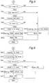
- the subroutine executed for this motor control determination by the motor control evaluation means 42 is described below with reference to the flow charts in Figs. 4 - 7. Note that unless otherwise specified, the process executed according to the flow charts in Figs. 4 - 7 is executed by the motor control evaluation means 42.
- the motor control evaluation means 42 first reads the high or low pressure state of the first and second pressure switches PSW1 and PSW2 (step S20), and determines whether the first pressure switch PSW1 is in a high pressure state (step S21). If the first pressure switch PSW1 is set to the high pressure state (step S21 returns YES), it is determined at step S22 whether the PSW1 correction flag is set; the PSW1 correction flag is used to correct the first pressure switch PSW1 to a low pressure state.
- step S22 If the PSW1 correction flag is set (step S22 returns YES), the pressure switch PSW1 is corrected so that the first pressure switch PSW1 indicates a low pressure state (step S23). It is then determined whether the second pressure switch PSW2 is set to a high pressure state (step S24).
- step S24 YES
- the PSW2 correction flag is used to correct the second pressure switch PSW2 to a high pressure state.
- step S27 If the PSW2 correction flag is set (step S27 returns YES), the second pressure switch PSW2 is reset (step S28), and it is again determined whether the first pressure switch PSW1 is set to a high pressure state (step S29).
- step S29 If the first pressure switch PSW1 is set to the high pressure state (step S29 returns YES), it is determined whether the second pressure switch PSW2 is set to a high pressure state after brake fluid pressure correction (step S32). If the second pressure switch PSW2 is set to a high pressure state (step S32 returns YES), control passes to step S33 of the subroutine shown in Fig. 5.
- step S36 It is then determined whether the value of the first timer 44 count is zero (0) (step S36). If it is zero (YES is returned), a problem is determined to exist in the first pressure switch PSW1 (step S37), the PSW1 correction flag is then set (step S38), the pump motor 17 is turned ON (step S39), and the control routine terminates.
- step S33 YES
- the pump motor 17 is then turned OFF (step S41) to stop the high pressure pump 16, and the control routine terminates.
- Control also flows to step S40 if the time indicated by the count of the second timer 45 is equal to predetermined value T2 (step S34), and if the value of the first timer 44 count is not zero (0) (step S36). In these cases, steps S40 and S41 are executed, and the control routine terminates.
- step S53 NO
- step S55 NO
- step S59 NO
- step S61 NO
- Fig. 8 is a system diagram of an expandable ABS apparatus using a booster in a four-wheel motor vehicle in which the control apparatus according to a second embodiment of the present invention is applied.
- Fig. 9 is a block diagram of a control apparatus for a fluid pressure circuit in automobiles according to this second embodiment of the invention. Note that like parts in Figs. 8 and 9 of this second embodiment and Figs. 1 and 2 of the first embodiment described above are identified by like reference numbers, and further description thereof is therefore omitted below.
- indices a, b, c, and d in the following description reference the front right, front left, rear right, and rear left wheels, respectively, in the following description of the second embodiment, such that 7a and 7b are the front right and left wheels, respectively, and 7c and 7d are the rear right and left wheels, respectively, in Fig. 8.
- the control computer 4A is connected to wheel speed sensors 60a, 60b, 60c, and 60d, which are provided at each vehicle wheel to detect the respective wheel speed; inlet valves 61a, 61b, 61c, and 61d, which are solenoid valves, function as two-position directional control valves; the solenoids for the outlet valves 62a, 62b, 62c, and 62d; the pump motor 17 for driving the high pressure pump 16; and an ON/OFF brake switch 67 connected to the brake pedal 10 for detecting when the brake pedal 10 is operated.
- the control computer 4A calculates the ABS control signal, which controls whether the brake fluid pressure is increased, decreased, or held steady, based on the respective wheel speeds calculated from the signal data supplied from the wheel speed sensors 60a - 60d, and controls the operation of the inlet valves 61a - 61d, outlet valves 62a - 62d, and the pump motor 17.
- a linear sensor whereby the output signal varies continuously according to the change in the stroke of the brake pedal may be used for the brake switch 67.
- Each of the inlet valves 61a - 61d and outlet valves 62a - 62d has two ports X and Y.
- the inlet valves 61a - 61d function as check valves and brake fluid flows from port X to port Y, and ports X and Y of the outlet valves 62a - 62d are closed.
- ports X and Y of the inlet valves 61a - 61d are closed, and ports X and Y of the outlet valves 62a - 62d are open.
- Ports X of the inlet valves 61a - 61d are connected to a common circuit that is in turn connected to the accumulator 15. Ports Y of the outlet valves 62a - 62d are similarly connected to a common circuit that is in turn connected to the hydraulic unit reserve tank 18. Ports Y of the inlet valves 61a - 61d are also connected to ports X of the outlet valves 62a - 62d. These junctions are further connected to port Z of the applied pressure diverters 63a - 63d, which function as two-position directional control valves, and to port S of the fluid pressure control chambers 64a - 64d. It is to be noted that applied pressure diverters 63a - 63d switch position according to the fluid pressure applied to port Z.
- Each of the applied pressure diverters 63a - 63d also has two ports X and Y, each port Y being connected to the corresponding wheel cylinder 70a - 70d.
- Port T of the fluid pressure control chambers 64a - 64d is connected to the line between the corresponding wheel cylinder 70a - 70d and port Y of the corresponding applied pressure diverters 63a - 63d.
- the applied pressure diverters 63a - 63d function as check valves, and the brake fluid flows from ports Y to ports X.
- ports X and Y of the applied pressure diverters 63a - 63d are through-connected, ports X of the front applied pressure diverters 63a and 63b are connected to the master cylinder 11, and ports X of the rear applied pressure diverters 63c and 63d are connected to the master cylinder 11 through the proportioning valves 69c and 69d; the proportioning valves 69c and 69d are for lowering the fluid pressure of the rear wheel cylinders 70c and 70d to below that of the front wheel cylinders 70a and 70b.
- Each of the fluid pressure control chambers 64a - 64d comprises an internal pressure reducing piston 65a - 65d.
- Ports S and T are disposed at the opposite ends of the direction of the pressure reducing piston stroke such that the pressure reducing pistons 65a - 65d move toward port T when the fluid pressure from the accumulator 15 is applied from port S, and move back toward port S when the pressure from port S is relieved.
- the hydraulic unit reserve tank 18 is connected through the check valve 71 to the high pressure pump 16, which is connected through check valve 72 to the accumulator 15.
- the one check valve 71 allows the brake fluid to flow only from the hydraulic unit reserve tank 18 to the high pressure pump 16
- the other check valve 72 allows the brake fluid to flow only from the high pressure pump 16 to the accumulator 15.
- the first pressure switch PSW1, which functions as the first fluid pressure detection means of the Claims, and the second pressure switch PSW2, which functions as the second fluid pressure detection means of the Claims, are connected to the line between the one check valve 72 and the accumulator 15.
- the first and second pressure switches PSW1 and PSW2 detect the fluid pressure of the accumulator 15, and can each indicate two states, high and low pressure states, relative to the respective fluid pressure settings.
- the first and second pressure switches PSW1 and PSW2 are also connected to the control computer 4A, and output the respective detected pressure states to the control computer 4A.
- the brake fluid pressure stored in the accumulator 15, which is the high brake fluid pressure source, is supplied to the booster 68 when the brake pedal 10 is pressed.
- the applied brake pressure pushes the piston (not shown in the figures) inside the master cylinder 11, thus pressurizing the brake fluid supplied from the hydraulic unit reserve tank 18 and applying the brake fluid pressure to ports X of the applied pressure diverters 63a - 63d.
- the fluid pressure from the booster 68 is applied to the hydraulic unit reserve tank 18, and the fluid pressure acting on the piston inside the master cylinder 11 drops.
- the master cylinder piston is thus returned, lowering the fluid pressure inside the master cylinder 11, and thereby lowering the pressure applied to ports X of the applied pressure diverters 63a - 63d.
- the control computer 4A supplies current to the solenoids of the inlet valves 61a - 61d and the outlet valves 62a - 62d, thereby causing both valve sets to switch.
- the inlet valves 61a - 61d are thus cut off by the fluid pressure from the accumulator 15, and the brake fluid in the fluid pressure control chambers 64a - 64d flows from ports S through the outlet valves 62a - 62d and into the hydraulic unit reserve tank 18.
- the applied pressure diverters 63a - 63d switch and function as check valves, shutting off the flow of brake fluid from the master cylinder 11 to the wheel cylinders 70a - 70d.
- the pressure reducing pistons 65a - 65d thus also move to the port S side, allowing the brake fluid in the wheel cylinders 70a - 70d to flow into the fluid pressure control chambers 64a - 64d, reducing the brake fluid pressure in the wheel cylinders 70a - 70d, and reducing the brake pressure acting on each of the wheel brakes.
- the control computer 4A supplies current to the solenoids of the inlet valves 61a - 61d, which thus assume the energized state (ports X and Y are closed), and interrupts the current supply to the outlet valves 62a - 62d, which thus assume the non-energized state (ports X and Y are closed). This stops the flow of brake fluid through the fluid pressure control chambers 64a - 64d, and thus holds the brake fluid pressure at each wheel cylinder 70a - 70d constant.
- control apparatus for a motor vehicle fluid pressure circuit is described below with reference to the block diagram shown in Fig. 9. It is assumed below that this control apparatus is used in an ABS system as shown in Fig. 8.
- the pressure reducer 50A for increasing, decreasing, or holding the brake fluid pressure and shown in Fig. 2 comprises the inlet valves 61a - 61d, outlet valves 62a - 62d, applied pressure diverters 63a - 63d, and fluid pressure control chambers 64a - 64d shown in Fig. 8, but is treated below as a single apparatus for simplicity alone.
- the control computer 4A calculates the brake fluid pressure control command value, which is the control signal applied to the pressure reducer 50A, based on the data received from the wheel speed sensors 60a - 60d, the brake switch 67, and the first and second pressure switches PSW1 and PSW2, and outputs this value to the pressure reducer 50A.
- the control computer 4A also outputs the control signal to the pump motor 17 driving the high pressure pump 16.
- control computer 4A comprises, as shown in Fig. 9, a wheel speed calculator 80, antilock controller 81, pressure reducer drive means 41A, motor control evaluation means 42A, and motor driver 43A.
- the wheel speed calculator 80 calculates the speed of each wheel based on the signal data received from the wheel speed sensors 60a - 60d.
- the antilock controller 81 determines whether ABS control is required based on the wheel speeds calculated by the wheel speed calculator 80, and outputs the appropriate ABS control request signal when ABS control is required.
- the pressure reducer drive means 41A calculates the brake fluid pressure control command value in response to the ABS control request signal from the antilock controller 81, and drives the pressure reducer 50A using this command value.
- the motor control evaluation means 42A determines whether the pump motor 17 should be ON or OFF based on the ABS control request signal from the antilock controller 81 and the signal data from the brake switch 67 and the first and second pressure switches PSW1 and PSW2.
- the motor driver 43A then drives the pump motor 17 based on the evaluation signal output from the motor control evaluation means 42A.
- the motor control evaluation means 42A further comprises a first timer 44 for counting the time during which the first pressure switch PSW1 indicates a low pressure state, and a second timer 45 for counting the time during which the second pressure switch PSW2 indicates a low pressure state, and functions as the trouble evaluation means and the pump drive evaluation means of the Claims.
- the wheel speed calculator 80 calculates the speed of each wheel based on the signal data from the wheel speed sensors 60a - 60d, and outputs the result to the antilock controller 81.
- the antilock controller 81 is connected to the pressure reducer drive means 41A and the motor control evaluation means 42A, and outputs the ABS control request signal to the pressure reducer drive means 41A and motor control evaluation means 42A when it is determined to apply ABS control based on each of the wheel speeds calculated by the wheel speed calculator 80.
- the pressure reducer drive means 41A is further connected to the pressure reducer 50A, computes the brake fluid pressure control command value according to the ABS control request signal input from the antilock controller 81, and outputs the command value to the pressure reducer 50A.
- the brake fluid pressure is thus controlled by the pressure reducer 50A to control the vehicle braking force. Note that the wheel speed, ABS control request signal, and brake fluid pressure control command value are calculated by methods known in the literature, and further description thereof is thus omitted below.
- the motor control evaluation means 42A is further connected to the brake switch 67, the first and second pressure switches PSW1 and PSW2, and the motor driver 43A, determines whether pump motor control is required based on the ABS control request signal from the antilock controller 81 and the signal data from the brake switch 67 and the first and second pressure switches PSW1 and PSW2, and outputs the result to the motor driver 43A.
- the motor driver 43A is further connected to the pump motor 17, and can thus control the pump motor 17 in response to the signal supplied from the motor control evaluation means 42A.
- ABS control request signal output from the antilock controller 81 to the motor control evaluation means 42A causes the pump motor 17 to switch ON; when the second pressure switch PSW2 indicates a low pressure state, the motor control evaluation means 42A outputs a signal prohibiting ABS control to the antilock controller 81.
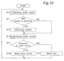
- the wheel speed calculator 80 first calculates the wheel speed of each wheel based on the signal data from the wheel speed sensors 60a - 60d, and outputs the results to the antilock controller 81 (step S10).
- the antilock controller 81 detects whether the signal prohibiting ABS control has been input from the motor control evaluation means 42A due to a low pressure state (step S11), i.e., determines whether ABS control is permitted by the motor control evaluation means 42A.
- step S11 YES
- Whether pump motor control is to be applied is then determined by the motor control evaluation means 42A (step S13).
- the subroutine executed by the motor control evaluation means 42A to determine whether to apply pump motor control is similar to that executed by the motor control evaluation means 42 of the first embodiment and described above with reference to Figs. 4 - 7.
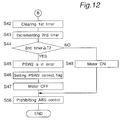
- the motor control evaluation means 42A executes the procedure shown in the flow chart in Fig. 4, Fig. 11 is substituted for Fig. 5, Fig. 12 is substituted for Fig. 6, and Fig. 13 is substituted for Fig. 7.
- the motor control evaluation routine of the second embodiment is described below with reference to Figs. 11 - 13.
- the flow chart in Fig. 11 differs from that in Fig. 5 in that the processes in Fig. 5 executed by the motor control evaluation means 42 are executed by the motor control evaluation means 42A, and step S65 is added after steps S39 and S41 in Fig. 5.
- step S65 After both steps S39 and S41 in Fig. 11, it is determined to permit ABS control (step S65), and the routine terminates without outputting the ABS control prohibit signal to the antilock controller 81.
- the flow chart in Fig. 12 differs from that in Fig. 6 in that the processes in Fig. 6 executed by the motor control evaluation means 42 are executed by the motor control evaluation means 42A, and step S66 is added after steps S47 and S48 in Fig. 6.
- step S66 After both steps S47 and S48 in Fig. 12, it is determined to prohibit ABS control (step S66), the ABS control prohibit signal is output to the antilock controller 81, and the routine terminates.
- the flow chart in Fig. 13 differs from that in Fig. 7 in that the processes in Fig. 7 executed by the motor control evaluation means 42 are executed by the motor control evaluation means 42A, the evaluation process shown as step S55 in Fig. 7 is replaced by the evaluation process shown in step S70 in Fig. 13, the evaluation process shown as step S61 in Fig. 7 is replaced by the evaluation process shown in step S71 in Fig. 13, step S65 in Fig. 13 is added after steps S56 and S57 in Fig. 7, and step S66 in Fig. 13 is added after steps S62 and S63 in Fig. 7.
- pressure switches indicating a high or low pressure state relative to the respective fluid pressure settings are used as the pressure detection means. It is also possible, however, to use linear sensors whereby the output signal varies continuously according to the change in the brake fluid pressure. Furthermore, ABS control is prohibited in the second embodiment above when the second pressure switch PSW2 indicates a low pressure state, but it is also possible to prohibit ABS control when a problem is detected in the high pressure pump 16 (including problems in the pump motor 17), or in the first or second pressure switches PSW1 and PSW2.
Landscapes
- Engineering & Computer Science (AREA)
- Transportation (AREA)
- Mechanical Engineering (AREA)
- Physics & Mathematics (AREA)
- Fluid Mechanics (AREA)
- Valves And Accessory Devices For Braking Systems (AREA)
- Regulating Braking Force (AREA)
Applications Claiming Priority (3)
| Application Number | Priority Date | Filing Date | Title |
|---|---|---|---|
| JP304714/94 | 1994-12-08 | ||
| JP30471494 | 1994-12-08 | ||
| JP30471494A JP3914581B2 (ja) | 1994-12-08 | 1994-12-08 | 車両用液圧回路の制御装置 |
Publications (3)
| Publication Number | Publication Date |
|---|---|
| EP0716003A2 true EP0716003A2 (de) | 1996-06-12 |
| EP0716003A3 EP0716003A3 (de) | 1998-09-16 |
| EP0716003B1 EP0716003B1 (de) | 2000-03-08 |
Family
ID=17936333
Family Applications (1)
| Application Number | Title | Priority Date | Filing Date |
|---|---|---|---|
| EP95119225A Expired - Lifetime EP0716003B1 (de) | 1994-12-08 | 1995-12-06 | Überwachungseinrichtung für einen Kraftfahrzeug-Druckflüssigkeitskreis |
Country Status (5)
| Country | Link |
|---|---|
| US (1) | US5695260A (de) |
| EP (1) | EP0716003B1 (de) |
| JP (1) | JP3914581B2 (de) |
| KR (1) | KR100187599B1 (de) |
| DE (1) | DE69515431T2 (de) |
Cited By (2)
| Publication number | Priority date | Publication date | Assignee | Title |
|---|---|---|---|---|
| EP0937621A3 (de) * | 1998-02-21 | 2000-08-16 | Robert Bosch Gmbh | Verfahren und Vorrichtung zur Steuerung einer Bremsanlage |
| GB2347981A (en) * | 1999-03-05 | 2000-09-20 | Lucas Industries Ltd | Electro-hydraulic braking systems |
Families Citing this family (7)
| Publication number | Priority date | Publication date | Assignee | Title |
|---|---|---|---|---|
| SE507414C2 (sv) * | 1996-03-04 | 1998-05-25 | Volvo Wheel Loaders Ab | Hydrauliskt fordonsbromssystem |
| JP3528415B2 (ja) * | 1996-04-23 | 2004-05-17 | トヨタ自動車株式会社 | 制動圧力制御装置 |
| JPH11124025A (ja) * | 1997-10-24 | 1999-05-11 | Toyota Motor Corp | ブレーキ装置のアキュムレータ圧力の推定方法 |
| DE19828552C1 (de) * | 1998-06-26 | 2000-02-03 | Bosch Gmbh Robert | Verfahren und Vorrichtung zur Bildung eines Ansteuersignals zur Ansteuerung einer Pumpe zur Förderung eines Druckmediums in einem Fahrzeugbremssystem |
| JP4560919B2 (ja) * | 2000-08-30 | 2010-10-13 | 株式会社アドヴィックス | 車両の液圧ブレーキ装置 |
| US8012063B2 (en) * | 2007-03-02 | 2011-09-06 | GM Global Technology Operations LLC | Pressure assisted park servo |
| FR3083194B1 (fr) * | 2018-06-28 | 2021-06-25 | Poclain Hydraulics Ind | Procede et systeme de freinage hydraulique ameliore pour vehicule avec attelage |
Family Cites Families (7)
| Publication number | Priority date | Publication date | Assignee | Title |
|---|---|---|---|---|
| DE3444458C2 (de) * | 1984-12-06 | 1995-06-29 | Teves Gmbh Alfred | Schaltungsanordnung zur Überwachung und Steuerung des Druckes im Hilfsdruck-Versorgungssystem einer hydraulischen Kraftfahrzeug-Bremsanlage |
| DE3538120A1 (de) * | 1985-10-26 | 1987-04-30 | Teves Gmbh Alfred | Druckversorgungssystem, insbesondere fuer kraftfahrzeugbremsanlagen |
| DE3833473A1 (de) * | 1988-10-01 | 1990-04-05 | Teves Gmbh Alfred | Schaltungsanordnung zur steuerung der hydraulikpumpe des hilfsdruckversorgungssystems einer kraftfahrzeug-bremsanlage |
| JPH03266756A (ja) * | 1990-03-15 | 1991-11-27 | Honda Motor Co Ltd | アンチロック制御装置 |
| GB2245038B (en) * | 1990-06-07 | 1994-03-23 | Toyota Motor Co Ltd | Device for detecting accumulator fluid leakage through control valve and restoring proper valve seating |
| JP2762171B2 (ja) * | 1991-01-09 | 1998-06-04 | 本田技研工業株式会社 | 圧力機器用圧力源 |
| JPH0680064A (ja) * | 1992-07-13 | 1994-03-22 | Sumitomo Electric Ind Ltd | 液圧制御装置 |
-
1994
- 1994-12-08 JP JP30471494A patent/JP3914581B2/ja not_active Expired - Fee Related
-
1995
- 1995-12-01 US US08/565,820 patent/US5695260A/en not_active Expired - Fee Related
- 1995-12-06 DE DE69515431T patent/DE69515431T2/de not_active Expired - Fee Related
- 1995-12-06 EP EP95119225A patent/EP0716003B1/de not_active Expired - Lifetime
- 1995-12-07 KR KR1019950047274A patent/KR100187599B1/ko not_active Expired - Fee Related
Non-Patent Citations (1)
| Title |
|---|
| None |
Cited By (4)
| Publication number | Priority date | Publication date | Assignee | Title |
|---|---|---|---|---|
| EP0937621A3 (de) * | 1998-02-21 | 2000-08-16 | Robert Bosch Gmbh | Verfahren und Vorrichtung zur Steuerung einer Bremsanlage |
| US6679569B2 (en) | 1998-02-21 | 2004-01-20 | Robert Bosch Gmbh | Method and device for controlling a brake system |
| GB2347981A (en) * | 1999-03-05 | 2000-09-20 | Lucas Industries Ltd | Electro-hydraulic braking systems |
| GB2347981B (en) * | 1999-03-05 | 2003-01-22 | Lucas Industries Ltd | Electro-hydraulic braking systems |
Also Published As
| Publication number | Publication date |
|---|---|
| DE69515431D1 (de) | 2000-04-13 |
| KR960022035A (ko) | 1996-07-18 |
| KR100187599B1 (ko) | 1999-06-01 |
| JPH08156781A (ja) | 1996-06-18 |
| EP0716003B1 (de) | 2000-03-08 |
| US5695260A (en) | 1997-12-09 |
| EP0716003A3 (de) | 1998-09-16 |
| JP3914581B2 (ja) | 2007-05-16 |
| DE69515431T2 (de) | 2000-08-03 |
Similar Documents
| Publication | Publication Date | Title |
|---|---|---|
| CN100422008C (zh) | 横向动稳性控制系统 | |
| JP3878229B2 (ja) | 車両の減速度制御装置 | |
| US4880282A (en) | Braking system with apparatus for controlling pressure to be accumulated in accumulator for braking motor vehicle | |
| EP2039573B1 (de) | Vorrichtung zur Regelung des Fahrverhaltens eines Fahrzeugs | |
| US6007164A (en) | Brake fluid pressure control apparatus for compensating a malfunction of brake operational force sensor | |
| EP0703118B1 (de) | Kraftfahrzeug-Bremskraftsteuergerät | |
| JP2952798B2 (ja) | 流体圧システムおよび車両用流体圧ブレーキシステムにおける故障検出方法 | |
| EP0716003B1 (de) | Überwachungseinrichtung für einen Kraftfahrzeug-Druckflüssigkeitskreis | |
| JPH11348759A (ja) | 自動車ブレ―キ装置の制御方法および装置 | |
| JPH036019B2 (de) | ||
| US4789938A (en) | Anti-skid control with fail-safe function | |
| US5752751A (en) | Anti-skid control apparatus with brake failure detection means | |
| JPH0790765B2 (ja) | アンチロックブレ−キ装置用故障検出回路 | |
| US6302501B1 (en) | Method and apparatus for controlling the brake system of a vehicle | |
| US20070046098A1 (en) | Vehicle stability system diagnostic method | |
| JPH03200462A (ja) | アンチスキッド制御装置 | |
| US20010034574A1 (en) | Vehicular brake conrol device | |
| US6120112A (en) | Brake pressure control device for vehicle | |
| JP3867308B2 (ja) | 液圧制御装置の故障検出方法 | |
| JP3938830B2 (ja) | ブレーキ制御装置 | |
| JPH01269656A (ja) | 自動車用故障判定装置を用いるアンチスキッド制御装置 | |
| JP4432237B2 (ja) | 車両用制動制御装置 | |
| JP2001219845A (ja) | 制動力制御装置 | |
| JP3183113B2 (ja) | 車輌の制動力制御装置 | |
| JP2767939B2 (ja) | 電源監視装置 |
Legal Events
| Date | Code | Title | Description |
|---|---|---|---|
| PUAI | Public reference made under article 153(3) epc to a published international application that has entered the european phase |
Free format text: ORIGINAL CODE: 0009012 |
|
| AK | Designated contracting states |
Kind code of ref document: A2 Designated state(s): DE FR GB |
|
| RIN1 | Information on inventor provided before grant (corrected) |
Inventor name: YOSHINO, MASATO, C/O ITAMI WORKS OF SUMITOMO Inventor name: TANAKA, HIROHISA, C/O ITAMI WORKS OF SUMITOMO |
|
| PUAL | Search report despatched |
Free format text: ORIGINAL CODE: 0009013 |
|
| 17P | Request for examination filed |
Effective date: 19980715 |
|
| AK | Designated contracting states |
Kind code of ref document: A3 Designated state(s): DE FR GB |
|
| 17Q | First examination report despatched |
Effective date: 19981001 |
|
| GRAG | Despatch of communication of intention to grant |
Free format text: ORIGINAL CODE: EPIDOS AGRA |
|
| GRAG | Despatch of communication of intention to grant |
Free format text: ORIGINAL CODE: EPIDOS AGRA |
|
| GRAH | Despatch of communication of intention to grant a patent |
Free format text: ORIGINAL CODE: EPIDOS IGRA |
|
| GRAH | Despatch of communication of intention to grant a patent |
Free format text: ORIGINAL CODE: EPIDOS IGRA |
|
| GRAA | (expected) grant |
Free format text: ORIGINAL CODE: 0009210 |
|
| AK | Designated contracting states |
Kind code of ref document: B1 Designated state(s): DE FR GB |
|
| REF | Corresponds to: |
Ref document number: 69515431 Country of ref document: DE Date of ref document: 20000413 |
|
| ET | Fr: translation filed | ||
| PGFP | Annual fee paid to national office [announced via postgrant information from national office to epo] |
Ref country code: GB Payment date: 20001206 Year of fee payment: 6 |
|
| PGFP | Annual fee paid to national office [announced via postgrant information from national office to epo] |
Ref country code: FR Payment date: 20001212 Year of fee payment: 6 |
|
| PLBE | No opposition filed within time limit |
Free format text: ORIGINAL CODE: 0009261 |
|
| STAA | Information on the status of an ep patent application or granted ep patent |
Free format text: STATUS: NO OPPOSITION FILED WITHIN TIME LIMIT |
|
| 26N | No opposition filed | ||
| PG25 | Lapsed in a contracting state [announced via postgrant information from national office to epo] |
Ref country code: GB Free format text: LAPSE BECAUSE OF NON-PAYMENT OF DUE FEES Effective date: 20011206 |
|
| REG | Reference to a national code |
Ref country code: GB Ref legal event code: IF02 |
|
| GBPC | Gb: european patent ceased through non-payment of renewal fee |
Effective date: 20011206 |
|
| PG25 | Lapsed in a contracting state [announced via postgrant information from national office to epo] |
Ref country code: FR Free format text: LAPSE BECAUSE OF NON-PAYMENT OF DUE FEES Effective date: 20020830 |
|
| REG | Reference to a national code |
Ref country code: FR Ref legal event code: ST |
|
| PGFP | Annual fee paid to national office [announced via postgrant information from national office to epo] |
Ref country code: DE Payment date: 20071129 Year of fee payment: 13 |
|
| PG25 | Lapsed in a contracting state [announced via postgrant information from national office to epo] |
Ref country code: DE Free format text: LAPSE BECAUSE OF NON-PAYMENT OF DUE FEES Effective date: 20090701 |