EP0716006A2 - Méthode et véhicule à chenilles pour circuler sur une surface magnétique - Google Patents
Méthode et véhicule à chenilles pour circuler sur une surface magnétique Download PDFInfo
- Publication number
- EP0716006A2 EP0716006A2 EP95250299A EP95250299A EP0716006A2 EP 0716006 A2 EP0716006 A2 EP 0716006A2 EP 95250299 A EP95250299 A EP 95250299A EP 95250299 A EP95250299 A EP 95250299A EP 0716006 A2 EP0716006 A2 EP 0716006A2
- Authority
- EP
- European Patent Office
- Prior art keywords
- vehicle
- caterpillar
- magnets
- magnetic
- vehicle according
- Prior art date
- Legal status (The legal status is an assumption and is not a legal conclusion. Google has not performed a legal analysis and makes no representation as to the accuracy of the status listed.)
- Withdrawn
Links
- 238000000034 method Methods 0.000 title claims description 19
- 230000003472 neutralizing effect Effects 0.000 claims abstract description 7
- 238000005422 blasting Methods 0.000 claims description 29
- 238000003754 machining Methods 0.000 claims description 6
- 238000012544 monitoring process Methods 0.000 claims description 4
- 239000000725 suspension Substances 0.000 claims description 4
- 238000007789 sealing Methods 0.000 claims description 2
- 230000014759 maintenance of location Effects 0.000 abstract 1
- 230000005284 excitation Effects 0.000 description 19
- 239000000463 material Substances 0.000 description 9
- 239000000853 adhesive Substances 0.000 description 7
- 230000001070 adhesive effect Effects 0.000 description 7
- 238000012545 processing Methods 0.000 description 4
- 238000003860 storage Methods 0.000 description 4
- 238000004140 cleaning Methods 0.000 description 3
- 238000007689 inspection Methods 0.000 description 2
- 230000007935 neutral effect Effects 0.000 description 2
- 238000006386 neutralization reaction Methods 0.000 description 2
- 229910052782 aluminium Inorganic materials 0.000 description 1
- XAGFODPZIPBFFR-UHFFFAOYSA-N aluminium Chemical compound [Al] XAGFODPZIPBFFR-UHFFFAOYSA-N 0.000 description 1
- 239000011324 bead Substances 0.000 description 1
- 230000005540 biological transmission Effects 0.000 description 1
- 239000011248 coating agent Substances 0.000 description 1
- 238000000576 coating method Methods 0.000 description 1
- 238000010276 construction Methods 0.000 description 1
- 238000013461 design Methods 0.000 description 1
- 230000004907 flux Effects 0.000 description 1
- 230000001939 inductive effect Effects 0.000 description 1
- 230000005415 magnetization Effects 0.000 description 1
- 230000009347 mechanical transmission Effects 0.000 description 1
- 229910052751 metal Inorganic materials 0.000 description 1
- 239000002184 metal Substances 0.000 description 1
- 238000012806 monitoring device Methods 0.000 description 1
- 230000003287 optical effect Effects 0.000 description 1
- 238000010422 painting Methods 0.000 description 1
- 239000006223 plastic coating Substances 0.000 description 1
- 230000000717 retained effect Effects 0.000 description 1
- 238000005488 sandblasting Methods 0.000 description 1
- 230000035939 shock Effects 0.000 description 1
- 238000005507 spraying Methods 0.000 description 1
- 229910001220 stainless steel Inorganic materials 0.000 description 1
- 239000010935 stainless steel Substances 0.000 description 1
- 238000012360 testing method Methods 0.000 description 1
- 230000001960 triggered effect Effects 0.000 description 1
Images





Classifications
-
- B—PERFORMING OPERATIONS; TRANSPORTING
- B63—SHIPS OR OTHER WATERBORNE VESSELS; RELATED EQUIPMENT
- B63B—SHIPS OR OTHER WATERBORNE VESSELS; EQUIPMENT FOR SHIPPING
- B63B59/00—Hull protection specially adapted for vessels; Cleaning devices specially adapted for vessels
- B63B59/06—Cleaning devices for hulls
- B63B59/10—Cleaning devices for hulls using trolleys or the like driven along the surface
-
- B—PERFORMING OPERATIONS; TRANSPORTING
- B62—LAND VEHICLES FOR TRAVELLING OTHERWISE THAN ON RAILS
- B62D—MOTOR VEHICLES; TRAILERS
- B62D55/00—Endless track vehicles
- B62D55/08—Endless track units; Parts thereof
- B62D55/18—Tracks
- B62D55/26—Ground engaging parts or elements
- B62D55/265—Ground engaging parts or elements having magnetic or pneumatic adhesion
Definitions
- the invention relates to a method for driving on magnetic surfaces with a caterpillar vehicle according to the preamble of claim 1 and a caterpillar vehicle for driving on magnetic surfaces according to the preamble of claim 5.
- Such caterpillars can be used for cleaning, sandblasting, painting or testing welds even on vertical or overhanging magnetic surfaces. For this, they are provided with suitable accessories, such as brushes, spraying, blasting devices or monitoring devices.
- DE-PS 2 023 683 discloses a vehicle with magnetic traction, which has two laterally arranged magnetic devices, around which endless drive belts are guided, and in the center of which an additional magnetic device is arranged.
- the magnetic device located in the center of the vehicle automatically adjusts its vertical movement to the surface and thus creates a constant adhesive force between the vehicle and the surface to be driven on.
- uneven floors, such as. B. welds, rivets or overlapping plates are poorly balanced due to the rigid mounting of the drive belt. With such bumps there is a risk that the vehicle will tip off the surface due to weak adhesive forces.
- the vehicle can be rotated about the magnetic device arranged around the center via an additional drive.
- the published patent application DE-OS 2 413 688 describes a crawler vehicle for driving on vertical walls and ceilings. Depending on the surface to be driven on, this vehicle is equipped with magnets or vacuum devices on the caterpillars.
- the known crawler vehicles described above are alternatively provided with electric or permanent magnets for adhering to the magnetic surface. In both cases, a large amount of energy must be used in order to achieve a sufficiently high adhesive force.
- electromagnets are used as an adhesive, electrical energy must be continuously supplied in order to ensure secure adhesion. This is both disadvantageous in terms of energy and also disadvantageous in terms of safety, since the vehicle must be secured against sudden power failure.
- the invention has for its object to provide a method and a crawler vehicle for driving on magnetic surfaces, which avoids the disadvantages mentioned.
- security measures against power failure should be made largely unnecessary and the removal of the caterpillar vehicle from the surface should be facilitated.
- a method and a caterpillar vehicle for driving on magnetic surfaces are created to achieve this object, the holding force being generated by means of holding magnets which are designed as permanent electromagnets (permanently magnetically excited, electrically switchable magnets).
- Permanent electromagnets are a hybrid of permanent and electromagnets, in which on the one hand a magnetic force is retained in the magnetized state even without a power supply and on the other hand the magnetic force can be neutralized by applying an excitation current.
- a coil is wound around a magnetic core, via which an excitation current can induce a magnetic force.
- the magnetic core can be designed to be permanently magnetic.
- the permanent electromagnet is neutralized when the magnetic force induced by the excitation current counteracts and compensates for the magnetic force of the permanent magnetic core.
- the magnetic core is polarizable, so that it polarizes by means of the excitation current, i.e. can be magnetized. By means of an opposite excitation current, the polarized permanent magnet material can be neutralized again, i.e. be demagnetized.
- the properties of the permanent electromagnets can advantageously be used for the method according to the invention.
- a permanent force is generated by the permanent electromagnets, which the caterpillar vehicle can hold on the magnetic surface without any energy supply, which makes safety measures against power failure unnecessary.
- An energy saving compared to previous crawler vehicles results from the fact that only the excitation current generates a power loss.
- the permanent electromagnets can be neutralized at any time, which, for example, prevents the magnetic forces from being overcome when the caterpillar vehicle is removed from the magnetic surface.
- a caterpillar vehicle with two caterpillars, each having a caterpillar track, in which the holding magnets are arranged on or in the caterpillar tracks, is preferably used to carry out the method according to the invention, with the holding magnets at the front end of the caterpillar vehicle during driving operation when it is placed on the surface in a neutralized state and magnetized after being placed on the surface and the holding magnets at the rear end of the caterpillar vehicle are neutralized before removal from the surface.
- This enables a low-impact attachment and a force-free tipping of the chain links.
- the holding magnets are only neutralized and magnetized for a short time, which is why only a small amount of electrical power has to be supplied when driving.
- the caterpillars of the caterpillar vehicle are preferably fastened to a load carrying frame which is rotatably mounted about auxiliary magnets.
- auxiliary magnets To change the direction of travel, one or more auxiliary magnets are activated, the holding magnets are neutralized and the load carrying frame is rotated by means of an auxiliary drive. This enables precise control of the vehicle, since influences of the surface properties on the turning process are reduced.
- a caterpillar vehicle with which in particular the method according to the invention can be carried out is characterized by the features of claim 5.
- the adhesives can be easily mounted on the caterpillar vehicle if the holding magnets are arranged on the chain links of the caterpillar chain.
- Sliding contacts can be used as an inexpensive means of neutralizing the holding magnets.
- the load carrying frame of the caterpillar vehicle is rotatably mounted about auxiliary magnets which can carry the weight of the caterpillar vehicle. Changes in direction can be carried out precisely by means of an auxiliary drive which can rotate the load carrier frame.
- the backing of the caterpillar vehicle when stopping can be avoided by self-locking the drive.
- the chain links are preferably flexibly supported by a pendulum suspension to compensate for unevenness.
- means for monitoring the surface quality are provided at both ends of the crawler vehicle. As a result, the vehicle can be stopped and accidents avoided if non-magnetic ground is detected. At the same time, surface monitoring can be used for demanding surface processing or for surface inspection.
- the tensile stress on the supply lines can be measured with a measuring apparatus. If the pulling force is too high, the vehicle can be stopped to prevent accidents.
- a blasting device is provided on the crawler vehicle.
- This blasting device comprises a blasting bell into which the blasting hose with the blasting nozzle is passed through a blasting hose bushing, a suction nozzle and plastic bristles for sealing the blasting bell. This allows the vehicle to be used cheaply for cleaning magnetic surfaces.
- the size of the machining surface can be adjusted via the eccentric drive.
- the caterpillar vehicle according to the invention shown in FIG. 1a has two independently driven caterpillars 10, each with a caterpillar track 19 (see FIG. 1c).
- the caterpillars 10 are fastened to the load carrying frame 12 with a quick connection 11.
- a turntable 14 is welded onto the load bearing frame 12, in which the guide rollers 15 are guided.
- the guide rollers 15 are mounted on a retaining ring 18 on which the auxiliary magnets 13 are also attached.
- the auxiliary drive 17 is arranged on the load carrying frame 12 with a rotating device, not shown in detail.
- FIG. 1b shows an enlarged section through part of the caterpillar vehicle according to FIG. 1a.
- the guide roller 15 is guided on the turntable 14.
- the slewing ring 14, together with the load-bearing frame 12, is rotatably mounted about the holding ring 18.
- FIG. 1c shows a caterpillar 10 of the caterpillar vehicle on a magnetic surface 30 in a side view.
- a mounting plate 34 On a mounting plate 34, three gears 32, 33, 35 for guiding the crawler belt 19 are arranged.
- the crawler belt 19 made of stainless steel has on its chain links double-row holding magnets 31, which are permanent electromagnets.
- the permanent electromagnets are designed, for example, as neutralizable permanent magnets.
- the permanent magnetic core is surrounded by a coil, via which an excitation current can be used to induce a magnetic force which counteracts the magnetic force of the permanent magnet.
- the induced magnetic force can neutralize the magnetic force of the permanent magnet.
- the front holding magnet 37 which comes next into contact with the machining surface, is briefly neutralized by means of a sliding contact (not shown) by an excitation current (neutralization area) in order to achieve a gentle placement of the holding magnet on the surface.
- the rear holding magnet 38 is also neutralized by another sliding contact before it is tipped over by the magnetic surface 30.
- the number of the holding magnets on the magnetic surface 30 is determined by the weight of the crawler vehicle and the tool to be picked up, a secure holding force having to be ensured. Small caterpillar vehicles for driving on pipes and large caterpillar vehicles for carrying scaffolding are conceivable.
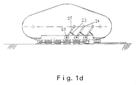
- the chain links are guided on the magnetic surface 30 by means of a pendulum suspension shown in FIG. 1d so that unevenness can also be compensated for.
- This storage for caterpillar tracks is generally usable for caterpillar vehicles.
- the chain links are guided over bearing rollers 22 during contact with the surface.
- the bearing rollers are arranged on pivot bearings 24 mounted pendulum rods 21.
- the pendulum rods are acted upon by springs 23 with a spring force. If there is a depression in the surface, the chain links are pressed into the depression at this point via the bearing roller 22. When the surface bulges out, the chain links press on the bearing rollers 22 at this point.
- the bearing rollers 22 compensate for the unevenness with a lever-like movement upwards.
- the pendulum suspension has the advantage that a large contact area of the holding magnets 31 guided on the crawler belt 19 with the magnetic surface 30 is ensured even in the event of unevenness.
- the holding magnets 31, which are located on the magnetic surface 30, are acted upon by an excitation current (for example via additional sliding contacts), so that the holding magnets 31 are in a neutralized state.
- the caterpillar vehicle can then be removed from the surface without being overcome by magnetic forces and can be placed on the surface.
- the caterpillar vehicle is stopped and the auxiliary magnets 13 are excited so that they ensure that the caterpillar vehicle adheres securely to the magnetic surface 30.
- the holding magnets 31 which are located in In contact with the magnetic surface.
- the auxiliary drive 17 then rotates the load carrying frame 12 about the holding ring 18 provided with a toothed ring to the desired position (not shown) via a toothed pinion with a chain located on its output shaft. This means that the caterpillar vehicle has an extremely small turning radius.
- the excitation current which neutralizes the holding magnets 31 in contact with the magnetic surface 30, is switched off, the auxiliary magnets 13 are deactivated and the driving operation can be continued.
- the caterpillar tracks are driven electrically by a maintenance-free brushless servo motor and are floor-controlled and programmable.
- the speed is infinitely adjustable and is transmitted to the two drive gears 32 and 35 via a mechanical transmission system.
- the power and speed of the crawler vehicle to be transmitted can be determined via the freely selectable spindle pitch and the transmission ratio.
- the possible speed range is usually up to 10 m / min in a preferred embodiment of the invention.
- the drives are self-locking, which is why the crawler vehicle can be stopped in a non-return manner.
- Both caterpillar chain drives are constructed identically and can travel curved sections using different speed settings.
- the caterpillar vehicle is equipped with sensors at the front and rear end, with which a redundant check of the distance and nature of the surface is carried out.
- Inductive proximity sensors as well as capacitive and optical sensors are used as sensors. If the surface is not magnetic or the air gap is too large, e.g. B. occurs due to plastic coating or the use of aluminum plates, a fault message is triggered and the vehicle is immediately stopped.
- image monitoring is also provided, with which surface inspections or sophisticated surface processing can be carried out.
- sliding contacts 70a, 70b for neutralizing or magnetizing the holding magnets 31 is shown schematically in FIG. 1e.
- the sliding contacts 70a, 70b are attached to the frame of the caterpillar 10. They contact holding magnets 39 and 38, which are being placed on magnetic surface 30 or are being lifted off of it.
- polarizable permanent electromagnets are used as a basis. These permanent electromagnets can be magnetized as well as neutralized by a short-term excitation current, the respective state being maintained until the next excitation current. On the one hand, this can be achieved in that the magnetic core consists of a suitable polarizable material. On the other hand, such a permanent electromagnet can also comprise two adjacent permanent magnets of the same type, one of which is surrounded by a coil. The magnetization direction of this magnet can be set by energizing the coil. Depending on whether this permanent magnet is magnetized parallel or antiparallel to the other, the entire permanent electromagnet is either magnetic or neutral.
- the holding magnet 37 designed as a permanent electromagnet is in a neutralized state when it is placed on the magnetic surface 30. This ensures that no shocks from the magnetic attraction force occur when the holding magnet 37 is put on.
- the holding magnet 37 is neutralized with another (not shown) sliding contact shortly before it is placed on the surface 30.
- the holding magnets which are always neutralized at position 70b before being lifted off the magnetic surface 30, to remain in a neutralized state continuously until they are again placed on the magnetic surface at the front end of the bead. In this case, no additional sliding contact for briefly neutralizing at the front end of the caterpillar 10 is necessary.
- a holding magnet 39 As soon as a holding magnet 39 is placed on the surface 30, it is magnetized by energization by means of the sliding contact 70a.
- the holding magnets 31 remain magnetized during contact with the magnetic surface 30.
- the rear holding magnet 38 is neutralized by the sliding contact 70b before it is lifted off the magnetic surface 30, so that no jerky movements occur here either.
- an additional sliding contact (not shown). This ensures that almost all the holding magnets 31 are magnetized at all times, so that emergency operation is possible in the event of failure of the current supply system of the holding magnets 31.
- an additional (not shown) sliding contact must also be provided at the front end of the caterpillar in order to neutralize the holding magnets 31 shortly before they are placed on the surface 30.
- the holding magnets 31 attached to the caterpillar are therefore always placed in the neutralized state on the surface 30, guided magnetized thereon and neutralized again before they are lifted off, which ensures a smooth, smooth caterpillar movement on the magnetic surface 30.
- the sliding contact 70b serves to magnetize and the sliding contact 70a serves to neutralize the holding magnets.
- the sliding contacts are to be arranged so that the holding magnet 37 during of the entire placement process on the surface 30 is energized (ie neutralized) and the holding magnet 38 is energized from the surface 30 during the entire lifting process.
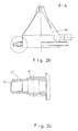
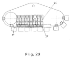
- FIGS. 2a, 2b, 2c and 2d A further embodiment of the crawler vehicle is shown in FIGS. 2a, 2b, 2c and 2d.
- the caterpillars 10 ' are fastened to the load carrying frame 12' by means of quick connections 11 '.
- the turntable 14 ' is fastened to the load carrying frame 12', in which the guide rollers 15 'are guided, as shown enlarged in FIG. 2c.
- the permanent electromagnets in this embodiment are designed as polarizable electromagnets.
- polarizable electromagnets the use of suitable permanent magnet materials maintains the magnetic flux even after the excitation current has been switched off, after the excitation current has previously sufficiently polarized the permanent magnet material. With an excitation current, both the permanent magnet material in the neutral state can be polarized and (by an opposite excitation current) the polarized permanent magnet material can be neutralized again.
- the front holding magnet When driving, the front holding magnet is magnetized by means of a sliding contact (not shown) after it comes into contact with the processing surface.
- the rear holding magnet is demagnetized from the magnetic surface by means of a further sliding contact before it is tipped over.
- the adhesive force generated by the magnetic magnets on the magnetic surface is sufficient to support the weight of the crawler vehicle and the tool to be picked up.
- the neutralization of the holding magnets is achieved by a short-term excitation current induced via sliding contacts.
- the turning process proceeds as described in the first embodiment.
- the holding magnets are magnetized again by a further excitation current.
- the caterpillar drives are controllable so that they can change direction.
- the crawler belt is flexibly mounted.
- This storage for caterpillar tracks is generally used for caterpillar vehicles with a caterpillar track 19.
- the chain links are guided over guide rollers 27 during contact with the surface.
- the guide rollers 27 are arranged on spring elements 26.
- the spring elements 26 can expand and compress so that they can adapt to unevenness in the surface.
- the jet bell 40 is a conical construction made of light metal or plastic.
- the jet bell 40 arranged on the load support frame is used perpendicular to the processed surface.
- the jet bell 40 is sealed off from the machined surface with all-round plastic bristles 42.
- the passage 52 for the blasting hose 43 is provided at the tip of the blasting bell 40.
- the blasting hose 43 is inserted into the blasting bell 40 for approximately 500 mm to 1,000 mm.
- At the tip of the blasting hose 43 there is a blasting nozzle 45 through which the blasting material 44 supplied under pressure is applied to the processing surface 49.
- the blasting material 44 as well as the coating or dirt detached from the surface are conducted to a disposal and cleaning unit via the suction nozzle 51 attached to the side of the jet bell 40 and the suction hose 41 connected to it.
- the supply lines for the caterpillar vehicle and the blasting device are guided on a fastening bracket (not shown).
- This mounting bracket is equipped with a measuring system that monitors the tension of the supply lines. If the tension of the supply lines exceeds a defined tolerance range, the caterpillar drive is stopped immediately and the operator is informed accordingly.
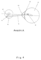
- FIG. 4 shows the eccentric drive of the blasting device from the bottom view.
- the jet bell 40 there is a passage 62 through which the rod 66 is guided.
- the implementation 62 is with bast or plastic bristles sealed to prevent the blasting material from escaping.
- the rod 66 is mounted on a bearing 63 which is attached to the jet bell 40.
- the jet nozzle 45 is attached to one end of the rod 66.
- the other end of the rod 66 is connected to an eccentric disk 61 by a fastening element 65.
- the size of the machining surface over which the jet nozzle rotates is set via the elongated hole 67 in the eccentric disk 61.
- the eccentric disk 61 is driven by an electric motor, not shown.
Landscapes
- Engineering & Computer Science (AREA)
- Chemical & Material Sciences (AREA)
- Combustion & Propulsion (AREA)
- Mechanical Engineering (AREA)
- Ocean & Marine Engineering (AREA)
- Transportation (AREA)
- Manipulator (AREA)
- Cleaning In General (AREA)
Applications Claiming Priority (2)
| Application Number | Priority Date | Filing Date | Title |
|---|---|---|---|
| DE4445055 | 1994-12-07 | ||
| DE19944445055 DE4445055A1 (de) | 1994-12-07 | 1994-12-07 | Verfahren und Raupenfahrzeug zum Befahren magnetischer Oberflächen |
Publications (2)
| Publication Number | Publication Date |
|---|---|
| EP0716006A2 true EP0716006A2 (fr) | 1996-06-12 |
| EP0716006A3 EP0716006A3 (fr) | 1997-10-01 |
Family
ID=6536110
Family Applications (1)
| Application Number | Title | Priority Date | Filing Date |
|---|---|---|---|
| EP95250299A Withdrawn EP0716006A3 (fr) | 1994-12-07 | 1995-12-06 | Méthode et véhicule à chenilles pour circuler sur une surface magnétique |
Country Status (2)
| Country | Link |
|---|---|
| EP (1) | EP0716006A3 (fr) |
| DE (1) | DE4445055A1 (fr) |
Cited By (11)
| Publication number | Priority date | Publication date | Assignee | Title |
|---|---|---|---|---|
| WO1999007489A1 (fr) * | 1997-08-07 | 1999-02-18 | Broadbent's, Inc. | Unite mobile commandee a distance servant a distribuer un liquide sous pression |
| ES2276631A1 (es) * | 2005-12-15 | 2007-06-16 | Ascend Rmm, S.L. | Robor trepador limpiador deslizante por cadena de electroimanes. |
| DE102009047992B3 (de) * | 2009-10-01 | 2011-03-17 | Niederberger Patent Ag | Kletterroboter für das Befahren von Haftoberflächen |
| DE102009047991B3 (de) * | 2009-10-01 | 2011-03-31 | Niederberger Patent Ag | Kletterroboter für das Befahren von Haftoberflächen |
| WO2014185791A1 (fr) * | 2013-05-16 | 2014-11-20 | Høgskolen I Ålesund | Véhicule immergé |
| US9533724B2 (en) | 2015-02-17 | 2017-01-03 | The Boeing Company | Electro-permanent magnetic attachment of a vehicle to an object |
| WO2017085678A1 (fr) * | 2015-11-18 | 2017-05-26 | Adroc Tech S.R.O. | Courroie de traction de véhicule |
| CN110328653A (zh) * | 2019-07-19 | 2019-10-15 | 国网电力科学研究院武汉南瑞有限责任公司 | 一种轨道式巡检机器人行走机构 |
| WO2020063759A1 (fr) * | 2018-09-30 | 2020-04-02 | 友联船厂(蛇口)有限公司 | Structure de circuit magnétique pour chenille à aimant permanent de robot grimpant |
| WO2021144418A1 (fr) * | 2020-01-17 | 2021-07-22 | MagneCat UG (haftungsbeschränkt) | Véhicule à chenilles entraîné par un moteur linéaire |
| CN119467998A (zh) * | 2024-12-24 | 2025-02-18 | 中国长江三峡集团有限公司 | 用于闸门除锈机升降机的行走装置及其使用方法 |
Families Citing this family (2)
| Publication number | Priority date | Publication date | Assignee | Title |
|---|---|---|---|---|
| DE20208687U1 (de) | 2002-03-26 | 2002-09-05 | falch hochdruckstrahlsysteme gmbh, 89188 Merklingen | Hochdruckreinigungsgerät für im wesentlichen ebene Flächen |
| CN103523105B (zh) * | 2013-10-28 | 2016-03-16 | 常州工学院 | 一种用于爬壁机器人的履带吸盘组合式行走装置 |
Citations (2)
| Publication number | Priority date | Publication date | Assignee | Title |
|---|---|---|---|---|
| DE2023683A1 (de) | 1969-05-16 | 1970-12-03 | Hitachi Metals Ltd | OI.Q8.69 " 60410-69 Magnetfahrzeug |
| DE2413688A1 (de) | 1973-03-21 | 1974-10-24 | Universal Crawler Co Ltd | Kletterfahrzeug |
Family Cites Families (4)
| Publication number | Priority date | Publication date | Assignee | Title |
|---|---|---|---|---|
| DE106336C (fr) * | ||||
| CH330357A (de) * | 1953-08-17 | 1958-05-31 | Baermann Max | Verfahren und Vorrichtung zur Erhöhung der Schienenhaftung von Gleisförderern, insbesondere Lokomotiven |
| DD277244B5 (de) * | 1988-11-25 | 1996-04-18 | Kvaerner Warnow Werft Gmbh | Verfahren und Einrichtung zum Betreiben eines mobilen Geraetetraegers mit Gleisketten aus dauermagnetischen Haftsystemen |
| US5363935A (en) * | 1993-05-14 | 1994-11-15 | Carnegie Mellon University | Reconfigurable mobile vehicle with magnetic tracks |
-
1994
- 1994-12-07 DE DE19944445055 patent/DE4445055A1/de not_active Ceased
-
1995
- 1995-12-06 EP EP95250299A patent/EP0716006A3/fr not_active Withdrawn
Patent Citations (2)
| Publication number | Priority date | Publication date | Assignee | Title |
|---|---|---|---|---|
| DE2023683A1 (de) | 1969-05-16 | 1970-12-03 | Hitachi Metals Ltd | OI.Q8.69 " 60410-69 Magnetfahrzeug |
| DE2413688A1 (de) | 1973-03-21 | 1974-10-24 | Universal Crawler Co Ltd | Kletterfahrzeug |
Cited By (16)
| Publication number | Priority date | Publication date | Assignee | Title |
|---|---|---|---|---|
| WO1999007489A1 (fr) * | 1997-08-07 | 1999-02-18 | Broadbent's, Inc. | Unite mobile commandee a distance servant a distribuer un liquide sous pression |
| ES2276631A1 (es) * | 2005-12-15 | 2007-06-16 | Ascend Rmm, S.L. | Robor trepador limpiador deslizante por cadena de electroimanes. |
| ES2276631B1 (es) * | 2005-12-15 | 2008-06-16 | Ascend Rmm, S.L. | Robot trepador limpiador deslizante por cadena de electroimanes. |
| DE102009047992B3 (de) * | 2009-10-01 | 2011-03-17 | Niederberger Patent Ag | Kletterroboter für das Befahren von Haftoberflächen |
| DE102009047991B3 (de) * | 2009-10-01 | 2011-03-31 | Niederberger Patent Ag | Kletterroboter für das Befahren von Haftoberflächen |
| WO2011038870A1 (fr) | 2009-10-01 | 2011-04-07 | Niederberger Patent Ag | Robot grimpant destiné à se déplacer sur des surfaces à adhérence |
| WO2011038871A1 (fr) | 2009-10-01 | 2011-04-07 | Niederberger Patent Ag | Robot grimpeur destiné au déplacement sur des surfaces d'adhérence |
| WO2014185791A1 (fr) * | 2013-05-16 | 2014-11-20 | Høgskolen I Ålesund | Véhicule immergé |
| US9533724B2 (en) | 2015-02-17 | 2017-01-03 | The Boeing Company | Electro-permanent magnetic attachment of a vehicle to an object |
| WO2017085678A1 (fr) * | 2015-11-18 | 2017-05-26 | Adroc Tech S.R.O. | Courroie de traction de véhicule |
| WO2020063759A1 (fr) * | 2018-09-30 | 2020-04-02 | 友联船厂(蛇口)有限公司 | Structure de circuit magnétique pour chenille à aimant permanent de robot grimpant |
| CN110328653A (zh) * | 2019-07-19 | 2019-10-15 | 国网电力科学研究院武汉南瑞有限责任公司 | 一种轨道式巡检机器人行走机构 |
| WO2021144418A1 (fr) * | 2020-01-17 | 2021-07-22 | MagneCat UG (haftungsbeschränkt) | Véhicule à chenilles entraîné par un moteur linéaire |
| CN114981195A (zh) * | 2020-01-17 | 2022-08-30 | 磁履有限责任公司 | 线性马达驱动的履带式运输工具 |
| CN114981195B (zh) * | 2020-01-17 | 2024-03-29 | 磁履有限责任公司 | 线性马达驱动的履带式运输工具 |
| CN119467998A (zh) * | 2024-12-24 | 2025-02-18 | 中国长江三峡集团有限公司 | 用于闸门除锈机升降机的行走装置及其使用方法 |
Also Published As
| Publication number | Publication date |
|---|---|
| EP0716006A3 (fr) | 1997-10-01 |
| DE4445055A1 (de) | 1996-06-13 |
Similar Documents
| Publication | Publication Date | Title |
|---|---|---|
| DE2023683C3 (de) | Fahrzeug mit magnetischer Boden härtung | |
| DE69526122T2 (de) | Magnetische fahreinrichtung vom typ gleiskette | |
| EP0716006A2 (fr) | Méthode et véhicule à chenilles pour circuler sur une surface magnétique | |
| EP1132321B1 (fr) | Transporteur à rouleaux | |
| EP0273135B1 (fr) | Procédé et installation pour l'orientation et le déplacement longitudinal de corps arrondis de boîte relativement à un appareil de soudage | |
| DE112010004879T5 (de) | System und Verfahren zum Sammeln von Bahnschienenschwellenplatten aus einem Schienenbett | |
| DE3440250A1 (de) | Vorrichtung zur beschichtung der innenflaeche von roehren | |
| DE2934752C2 (de) | Vorrichtung zum Überführen einer Luftreifen-Lauffläche auf eine Aufbautrommel und zum Abnehmen des Reifenrohlings von der Aufbautrommel zu dessen Überführung auf eine Fördereinrichtung | |
| DE3121218C2 (fr) | ||
| DE4210188C2 (de) | Transportanlage zur Förderung von Gütern entlang einer vorgegebenen Förderlinie | |
| WO2000035734A1 (fr) | Chariot de manutention | |
| EP0949173A2 (fr) | Appareil et procédé pour le changement automatique de rouleaux de film | |
| DE102017210160A1 (de) | Transporteinrichtung, Transportsystem und Verfahren zum Transport von Gegenständen | |
| DE3225595A1 (de) | Transportbahn | |
| EP0493527B1 (fr) | Procede et dispositif pour aligner et traiter conjointement des nappes de pieces molles | |
| DE69814569T2 (de) | Vorrichtung zur Absaugung und Sammlung der Abgase eines Fahrzeuges | |
| DE2413688A1 (de) | Kletterfahrzeug | |
| DE3806347A1 (de) | Transportsystem | |
| DE69109272T2 (de) | Verfahren und vorrichtung zum bearbeiten eines kerns. | |
| DE3402054C2 (de) | Maschine zum Abschleifen der Innenseiten zweier unter einem Winkel zueinander stehender Flächen | |
| DE60005455T2 (de) | Rakelgerät | |
| EP0985614A2 (fr) | Dispositif pour transporter un matériau en forme de plaque | |
| DE19644476A1 (de) | Einstellbare Transportvorrichtung | |
| DE4411213C2 (de) | Druckmaschine | |
| DE875023C (de) | Transportvorrichtung fuer Walzwerkserzeugnisse |
Legal Events
| Date | Code | Title | Description |
|---|---|---|---|
| PUAI | Public reference made under article 153(3) epc to a published international application that has entered the european phase |
Free format text: ORIGINAL CODE: 0009012 |
|
| AK | Designated contracting states |
Kind code of ref document: A2 Designated state(s): AT BE CH DE DK ES FR GB GR IE IT LI NL PT SE |
|
| PUAL | Search report despatched |
Free format text: ORIGINAL CODE: 0009013 |
|
| AK | Designated contracting states |
Kind code of ref document: A3 Designated state(s): AT BE CH DE DK ES FR GB GR IE IT LI NL PT SE |
|
| STAA | Information on the status of an ep patent application or granted ep patent |
Free format text: STATUS: THE APPLICATION IS DEEMED TO BE WITHDRAWN |
|
| 18D | Application deemed to be withdrawn |
Effective date: 19980402 |