EP0716177B1 - Wäschetrommel einer Waschmaschine - Google Patents
Wäschetrommel einer Waschmaschine Download PDFInfo
- Publication number
- EP0716177B1 EP0716177B1 EP95308863A EP95308863A EP0716177B1 EP 0716177 B1 EP0716177 B1 EP 0716177B1 EP 95308863 A EP95308863 A EP 95308863A EP 95308863 A EP95308863 A EP 95308863A EP 0716177 B1 EP0716177 B1 EP 0716177B1
- Authority
- EP
- European Patent Office
- Prior art keywords
- washing machine
- fluid
- laundry tub
- tub
- drum washing
- Prior art date
- Legal status (The legal status is an assumption and is not a legal conclusion. Google has not performed a legal analysis and makes no representation as to the accuracy of the status listed.)
- Expired - Lifetime
Links
Images




Classifications
-
- D—TEXTILES; PAPER
- D06—TREATMENT OF TEXTILES OR THE LIKE; LAUNDERING; FLEXIBLE MATERIALS NOT OTHERWISE PROVIDED FOR
- D06F—LAUNDERING, DRYING, IRONING, PRESSING OR FOLDING TEXTILE ARTICLES
- D06F37/00—Details specific to washing machines covered by groups D06F21/00 - D06F25/00
- D06F37/20—Mountings, e.g. resilient mountings, for the rotary receptacle, motor, tub or casing; Preventing or damping vibrations
- D06F37/22—Mountings, e.g. resilient mountings, for the rotary receptacle, motor, tub or casing; Preventing or damping vibrations in machines with a receptacle rotating or oscillating about a horizontal axis
- D06F37/225—Damping vibrations by displacing, supplying or ejecting a material, e.g. liquid, into or from counterbalancing pockets
-
- D—TEXTILES; PAPER
- D06—TREATMENT OF TEXTILES OR THE LIKE; LAUNDERING; FLEXIBLE MATERIALS NOT OTHERWISE PROVIDED FOR
- D06F—LAUNDERING, DRYING, IRONING, PRESSING OR FOLDING TEXTILE ARTICLES
- D06F37/00—Details specific to washing machines covered by groups D06F21/00 - D06F25/00
- D06F37/02—Rotary receptacles, e.g. drums
- D06F37/04—Rotary receptacles, e.g. drums adapted for rotation or oscillation about a horizontal or inclined axis
-
- D—TEXTILES; PAPER
- D06—TREATMENT OF TEXTILES OR THE LIKE; LAUNDERING; FLEXIBLE MATERIALS NOT OTHERWISE PROVIDED FOR
- D06F—LAUNDERING, DRYING, IRONING, PRESSING OR FOLDING TEXTILE ARTICLES
- D06F37/00—Details specific to washing machines covered by groups D06F21/00 - D06F25/00
- D06F37/26—Casings; Tubs
- D06F37/265—Counterweights mounted to the tub; Mountings therefor
-
- F—MECHANICAL ENGINEERING; LIGHTING; HEATING; WEAPONS; BLASTING
- F16—ENGINEERING ELEMENTS AND UNITS; GENERAL MEASURES FOR PRODUCING AND MAINTAINING EFFECTIVE FUNCTIONING OF MACHINES OR INSTALLATIONS; THERMAL INSULATION IN GENERAL
- F16F—SPRINGS; SHOCK-ABSORBERS; MEANS FOR DAMPING VIBRATION
- F16F15/00—Suppression of vibrations in systems; Means or arrangements for avoiding or reducing out-of-balance forces, e.g. due to motion
- F16F15/10—Suppression of vibrations in rotating systems by making use of members moving with the system
- F16F15/16—Suppression of vibrations in rotating systems by making use of members moving with the system using a fluid or pasty material
-
- Y—GENERAL TAGGING OF NEW TECHNOLOGICAL DEVELOPMENTS; GENERAL TAGGING OF CROSS-SECTIONAL TECHNOLOGIES SPANNING OVER SEVERAL SECTIONS OF THE IPC; TECHNICAL SUBJECTS COVERED BY FORMER USPC CROSS-REFERENCE ART COLLECTIONS [XRACs] AND DIGESTS
- Y10—TECHNICAL SUBJECTS COVERED BY FORMER USPC
- Y10T—TECHNICAL SUBJECTS COVERED BY FORMER US CLASSIFICATION
- Y10T74/00—Machine element or mechanism
- Y10T74/21—Elements
- Y10T74/2109—Balancing for drum, e.g., washing machine or arm-type structure, etc., centrifuge, etc.
Definitions
- the invention relates to a laundry tub of a drum washing machine, and in particular, to providing a laundry tub of a conical shape including a fluid balancer.
- Prior art drum washing machines are used to wash or dehydrate laundry or clothes in a manner that a laundry tub coupled to a horizontal rotating shaft pulls laundry up and then drops it down by centripetal force. This means that laundry is gathered at the random places on which its weight is exerted, resulting in an unbalanced state of the laundry tub. So, a stress concentration occurs on the horizontal rotating shaft following by the addition of fatigue thereto. Further, the unbalanced state prevailing during the dehydrating causes the rotating shaft to be subject to overload, thereby producing vibration. In order to solve these problems, there has been developed a balancer surrounding the washing machine.
- a conventional drum washing machine is shown, provided with a balancer, which comprises an outer tub 2 supported in a housing 1 and a laundry tub 6 fixed at one end of a horizontal rotating shaft 4 which is mounted on the rear portion of the outer tub 2, in which the laundry tub 6 is formed so that a rear portion coupled to the horizontal rotating shaft 4 has a diameter larger than a front portion adjacent to an opening 110.
- the laundry tub 6 can be used in washing, dehydrating and rinsing operations, and is thus adaptable to a full automatic washing machine.
- the housing 1 includes a door 10 openably and closedly mounted on the front portion to throw in and remove laundry items 8.
- the outer tub 2 stores washing water supplied by means of a feeding device (not shown) in a space containing the drum washing tub 6. Also, weight balancers 12, 14 and 16 are respectively disposed on the upper and front surfaces of the outer tub 2.
- a shock absorber 18 is mounted on the housing 1 to support the outer tub 2.
- a motor 20 is attached on the bottom surface of the outer tub 2 to rotate the laundry tub 6 at the different speeds required for the washing operation and the dehydrating operation.
- the motor 20 includes a rotating shaft 22 to one end of which a pulley 24 is fixed.
- the horizontal rotating shaft 4 includes a pulley 28 mounted at the one end of the shaft to be rotated by means of a belt 26 connected to the pulley 24.
- the horizontal rotating shaft 4 also is supported on a bearing structure 30 for ease of rotation.
- a supporting member 32 is mounted on the rear portion of the outer tub 2 to support the horizontal rotating shaft 4.
- a drain device 34 is mounted on the bottom surface of the outer tub 2 to discharge water according to the opening/closing control of a controller (not shown).
- Spring members 36 and 38 are suspended between the upper surface of the outer tub 2 and the housing 1, and a shock absorbing supporter 40 is mounted on the inner portion of the housing 1 to keep a suitable clearance between the housing 1 and the outer tub 2.
- the outer tub 2 is elastically supported in the housing 1 by means of springs 38 and 39 and the shock absorber 18.
- the drum washing machine uses a solid balancer including a heavier mass, so that it can not actively act against the changing of a load. Also, overload happens due to the centrifugal force during the high speed rotation of the laundry tub and is transferred to the supporting member for the horizontal rotating shaft. At that time, it causes the horizontal rotating shaft to be stressed, resulting in inducing vibration of the washing machine while generating noise. Furthermore, it deteriorates the endurance of the washing machine.
- DE 27 46 989 discloses a washing machine having a fluid balancer, in which the fluid balancer is shaped to achieve a compact configuration of the fluid balancer and a tub of the washing machine.
- an object of the invention is to provide a drum washing machine including a fluid balancer to minimize the occurrence of vibrations not only in the lower speed mode but also in the high speed mode.
- Another object of the invention is to provide a drum washing machine including a fluid balancer for responding quickly to the vibrations of each rotation mode.
- a drum washing machine comprises a housing; an outer tub suspended in the housing; a laundry tub movably mounted on a transverse axis in the housing and including a plurality of dehydrating holes; means for feeding washing water to the outer tub and the laundry tub; means for discharging water out of the housing; a driving means for transferring driving force to the transverse shaft of the laundry tub; and a fluid balancer mounted remotely from the transverse shaft on the outer periphery of the laundry tub; a fluid absorbent being placed in the fluid balancer characterised in that the fluid balancer has a height which is highest adjacent to an opening in the laundry tub and lowest at a place remote from said opening.
- the laundry tub has a structure such that one portion for mounting the fluid balancer has a diameter larger than other portion for fixing the transverse shaft.
- the fluid absorbents are arranged in a plurality of discontinuous circle shapes in the center to the horizontal rotating shaft.
- a laundry tub 100 is designed to have a conical structure that is attached to a horizontal rotating shaft 4, in which the laundry tub 100 includes a rear portion having a diameter larger than a front portion adjacent to an opening 110. It prevents laundry items 8 from being gathered near the opening 110 in the drum or laundry tub 100. Thus, it is preferable that an angle oc formed between the rear and side portions is 80°.
- a fluid balancer 102 is configured in a corresponding shape to surround the outer periphery of the laundry tub 100 from the front portion to a predetermined distance, which is coupled in a snap method or an integral structure with the laundry tub 100.
- the fluid balancer 102 is formed as a reverse-righted triangle in transverse cross-section, the height of which is highest adjacent to the opening 110, while the height is lowest at the place spaced far away from the opening 110 or adjacent to the horizontal rotating shaft 4. This reduces the centrifugal force of a biased weight of the tub, when the laundry is closely contacted to the inner surface to induce vibrations in a maximum magnitude adjacent to the opening 110 during the high speed rotation (the dehydrating operation) of the laundry tub 100.
- a fluid absorbing member 104 is disposed in the fluid balancer 102.
- the absorbing member 104 is a sponge for easily absorbing water, but may be any material having a good absorbing property.
- the absorbing member 104 is disposed in a larger amount adjacent to the opening 110 or the highest height portion. It can offset the larger magnitude of vibration induced near the free end or the opening 110 of the laundry tub 110.
- the absorbing member 104 is integrally configured as an annular ring, around the center to the horizontal rotating shaft 4, with a predetermined radius.
- the drum washing machine enables the laundry tub to be operated as follows : when the laundry tub 100 is non-operated, the fluid balancer 102 is stalled to keep fluid at the lowest portion thereof.
- the laundry tub 100 is rotated at a lower speed along with the fluid balancer 102.
- the fluid absorbing member 104 is moved outward with the absorbed fluid to a first area which is the lowest portion of the fluid balancer 102.
- a second area following the first area also absorbs fluid and moves up toward the highest portion of the fluid balancer 102. Therefore, the fluid absorbing member 104 passes through fluid to absorb the equivalent amounts. It enables the laundry tub 100 to be maintained at the uniform weight state throughout the full lengthwise thereof, thereby accomplishing the equivalent balance of the laundry tub to be rotated in a stable state.
- the laundry tub 100 also is rotated at high speed.
- fluid contained in the absorbing member 104 is drawn out by the centrifugal force and then collected toward the utmost inner periphery of the fluid balancer 102.
- the fluid balancer 102 is subject to the force applied toward the direction spaced far away from the outer wall of the laundry tub 100.
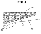
- a fluid balancer 202 is mounted on the outer periphery of the laundry tub 100.
- a plurality of partition walls 204 are longitudinally extended from the bottom surface of the fluid balancer 202 to have the same level of fluid, which are spaced away in a predetermined interval from one another.
- the fluid balancer 202 is acted in the same manner as that of Figure 3, but the more the rotation speed of the fluid balancer 202 is, the more fluid is flowed over and collected in turns from the lowest partition wall adjacent to the horizontal rotating shaft 4 toward the highest partition adjacent to the opening 110.
- the operation of the fluid balancer 202 is similar to that of a fluid balancer 102 in the first embodiment.
- a drum washing machine is a washing machine of a front loading type for throwing in and drawing out laundry through the side wall of an outer tub, but it is adaptable to a washing machine of a top loading type for throwing in and drawing out laundry through the upper portion of an outer tub as shown in Figure 5.
- the invention comprises a fluid balancer of a reverse righted triangle mounted around the outer periphery of a laundry tub in a manner that its highest portion is arranged adjacent to the opening thereof.
- the fluid balancer acts against the vibrations generated during the rotation of a laundry tub to prevent the unbalance of a load.
- annular fluid absorbent uniformly contains fluid in itself to maintain the uniform weight throughout the full lengthwise of a laundry tub, thereby leading to the stable rotation of the laundry tub.
- fluid contained in the absorbent is drawn out/moved toward the place far away from the outer wall of the laundry tub in proportion to the rotation speed, so that the unbalance relatively varied by its weight can be reduced.
Landscapes
- Engineering & Computer Science (AREA)
- Textile Engineering (AREA)
- General Engineering & Computer Science (AREA)
- Physics & Mathematics (AREA)
- Acoustics & Sound (AREA)
- Aviation & Aerospace Engineering (AREA)
- Mechanical Engineering (AREA)
- Main Body Construction Of Washing Machines And Laundry Dryers (AREA)
- Accessory Of Washing/Drying Machine, Commercial Washing/Drying Machine, Other Washing/Drying Machine (AREA)
Claims (6)
- Trommelwaschmaschine, die umfaßt:dadurch gekennzeichnet, daß die Fluid-Auswuchteinrichtung (102) eine Höhe hat, die an eine Öffnung (110) in der Wäschetrommel (100) angrenzend am größten ist und an einer von der Öffnung (110) weit beabstandeten Stelle am geringsten ist.ein Gehäuse (1);eine äußere Trommel (2), die in dem Gehäuse (1) aufgehängt ist;eine Wäschetrommel (100), die beweglich auf einer Querachse in dem Gehäuse (1) angebracht ist und eine Vielzahl von Entwässerungsöffnungen enthält;eine Einrichtung zur Zufuhr von Waschwasser zu der äußeren Trommel (2) und der Wäschetrommel (100);eine Einrichtung (34) zum Ableiten von Wasser aus dem Gehäuse; eine Antriebseinrichtung, die Antriebskraft auf die Querwelle (4) der Wäschetrommel (100) überträgt; sowieeine Fluid-Auswuchteinrichtung (102), die von der Querwelle (4) entfernt am Außenumfang der Wäschetrommel (100) angebracht ist; ein fluidabsorbierendes Element (104), das in der Fluid-Auswuchteinrichtung (102) angeordnet ist;
- Trommelwaschmaschine nach Anspruch 1, wobei:
die Wäschetrommel (100) so aufgebaut ist, daß ein Abschnitt zum Anbringen der Fluid-Auswuchteinrichtung (102) einen größeren Durchmesser hat als ein anderer Abschnitt zum Befestigen der Querwelle (4). - Trommelwaschmaschine nach Anspruch 2, wobei ein fluidabsorbierendes Element (104) in einer größeren Menge an der von der Querwelle (4) entfernten Stelle angeordnet ist.
- Trommelwaschmaschine nach Anspruch 2, wobei die Fluid-Auswuchteinrichtung (102) eine Vielzahl von Trennwänden (104) enthält, die sich in Längsrichtung von der Bodenfläche derselben aus erstrecken und miteinander in Verbindung stehen.
- Trommelwaschmaschine nach Anspruch 1, wobei das fluidabsorbierende Element (104) integral in einer Ringform in der Fluid-Auswuchteinrichtung (102) angeordnet ist, die auf die horizontale Drehwelle (4) zentriert ist.
- Trommelwaschmaschine nach Anspruch 1, wobei:
das fluidabsorbierende Element (104) integral als eine Vielzahl von Ringen ausgebildet ist, die auf der horizontalen Welle (4) zentriert sind.
Applications Claiming Priority (2)
| Application Number | Priority Date | Filing Date | Title |
|---|---|---|---|
| KR2019940033409U KR200151035Y1 (ko) | 1994-12-07 | 1994-12-07 | 드럼형 세탁기의 진동 및 소음 감소장치 |
| KR9433409U | 1994-12-07 |
Publications (2)
| Publication Number | Publication Date |
|---|---|
| EP0716177A1 EP0716177A1 (de) | 1996-06-12 |
| EP0716177B1 true EP0716177B1 (de) | 1999-01-13 |
Family
ID=19400800
Family Applications (1)
| Application Number | Title | Priority Date | Filing Date |
|---|---|---|---|
| EP95308863A Expired - Lifetime EP0716177B1 (de) | 1994-12-07 | 1995-12-06 | Wäschetrommel einer Waschmaschine |
Country Status (5)
| Country | Link |
|---|---|
| US (1) | US5709109A (de) |
| EP (1) | EP0716177B1 (de) |
| JP (1) | JP2755567B2 (de) |
| KR (1) | KR200151035Y1 (de) |
| DE (1) | DE69507274T2 (de) |
Cited By (6)
| Publication number | Priority date | Publication date | Assignee | Title |
|---|---|---|---|---|
| US7827834B2 (en) | 2005-09-30 | 2010-11-09 | Lg Electronics Inc. | Bearing housing assembly of drum-type washing machine and drum-type washing machine with the same |
| US7841220B2 (en) | 2005-09-30 | 2010-11-30 | Lg Electronics Inc. | Drum-type washing machine |
| US7930910B2 (en) | 2002-12-27 | 2011-04-26 | Lg Electronics Inc. | Drum type washing machine |
| US8087267B2 (en) | 2002-12-27 | 2012-01-03 | Lg Electronics Inc. | Drum type washing machine |
| USRE43625E1 (en) | 2006-03-29 | 2012-09-04 | Lg Electronics Inc. | Drum type washing machine |
| US8429938B2 (en) | 2004-07-20 | 2013-04-30 | Lg Electronics Inc. | Drum-type washing machine and bearing housing structure thereof |
Families Citing this family (23)
| Publication number | Priority date | Publication date | Assignee | Title |
|---|---|---|---|---|
| KR960023437A (ko) * | 1994-12-22 | 1996-07-20 | 구자홍 | 전자동 세탁기의 액체 발란스장치 |
| JPH09313766A (ja) * | 1996-01-31 | 1997-12-09 | Sharp Corp | ドラム式乾燥洗濯機、ドラム式乾燥機およびドラム式乾燥洗濯機の動作方法 |
| KR20010009545A (ko) * | 1999-07-12 | 2001-02-05 | 윤종용 | 드럼세탁기의 회전조 |
| KR20010037665A (ko) * | 1999-10-19 | 2001-05-15 | 구자홍 | 직결식 드럼세탁기의 진동저감장치 |
| US6550292B1 (en) * | 2000-04-03 | 2003-04-22 | Whirlpool Corporation | Dynamic balancer for an automatic washer |
| US6327732B1 (en) | 2000-05-10 | 2001-12-11 | Maytag Corporation | Fluid balancing ring and method for using same |
| JP2002355491A (ja) * | 2001-03-28 | 2002-12-10 | Sanyo Electric Co Ltd | 洗濯機 |
| KR101073508B1 (ko) * | 2003-11-17 | 2011-10-17 | 삼성전자주식회사 | 의류 건조기 |
| KR101133607B1 (ko) * | 2004-02-25 | 2012-04-10 | 엘지전자 주식회사 | 드럼세탁기의 댐퍼 핀 |
| KR101093878B1 (ko) * | 2004-06-05 | 2011-12-13 | 엘지전자 주식회사 | 건조기의 드럼 장치 |
| DE602004024975D1 (de) * | 2004-07-22 | 2010-02-25 | Candy Spa | Trommel für Waschmaschine, Waschtrockner, Trockner o.ä. |
| KR100640866B1 (ko) * | 2004-09-08 | 2006-11-02 | 엘지전자 주식회사 | 세탁기의 밸런서 |
| ITMI20050447A1 (it) * | 2005-03-17 | 2006-09-18 | Miglio Emilio S R L | Dispositivo per la connessione dei braccetti atti a supportare il cestello di macchine lavabiancheria e simili |
| EA014041B1 (ru) * | 2006-03-07 | 2010-08-30 | Бсх Бош Унд Сименс Хаусгерете Гмбх | Контейнер бытового прибора для стирального или моющего раствора и бытовой прибор с таким контейнером |
| JP2008220829A (ja) * | 2007-03-15 | 2008-09-25 | Sharp Corp | ドラム式洗濯機 |
| RU2516908C2 (ru) * | 2008-09-10 | 2014-05-20 | КАРНЕХАММАР, Ларс Бертил | Способ, система и устройство для уменьшения вибрации в машине для обработки предметов, такой как стиральная машина |
| EP2519672A1 (de) * | 2009-12-31 | 2012-11-07 | Arçelik Anonim Sirketi | Waschmaschine mit ausgeglichener asymmetrischer last |
| WO2015176536A1 (zh) * | 2014-05-19 | 2015-11-26 | 海尔亚洲国际株式会社 | 洗衣机 |
| WO2016138924A1 (en) * | 2015-03-02 | 2016-09-09 | Arcelik Anonim Sirketi | A laundry machine with an improved fluid distribution load balance system |
| CN105568609A (zh) * | 2015-12-18 | 2016-05-11 | 南京乐金熊猫电器有限公司 | 一种用于波轮洗衣机脱水时减轻振动的方法 |
| CN111286925B (zh) * | 2018-12-10 | 2022-05-31 | 无锡小天鹅电器有限公司 | 衣物处理设备、用于衣物处理设备的平衡环 |
| CN111394927B (zh) * | 2019-01-02 | 2023-02-17 | 青岛海尔洗涤电器有限公司 | 一种滚筒洗衣机及其控制方法 |
| GB2592265B (en) * | 2020-02-24 | 2024-01-10 | Ebac Ltd | Laundry appliance with self-balancing drum assembly |
Family Cites Families (8)
| Publication number | Priority date | Publication date | Assignee | Title |
|---|---|---|---|---|
| US2647386A (en) * | 1948-04-03 | 1953-08-04 | Easy Washing Machine Corp | Washing machine |
| US2645107A (en) * | 1948-12-20 | 1953-07-14 | Maytag Co | Combined washing machine and centrifugal extractor |
| JPS5351671A (en) * | 1976-10-20 | 1978-05-11 | Hitachi Ltd | Drum type washing machine |
| JPH0696069B2 (ja) | 1989-03-28 | 1994-11-30 | 三洋電機株式会社 | 洗濯機 |
| AU632439B2 (en) * | 1989-10-05 | 1992-12-24 | Sanyo Electric Co., Ltd. | Drum-type washing machine |
| JPH04150898A (ja) * | 1990-10-12 | 1992-05-25 | Kyushu Electric Power Co Inc | ドラム式洗濯機 |
| JPH067590A (ja) * | 1992-06-29 | 1994-01-18 | Matsushita Electric Ind Co Ltd | ドラム式洗濯機 |
| JPH06246092A (ja) * | 1993-02-24 | 1994-09-06 | Mitsubishi Heavy Ind Ltd | ドラム式洗濯機 |
-
1994
- 1994-12-07 KR KR2019940033409U patent/KR200151035Y1/ko not_active Expired - Fee Related
-
1995
- 1995-12-06 DE DE69507274T patent/DE69507274T2/de not_active Expired - Fee Related
- 1995-12-06 EP EP95308863A patent/EP0716177B1/de not_active Expired - Lifetime
- 1995-12-07 JP JP7319114A patent/JP2755567B2/ja not_active Expired - Fee Related
- 1995-12-07 US US08/568,698 patent/US5709109A/en not_active Expired - Fee Related
Cited By (33)
| Publication number | Priority date | Publication date | Assignee | Title |
|---|---|---|---|---|
| US8387421B2 (en) | 2002-12-27 | 2013-03-05 | Lg Electronics Inc. | Drum-type washing machine |
| US8887537B2 (en) | 2002-12-27 | 2014-11-18 | Lg Electronics Inc. | Drum-type washing machine |
| US7930910B2 (en) | 2002-12-27 | 2011-04-26 | Lg Electronics Inc. | Drum type washing machine |
| US8087267B2 (en) | 2002-12-27 | 2012-01-03 | Lg Electronics Inc. | Drum type washing machine |
| US8156770B2 (en) | 2002-12-27 | 2012-04-17 | Lg Electronics, Inc. | Drum type washing machine |
| US8671719B2 (en) | 2002-12-27 | 2014-03-18 | Lg Electronics Inc. | Drum type washing machine |
| US8646293B2 (en) | 2002-12-27 | 2014-02-11 | Lg Electronics Inc. | Drum type washing machine |
| US8646292B2 (en) | 2002-12-27 | 2014-02-11 | Lg Electronics Inc. | Drum type washing machine |
| US8616027B2 (en) | 2002-12-27 | 2013-12-31 | Lg Electronics Inc. | Drum type washing machine |
| US8302434B2 (en) | 2002-12-27 | 2012-11-06 | Lg Electronics Inc. | Drum-type washing machine |
| US8322170B2 (en) | 2002-12-27 | 2012-12-04 | Lg Electronics Inc. | Drum-type washing machine |
| US8336340B2 (en) | 2002-12-27 | 2012-12-25 | Lg Electronics Inc. | Drum-type washing machine |
| US8336339B2 (en) | 2002-12-27 | 2012-12-25 | Lg Electronics Inc. | Drum type washing machine |
| US8341983B2 (en) | 2002-12-27 | 2013-01-01 | Lg Electronics Inc. | Drum-type washing machine |
| US8429938B2 (en) | 2004-07-20 | 2013-04-30 | Lg Electronics Inc. | Drum-type washing machine and bearing housing structure thereof |
| US8800326B2 (en) | 2004-07-20 | 2014-08-12 | Lg Electronics Inc. | Drum-type washing machine and bearing housing structure thereof |
| US8726702B2 (en) | 2004-07-20 | 2014-05-20 | Lg Electronics Inc. | Drum-type washing machine and bearing housing structure thereof |
| US8434334B2 (en) | 2004-07-20 | 2013-05-07 | Lg Electronics Inc. | Drum-type washing machine and bearing housing structure thereof |
| US8931312B2 (en) | 2004-07-20 | 2015-01-13 | Lg Electronics Inc. | Drum-type washing machine and bearing housing structure thereof |
| US8677787B2 (en) | 2004-07-20 | 2014-03-25 | Lg Electronics Inc. | Drum-type washing machine and bearing housing structure thereof |
| US8887538B2 (en) | 2004-07-20 | 2014-11-18 | Lg Electronics Inc. | Drum-type washing machine and bearing housing structure thereof |
| US8783072B2 (en) | 2004-07-20 | 2014-07-22 | Lg Electronics Inc. | Drum-type washing machine and bearing housing structure thereof |
| US8234890B2 (en) | 2005-09-30 | 2012-08-07 | Lg Electronics Inc. | Drum-type washing machine |
| US8225628B2 (en) | 2005-09-30 | 2012-07-24 | Lg Electronics Inc. | Drum-type washing machine |
| US8220294B2 (en) | 2005-09-30 | 2012-07-17 | Lg Electronics Inc. | Drum-type washing machine |
| US8671718B2 (en) | 2005-09-30 | 2014-03-18 | Lg Electronics Inc. | Drum-type washing machine |
| US7841220B2 (en) | 2005-09-30 | 2010-11-30 | Lg Electronics Inc. | Drum-type washing machine |
| US7827834B2 (en) | 2005-09-30 | 2010-11-09 | Lg Electronics Inc. | Bearing housing assembly of drum-type washing machine and drum-type washing machine with the same |
| USRE43625E1 (en) | 2006-03-29 | 2012-09-04 | Lg Electronics Inc. | Drum type washing machine |
| USRE44795E1 (en) | 2006-03-29 | 2014-03-11 | Lg Electronics Inc. | Drum type washing machine |
| USRE44674E1 (en) | 2006-03-29 | 2013-12-31 | Lg Electronics Inc. | Drum type washing machine |
| USRE44028E1 (en) | 2006-03-29 | 2013-02-26 | Lg Electronics Inc. | Drum type washing machine |
| USRE44511E1 (en) | 2006-03-29 | 2013-10-01 | Lg Electronics Inc. | Drum type washing machine |
Also Published As
| Publication number | Publication date |
|---|---|
| US5709109A (en) | 1998-01-20 |
| DE69507274T2 (de) | 1999-07-08 |
| KR960022741U (ko) | 1996-07-20 |
| EP0716177A1 (de) | 1996-06-12 |
| KR200151035Y1 (ko) | 1999-07-15 |
| JPH08215473A (ja) | 1996-08-27 |
| JP2755567B2 (ja) | 1998-05-20 |
| DE69507274D1 (de) | 1999-02-25 |
Similar Documents
| Publication | Publication Date | Title |
|---|---|---|
| EP0716177B1 (de) | Wäschetrommel einer Waschmaschine | |
| EP0811717B1 (de) | Waschmachine mit Kugelvorrichtung zum Ausbalancieren | |
| EP0808934A2 (de) | Waschmaschine | |
| EP1396570B1 (de) | Verfahren zum schwingungsreduzierten Betrieb einer Trommelwasch- und trockenmaschine | |
| EP0781882B2 (de) | Trommelmaschine mit Auswuchtvorrichtungen | |
| EP0810317A1 (de) | Waschmaschine | |
| EP2573249B1 (de) | Trommelwaschmaschine | |
| EP0808932B1 (de) | Waschmaschine | |
| US5746069A (en) | Clothes washing machine having upper and lower dynamic balancers | |
| JPH0956965A (ja) | ドラム洗濯機の振動減衰装置 | |
| EP0810389A1 (de) | Auswuchteinrichtung | |
| EP0810318B1 (de) | Waschmaschine | |
| EP0806515B1 (de) | Waschmaschine | |
| EP0810319B1 (de) | Waschmaschine | |
| EP0811716A2 (de) | Waschmaschine | |
| US4007612A (en) | Washing machine balance and suspension system | |
| KR20000002191A (ko) | 드럼세탁기의 진동 방지장치 | |
| KR100360227B1 (ko) | 세탁기의 액체 밸런서 | |
| KR20050110072A (ko) | 밸런서가 구비된 드럼세탁기 및 모터 | |
| KR0136042Y1 (ko) | 드럼세탁기의 밸런싱장치 | |
| JPH09253385A (ja) | ドラム式洗濯機 | |
| JPH06246092A (ja) | ドラム式洗濯機 | |
| KR200145370Y1 (ko) | 드럼세탁기의 밸런싱장치 | |
| KR0172681B1 (ko) | 세탁기의 가변형 진동감쇠장치 | |
| KR0136039Y1 (ko) | 드럼세탁기의 밸런싱장치 |
Legal Events
| Date | Code | Title | Description |
|---|---|---|---|
| PUAI | Public reference made under article 153(3) epc to a published international application that has entered the european phase |
Free format text: ORIGINAL CODE: 0009012 |
|
| 17P | Request for examination filed |
Effective date: 19951218 |
|
| AK | Designated contracting states |
Kind code of ref document: A1 Designated state(s): DE FR GB |
|
| 17Q | First examination report despatched |
Effective date: 19970625 |
|
| GRAG | Despatch of communication of intention to grant |
Free format text: ORIGINAL CODE: EPIDOS AGRA |
|
| GRAG | Despatch of communication of intention to grant |
Free format text: ORIGINAL CODE: EPIDOS AGRA |
|
| GRAG | Despatch of communication of intention to grant |
Free format text: ORIGINAL CODE: EPIDOS AGRA |
|
| GRAH | Despatch of communication of intention to grant a patent |
Free format text: ORIGINAL CODE: EPIDOS IGRA |
|
| GRAH | Despatch of communication of intention to grant a patent |
Free format text: ORIGINAL CODE: EPIDOS IGRA |
|
| GRAA | (expected) grant |
Free format text: ORIGINAL CODE: 0009210 |
|
| AK | Designated contracting states |
Kind code of ref document: B1 Designated state(s): DE FR GB |
|
| REF | Corresponds to: |
Ref document number: 69507274 Country of ref document: DE Date of ref document: 19990225 |
|
| ET | Fr: translation filed | ||
| PLBE | No opposition filed within time limit |
Free format text: ORIGINAL CODE: 0009261 |
|
| STAA | Information on the status of an ep patent application or granted ep patent |
Free format text: STATUS: NO OPPOSITION FILED WITHIN TIME LIMIT |
|
| 26N | No opposition filed | ||
| PGFP | Annual fee paid to national office [announced via postgrant information from national office to epo] |
Ref country code: GB Payment date: 20011205 Year of fee payment: 7 |
|
| PGFP | Annual fee paid to national office [announced via postgrant information from national office to epo] |
Ref country code: FR Payment date: 20011212 Year of fee payment: 7 |
|
| REG | Reference to a national code |
Ref country code: GB Ref legal event code: IF02 |
|
| PG25 | Lapsed in a contracting state [announced via postgrant information from national office to epo] |
Ref country code: GB Free format text: LAPSE BECAUSE OF NON-PAYMENT OF DUE FEES Effective date: 20021206 |
|
| GBPC | Gb: european patent ceased through non-payment of renewal fee | ||
| PG25 | Lapsed in a contracting state [announced via postgrant information from national office to epo] |
Ref country code: FR Free format text: LAPSE BECAUSE OF NON-PAYMENT OF DUE FEES Effective date: 20030901 |
|
| REG | Reference to a national code |
Ref country code: FR Ref legal event code: ST |
|
| PGFP | Annual fee paid to national office [announced via postgrant information from national office to epo] |
Ref country code: DE Payment date: 20081205 Year of fee payment: 14 |
|
| PG25 | Lapsed in a contracting state [announced via postgrant information from national office to epo] |
Ref country code: DE Free format text: LAPSE BECAUSE OF NON-PAYMENT OF DUE FEES Effective date: 20100701 |