EP0716228A1 - Compresseur à piston à déplacement variable - Google Patents
Compresseur à piston à déplacement variable Download PDFInfo
- Publication number
- EP0716228A1 EP0716228A1 EP95119209A EP95119209A EP0716228A1 EP 0716228 A1 EP0716228 A1 EP 0716228A1 EP 95119209 A EP95119209 A EP 95119209A EP 95119209 A EP95119209 A EP 95119209A EP 0716228 A1 EP0716228 A1 EP 0716228A1
- Authority
- EP
- European Patent Office
- Prior art keywords
- swash plate
- compressor
- passage
- gas
- chamber
- Prior art date
- Legal status (The legal status is an assumption and is not a legal conclusion. Google has not performed a legal analysis and makes no representation as to the accuracy of the status listed.)
- Granted
Links
- 238000006073 displacement reaction Methods 0.000 title claims description 20
- 230000033001 locomotion Effects 0.000 claims abstract description 14
- 230000002401 inhibitory effect Effects 0.000 claims abstract description 5
- 238000001816 cooling Methods 0.000 claims description 13
- 230000004044 response Effects 0.000 claims description 5
- 238000007599 discharging Methods 0.000 claims description 2
- 239000000314 lubricant Substances 0.000 claims 4
- 230000001105 regulatory effect Effects 0.000 claims 3
- 230000001276 controlling effect Effects 0.000 claims 1
- 230000001050 lubricating effect Effects 0.000 claims 1
- 239000003507 refrigerant Substances 0.000 description 71
- 239000010687 lubricating oil Substances 0.000 description 31
- 238000005057 refrigeration Methods 0.000 description 23
- 239000003921 oil Substances 0.000 description 11
- 238000005461 lubrication Methods 0.000 description 10
- 230000004075 alteration Effects 0.000 description 6
- 230000000903 blocking effect Effects 0.000 description 6
- 230000009467 reduction Effects 0.000 description 6
- 230000008859 change Effects 0.000 description 4
- 230000007423 decrease Effects 0.000 description 4
- 238000001514 detection method Methods 0.000 description 4
- 230000009471 action Effects 0.000 description 3
- 230000004913 activation Effects 0.000 description 3
- 238000004891 communication Methods 0.000 description 3
- 230000035939 shock Effects 0.000 description 3
- 238000004378 air conditioning Methods 0.000 description 2
- 238000013459 approach Methods 0.000 description 2
- 238000010276 construction Methods 0.000 description 2
- 230000000694 effects Effects 0.000 description 2
- 230000002093 peripheral effect Effects 0.000 description 2
- 230000000717 retained effect Effects 0.000 description 2
- 238000000926 separation method Methods 0.000 description 2
- 230000005540 biological transmission Effects 0.000 description 1
- 238000006243 chemical reaction Methods 0.000 description 1
- 230000008602 contraction Effects 0.000 description 1
- 230000005284 excitation Effects 0.000 description 1
- 230000005281 excited state Effects 0.000 description 1
- 239000000463 material Substances 0.000 description 1
- 238000007789 sealing Methods 0.000 description 1
Images


Classifications
-
- F—MECHANICAL ENGINEERING; LIGHTING; HEATING; WEAPONS; BLASTING
- F04—POSITIVE - DISPLACEMENT MACHINES FOR LIQUIDS; PUMPS FOR LIQUIDS OR ELASTIC FLUIDS
- F04B—POSITIVE-DISPLACEMENT MACHINES FOR LIQUIDS; PUMPS
- F04B27/00—Multi-cylinder pumps specially adapted for elastic fluids and characterised by number or arrangement of cylinders
- F04B27/08—Multi-cylinder pumps specially adapted for elastic fluids and characterised by number or arrangement of cylinders having cylinders coaxial with, or parallel or inclined to, main shaft axis
- F04B27/14—Control
- F04B27/16—Control of pumps with stationary cylinders
- F04B27/18—Control of pumps with stationary cylinders by varying the relative positions of a swash plate and a cylinder block
- F04B27/1804—Controlled by crankcase pressure
-
- F—MECHANICAL ENGINEERING; LIGHTING; HEATING; WEAPONS; BLASTING
- F04—POSITIVE - DISPLACEMENT MACHINES FOR LIQUIDS; PUMPS FOR LIQUIDS OR ELASTIC FLUIDS
- F04B—POSITIVE-DISPLACEMENT MACHINES FOR LIQUIDS; PUMPS
- F04B49/00—Control, e.g. of pump delivery, or pump pressure of, or safety measures for, machines, pumps, or pumping installations, not otherwise provided for, or of interest apart from, groups F04B1/00 - F04B47/00
- F04B49/22—Control, e.g. of pump delivery, or pump pressure of, or safety measures for, machines, pumps, or pumping installations, not otherwise provided for, or of interest apart from, groups F04B1/00 - F04B47/00 by means of valves
-
- F—MECHANICAL ENGINEERING; LIGHTING; HEATING; WEAPONS; BLASTING
- F04—POSITIVE - DISPLACEMENT MACHINES FOR LIQUIDS; PUMPS FOR LIQUIDS OR ELASTIC FLUIDS
- F04B—POSITIVE-DISPLACEMENT MACHINES FOR LIQUIDS; PUMPS
- F04B27/00—Multi-cylinder pumps specially adapted for elastic fluids and characterised by number or arrangement of cylinders
- F04B27/08—Multi-cylinder pumps specially adapted for elastic fluids and characterised by number or arrangement of cylinders having cylinders coaxial with, or parallel or inclined to, main shaft axis
- F04B27/14—Control
- F04B27/16—Control of pumps with stationary cylinders
- F04B27/18—Control of pumps with stationary cylinders by varying the relative positions of a swash plate and a cylinder block
- F04B27/1804—Controlled by crankcase pressure
- F04B2027/1809—Controlled pressure
- F04B2027/1818—Suction pressure
-
- F—MECHANICAL ENGINEERING; LIGHTING; HEATING; WEAPONS; BLASTING
- F04—POSITIVE - DISPLACEMENT MACHINES FOR LIQUIDS; PUMPS FOR LIQUIDS OR ELASTIC FLUIDS
- F04B—POSITIVE-DISPLACEMENT MACHINES FOR LIQUIDS; PUMPS
- F04B27/00—Multi-cylinder pumps specially adapted for elastic fluids and characterised by number or arrangement of cylinders
- F04B27/08—Multi-cylinder pumps specially adapted for elastic fluids and characterised by number or arrangement of cylinders having cylinders coaxial with, or parallel or inclined to, main shaft axis
- F04B27/14—Control
- F04B27/16—Control of pumps with stationary cylinders
- F04B27/18—Control of pumps with stationary cylinders by varying the relative positions of a swash plate and a cylinder block
- F04B27/1804—Controlled by crankcase pressure
- F04B2027/1822—Valve-controlled fluid connection
- F04B2027/1827—Valve-controlled fluid connection between crankcase and discharge chamber
-
- F—MECHANICAL ENGINEERING; LIGHTING; HEATING; WEAPONS; BLASTING
- F04—POSITIVE - DISPLACEMENT MACHINES FOR LIQUIDS; PUMPS FOR LIQUIDS OR ELASTIC FLUIDS
- F04B—POSITIVE-DISPLACEMENT MACHINES FOR LIQUIDS; PUMPS
- F04B27/00—Multi-cylinder pumps specially adapted for elastic fluids and characterised by number or arrangement of cylinders
- F04B27/08—Multi-cylinder pumps specially adapted for elastic fluids and characterised by number or arrangement of cylinders having cylinders coaxial with, or parallel or inclined to, main shaft axis
- F04B27/14—Control
- F04B27/16—Control of pumps with stationary cylinders
- F04B27/18—Control of pumps with stationary cylinders by varying the relative positions of a swash plate and a cylinder block
- F04B27/1804—Controlled by crankcase pressure
- F04B2027/184—Valve controlling parameter
- F04B2027/1854—External parameters
-
- F—MECHANICAL ENGINEERING; LIGHTING; HEATING; WEAPONS; BLASTING
- F04—POSITIVE - DISPLACEMENT MACHINES FOR LIQUIDS; PUMPS FOR LIQUIDS OR ELASTIC FLUIDS
- F04B—POSITIVE-DISPLACEMENT MACHINES FOR LIQUIDS; PUMPS
- F04B27/00—Multi-cylinder pumps specially adapted for elastic fluids and characterised by number or arrangement of cylinders
- F04B27/08—Multi-cylinder pumps specially adapted for elastic fluids and characterised by number or arrangement of cylinders having cylinders coaxial with, or parallel or inclined to, main shaft axis
- F04B27/14—Control
- F04B27/16—Control of pumps with stationary cylinders
- F04B27/18—Control of pumps with stationary cylinders by varying the relative positions of a swash plate and a cylinder block
- F04B27/1804—Controlled by crankcase pressure
- F04B2027/1886—Open (not controlling) fluid passage
- F04B2027/1895—Open (not controlling) fluid passage between crankcase and suction chamber
Definitions
- the present invention relates to a piston type variable displacement compressor. More specifically, this invention relates to a piston type variable displacement compressor which adjusts the pressure in a crank chamber to control the inclined angle of a swash plate based on the difference between the pressure in the crank chamber and the suction pressure.
- compressors are mounted in vehicles to supply compressed refrigerant gas to the vehicle's air conditioning system.
- a compressor whose displacement is controllable.
- One known compressor of this type controls the inclined angle of a swash plate, tiltably supported on a drive shaft, based on the difference between the pressure in a crank chamber and the suction pressure, and converts the rotational motion of the swash plate to reciprocal linear motion of each piston.
- a conventional piston type compressor disclosed in U.S. Patent No. 5,173,032 uses no electromagnetic clutch for the transmission and blocking of power between an external driving source and the drive shaft of the compressor.
- the external driving source is coupled directly to the drive shaft.
- the clutchless structure with the driving source coupled directly to the drive shaft can eliminate shocks which would otherwise be produced by the ON/OFF action of such a clutch. When such a compressor is mounted in a vehicle, passenger comfort is improved.
- the clutchless structure can also reduce the overall weight of the cooling system and thus reduce costs.
- the compressor runs even when no cooling is needed. With such compressors, it is important that when cooling is unnecessary, the discharge displacement be reduced as much as possible to prevent the evaporator from frosting. When no cooling is needed or there is a probability of frosting, the circulation of the refrigerant gas through the compressor and its external refrigeration circuit should be stopped.
- the compressor described in the aforementioned U.S. patent is designed to block the flow of gas into the suction chamber from the external refrigeration circuit by the use of an electromagnetic valve to stop the circulation of the refrigerant gas.
- the crank chamber is communicated with the suction chamber by a through hole.
- the gas that is discharged into the discharge chamber from the cylinder bores is drawn into the crank chamber by way of the opened control valve.
- the gas in the crank chamber flows into the suction chamber by way of the through holes.
- the gas is then drawn into the cylinder bores during the suction stroke of the piston.
- a lubricating oil is suspended in the gas.
- the lubricating oil is conveyed in the circulation path together with the gas during circulation of the gas.
- the lubricating oil lubricates the parts inside the compressor.
- the inclined angle of the swash plate should be minimized as much as possible when the flow of gas into the suction chamber is inhibited, or when the discharge displacement is minimized.
- the minimum swash plate angle must be determined while considering lubrication of the compressor.
- the gas discharged into the external circuit by the compressor returns to the compressor after performing heat exchange with a condenser and an evaporator provided in the external circuit.
- Lubricating oil in the compressor is conveyed to the external circuit suspended in the gas and returns to the compressor together with the gas.
- the gas flowing in the external circuit must be more than a predetermined amount to return the lubricating oil to the compressor together with the gas.
- the flow amount of the gas depends on the inclined angle of the swash plate. Therefore, when the inclination of the swash plate is too small, the gas flow is smaller than the predetermined amount. This results in only the gas returning to the compressor from the external circuit.
- lubrication within the compressor will be insufficient.
- the compressor according to the present invention has a swash plate tiltable between maximum and minimum inclining angles with respect to a plane prependicular to an axis of a drive shaft according to a difference between pressures in a crank chamber and a suction chamber.
- An internal gas passage includes the crank chamber, the suction chamber and a discharge chamber.
- the internal gas passage is connected to an external circuit separately provided from the compressor.
- the rotation of the drive shaft is converted to a reciprocating movement of a piston to vary a capacity of a cylinder bore.
- the piston compresses a gas supplied from the external circuit to the internal gas passage and discharges the gas to the external circuit.
- a inhibiting apparatus inhibits the circulation of the gas through the internal gas passage and the external circuit when the swash plate is located between the minimum inclining angle and a first inclining angle.
- the first inclining angle is greater than the minimum inclining angle of the swash plate.
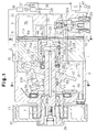
- a cylinder block 1 constitutes a part of the housing of the compressor.
- a front housing 2 is secured to the front end of the cylinder block 1.
- a rear housing 3 is secured to the rear end of the cylinder block 1 with a first plate 4, a second plate 70, a third plate 71 and a fourth plate 6.
- a crank chamber 2a is defined in the front housing 2.
- a drive shaft 9 is supported rotatably on the front housing 2 and the cylinder block 1. The front end of the drive shaft 9 protrudes outside the crank chamber 2a, with a pulley 10 secured to this front end.
- the pulley 10 is coupled to an engine of a vehicle via a belt 11.
- a support pipe 2b protrudes from the front end of the front housing 2 in such a way as to surround the front end of the drive shaft 9.
- the pulley 10 is supported via an angular bearing 7 on the support pipe 2b. Through the angular bearing 7, the support pipe 2b receives both the axial load and radial load which act on the pulley 10.
- a lip seal 12 is disposed between the front end of the drive shaft 9 and the front housing 2. The lip seal 12 prevents pressure leakage from the crank chamber 2a.
- a swash plate 15 is supported by the drive shaft 9 in such a way as to be slidable along and tiltable with respect to the axis L of the shaft 9.
- a pair of stays 16 and 17 are secured to the swash plate 15, with guide pins 18 and 19 fixed to the respective stays 16 and 17.
- Guide balls 18a and 19a are formed at the distal ends of the respective guide pins 18 and 19.
- a drive plate 8 is fixed to the drive shaft 9.
- the drive plate 8 has a support arm 8a protruding toward the swash plate 15 (rearward) from the drive plate 8.
- a pair of guide holes 8b and 8c are formed in the arm 8a, and the guide balls 18a and 19a are slidably fitted in the associated guide holes 8b and 8c.
- the cooperation of the arm 8a and the guide pins 18 and 19 permits the swash plate 15 to rotate together with the drive shaft 9 and to tilt with respect to the drive shaft 9.
- the tilting of the swash plate 15 is guided when the guide balls 18a, 19a slide in the associated guide holes 8b, 8c and the swash plate 15 slides along the axis L of the drive shaft 9.
- a first spring 41 is located between the drive plate 8 and the swash plate 15. The first spring 41 urges the swash plate 15 toward its minimum angle position.
- a shutter chamber 13 is formed in the center portion of the cylinder block 1, extending along the axis L of the drive shaft 9.
- a cylindrical spool 21 having one closed end is accommodated in the shutter chamber 13 in such a way as to be slidable along the axis L of the drive shaft 9.
- the spool 21 has a large diameter portion 21a and a small diameter portion 21b.
- a second spring 24 is located between the step portion between the large diameter portion 21a and small diameter portion 21b and the step portion of the inner wall of the shutter chamber 13. The second spring 24 urges the spool 21 toward the swash plate 15.
- the rear end of the drive shaft 9 is inserted in the spool 21.
- a radial bearing 25 is located between the rear end of the drive shaft 9 and the inner wall of the large diameter portion 21a of the spool 21.
- the radial bearing 25 has rollers 25a and an outer race 25b.
- the outer race 25b is fixed to the inner wall of the large diameter portion 21a.
- the rollers 25a are slidable along the axis L of the drive shaft 9.
- the rear end of the drive shaft 9 is supported by the inner wall of the shutter chamber 13 through the radial bearing 25 and the spool 21.
- a suction passage 26 is formed in the center portion of the rear housing 3, extending along the axis L of the drive shaft 9. As shown in Fig. 3, the suction passage 26 has a circular cross-section with its center coinciding with the axis L of the drive shaft 9. In other words, the suction passage 26 is defined along the axis of the drive shaft 9.
- the suction passage 26 communicates with the shutter chamber 13.
- a positioning surface 27 is formed on the second plate 70 between the shutter chamber 13 and the suction passage 26.
- the rear of the spool 21 constitutes a shutter surface 21c which is adapted to abut against the positioning surface 27. As the shutter surface 21c abuts against the positioning surface 27, the movement of the spool 21 in a direction away from the swash plate 15, or in the rearward direction, is restricted and the suction passage 26 is disconnected from the shutter chamber 13.
- a restriction 20 is formed integrally with the shutter surface 21c of the spool 21.
- a surface of the restriction 20 has a tapered first surface 20a at a distal end and a tapered second surface 20b at a proximal end.
- the restriction 20 has a circular cross-section with its center coinciding with the axis L of the drive shaft 9.
- the taper of the second surface 20b is more gradual than that of the first surface 20a with respect to the axis L.
- the restriction 20 may be advanced into the suction passage 26.
- the outer diameter of the proximal end of the restriction 20 is slightly smaller than the inner diameter of the suction passage 26. This results in a space defined between the outer surface of the restriction 20 and the inner wall of the suction passage 26.
- a thrust bearing 28 is slidably attached to the drive shaft 9 between the swash plate 15 and the spool 21.
- the thrust bearing 28 has rollers 28a and a pair of races 28b, 28c on opposite sides of the rollers 28a.
- a belleville spring 42 is disposed between the race 28c and the end face of the large diameter portion 21a of the spool 21.
- the thrust bearing 28 is constantly clamped between the swash plate 15 and the end face of the large diameter portion 21a of the spool 21 by the urging force of the second spring 24.
- the thrust bearing 28 prevents the rotation of the swash plate 15 from being transmitted to the spool 21.
- the rotation of the spool 21 would increase the load torque of the compressor. The torque would increase especially when the spool 21 rotates during abutment of the shutter surface 21c of the spool 21 with the positioning surface 27.
- the thrust bearing 28 prevents such increase of load torque.
- a plurality of cylinder bores 1a are formed in the cylinder block 1 in such a way as to communicate with the crank chamber 2a.
- single-headed pistons 22 are retained in the associated cylinder bores 1a.
- the hemispherical portions of a pair of shoes 23 are fitted on each piston 22 in a mutually slidable manner.
- the swash plate 15 is held between the flat portions of both shoes 23. Accordingly, the undulation of the swash plate 15 caused by the rotation of the drive shaft 9 is transmitted through the shoes 23 to each piston 22, so that each piston 22 reciprocates in the associated cylinder bore 1a in accordance with the inclination of the swash plate 15.
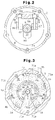
- a suction chamber 3a and a discharge chamber 3b are defined in the rear housing 3.
- Suction ports 4a and discharge ports 4b are formed in the first plate 4.
- Suction valves 70a are formed on the second plate 70, and discharge valves 71a are formed on the third plate 71.
- the refrigerant gas in the suction chamber 3a forces the associated suction valve 70a to open and flows into the associated cylinder bore 1a through the associated suction port 4a.
- the refrigerant gas in the cylinder bores 1a forces the associated discharge valve 71a to open and flows into the discharge chamber 3b through the associated discharge port 4b.
- As each discharge valve 71a abuts against a retainer 6a formed on the fourth plate 6, the degree of opening of the associated discharge valve 71a is restricted.
- a thrust bearing 29 is placed between the drive plate 8 and the front housing 2.
- the thrust bearing 29 receives the compressive reaction force, generated in the cylinder bores 1a, that acts on the drive plate 8 via the pistons 22, the shoes 23, the swash plate 15, the stays 16 and 17 and the guide pins 18, 19.
- the suction chamber 3a communicates with the shutter chamber 13 via a communication hole 4c.
- the communication hole 4c is blocked from the suction passage 26 when the shutter surface 21c of the spool 21 abuts against the positioning surface 27.
- a passage 30 is formed in the drive shaft 9.
- the passage 30 has an inlet 30a open to the crank chamber 2a in the vicinity of the lip seal 12, and an outlet 30b open to the interior of the spool 21.
- a pressure release hole 21d is formed in the surface of the small diameter portion 21b of the spool 21. The hole 21d communicates the interior of the spool 21 with the shutter chamber 13.
- a supply passage 31 connects the discharge chamber 3b to the crank chamber 2a.
- An electromagnetic valve 32 is attached to the rear housing 3 and is located midway in the supply passage 31.
- a valve body 34 closes a valve hole 32a.
- the solenoid 33 is de-excited, the valve body 34 opens the valve hole 32a. Therefore, the electromagnetic valve 32 selectively opens or closes the supply passage 31 between the discharge chamber 3b and the crank chamber 2a.
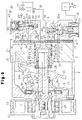
- An external refrigeration circuit 35 connects the suction passage 26 for supplying the refrigerant gas into the suction chamber 3a to the outlet port 1b for discharging the refrigerant gas from the discharge chamber 3b.
- a condenser 36 which is a thermal automatic expansion valve, controls the flow rate of the refrigerant in accordance with a change in gas temperature on the outlet side of the evaporator 38.
- a temperature sensor 39 is located near the evaporator 38. The temperature sensor 39 detects the temperature in the evaporator 38, and outputs a signal based on the detected temperature to a computer C.
- the computer C controls the solenoid 33 of the electromagnetic valve 32 based on the signal from the temperature sensor 39. More specifically, when the temperature detected by the temperature sensor 39 is equal to or below a predetermined value while an activation switch 40 of the air conditioning system is set on, the computer C de-excites the solenoid 33 to prevent frosting from taking place in the evaporator 38. The computer C de-excites the solenoid 33 when the activation switch 40 is switched off.
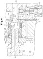
- Figs. 1 and 4 show the solenoid 33 in an excited state in which the supply passage 31 is closed. Therefore, the refrigerant gas under high pressure in the discharge chamber 3b is not supplied to the crank chamber 2a. In this situation, the refrigerant gas in the crank chamber 2a simply flows out to the suction chamber 3a via the passage 30 and the pressure release hole 21d so that the pressure in the crank chamber 2a approaches the low pressure in the suction chamber 3a, i.e., the suction pressure. As a result, the pressure difference between the crank chamber 2a and the cylinder bores 1a is reduced and the inclined angle of the swash plate 15 becomes maximized.
- the swash plate 15 is restricted not to incline beyond a predetermined maximum inclined angle. As a result, the inclined angle of the swash plate 15 is held at the maximum and the discharge displacement of the compressor is maximized. Since the refrigerant gas in the crank chamber 2a passes through the inlet 30a provided near the lip seal 12, the lubricating oil suspended in the refrigerant gas improves the lubrication and sealing between the lip seal 12 and the drive shaft 9.
- the computer C de-excites the solenoid 33.
- the supply passage 31 is opened to connect the discharge chamber 3b to the crank chamber 2a. Consequently, the refrigerant gas under high pressure in the discharge chamber 3b flows into the crank chamber 2a via the supply passage 31, raising the pressure in the crank chamber 2a. The difference between the pressure in the crank chamber 2a and the pressure in the cylinder bores 1a therefore increases and the inclined angle of the swash plate 15 becomes smaller.
- the spool 21 moves toward the positioning surface 27 while pressing the second spring 24 and contracting it as the inclined angle of the swash plate 15 is reduced.
- the restriction 20 enters the suction passage 26.
- the shutter surface 21c abuts against the positioning surface 27 and completely blocks the suction passage 26.
- a curve E shown in the graph of Fig. 7 shows the relationship between the discharge displacement of the compressor and the transitional cross-sectional area of the suction passage 26 in which gas flows through.
- Lines E1 and E2 indicate the transitional cross-sectional area defined by the space between the periphery of the distal end of the restriction 20 and the periphery of the outlet of the suction passage 26 when the restriction 20 is positioned separated from the suction passage 26.
- Line E3 indicates the transitional cross-sectional area when the first surface 20a of the restriction 20 starts advancing into the suction passage 26.
- Line E4 indicates the transitional cross-sectional area when the second surface 20b starts advancing into the suction passage 26.
- Line E5 indicates the transitional cross-sectional area defined by the shutter surface 21c of the spool 21 and a peripheral wall 26a of the suction passage 26.
- the alteration ratio of the transitional cross-sectional area in the suction passage 26 becomes moderate when the discharge displacement is small due to the tapered first and second surfaces 20a, 20b.
- the restricting effect resulting from the moderate alteration ratio of the transitional cross-sectional area gradually reduces the flow of the refrigerant gas from the suction passage 26 to the suction chamber 26.
- the amount of refrigerant gas drawn into the cylinder bores 1a from the suction chamber 3a is gradually reduced.
- the discharge pressure decreases gradually and does not greatly alter the load torque of the compressor within a short period of time. Therefore, alteration in load torque of the compressor becomes moderate when the discharge displacement is lowered from its maximum capacity to its minimum capacity. This reduces the impact produced by alteration in load torque.
- the value of the transitional cross-sectional area becomes zero when the shutter surface 21c of the spool 21 abuts against the positioning surface 27.
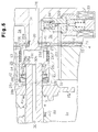
- the refrigerant gas in the external refrigeration circuit 35 does not flow into the suction chamber 3a. That is, the inclined angle of the swash plate 15 as shown in Fig. 5 inhibits the circulation of refrigerant gas between the external refrigeration circuit 35 and the compressor.
- the belleville spring 42 may be deformed to a flatter shape than the state shown in Fig. 5. That is, the inclined angle of the swash plate 15 which blocks the circulation of the refrigerant gas as shown in Fig. 5 may further be reduced to a smaller angle as shown in Fig. 6.
- the belleville spring 42 becomes flat as it is compressed between the race 28c of the thrust bearing 28 and the face end of the large diameter portion 21a of the spool 21.
- the race 28c of the thrust bearing 28 which prevents the rotation of the swash plate 15 from being transmitted to the spool 21, abuts against the entire inner rim of the belleville spring 42, thus allowing the spring 42 to be deformed into a flat state.
- Curve F shown in Fig. 8 indicates the spring characteristic of the belleville spring 42.
- the horizontal axis D represents deformation amount while the vertical axis represents spring force.
- the spring characteristic of the belleville spring is substantially constant at a certain deformation zone (in Fig. 8 between D1 and D2).
- Spring force G indicates the spring force of the second spring 24 when it is in the state as shown in Fig. 5, in which the spring 24 is most contracted.
- the spring force of the belleville spring 42 in the deformation zone (between D1 and D2) is set at a value larger than the value of the spring force G of the second spring.
- the spring force of the second spring 24 and the spring force of the belleville spring 42 enables the minimum inclined angle of the swash plate 15 to be smaller than the inclined angle which blocks the circulation of refrigerant gas.
- the spring force of the first spring 41 and the pressure inside the crank chamber 2a i.e., the force which urges the swash plate 15 to a direction reducing its inclination
- the spring force of the belleville spring 42 in the deformation zone is set at a value larger than the spring force of the belleville spring 42 in the deformation zone (between D1 and D2). Therefore, the swash plate 15 moves, as it deforms the belleville spring 42, from the inclined angle shown in Fig. 5, in which circulation of the refrigerant gas is blocked, to the minimum inclined angle shown in Fig. 6.
- the belleville spring 42 becomes flat as shown in Fig. 6, the deformation amount of the spring is D2.
- the amount of inclination shift of the swash plate 15 is small when the plate 15 shifts from the inclined angle blocking the circulation of refrigerant gas to the minimum inclined angle, and thus the deformation amount D2 of the belleville spring 42 is small.
- the belleville spring 14 is an optimal means for enabling the swash plate 15 to move from the inclined angle blocking the circulation of refrigerant gas to the minimum inclined angle.
- the inclined angle of the swash plate 15 is minimum.
- the minimum inclined angle of the swash plate 15 is restricted by the shutter surface 21c of the spool 21 abutting against the positioning surface 27 and the belleville spring 42 becoming flat.
- the positioning surface 27, spool 21, belleville spring 42 and thrust bearing 28 constitute a restricting means to restrict the minimum inclined angle of the swash plate 15.
- the minimum inclined angle of the swash plate 15 is slightly larger than zero degrees. The minimum inclined angle is reached by further tilting the swash plate 15 to an angle where the belleville spring 42 becomes flat from a closing position in which the spool 21 shuts the communication between the suction passage 26 and the shutter chamber 13. The spool 21 moves cooperatively with the swash plate 15 from the opening position to a separated closing position.
- the refrigerant gas is discharged into the discharge chamber 3b from the cylinder bores 1a even when the inclined angle of the swash plate 15 is minimized. Even when the inclined angle of the swash plate 15 is minimized, therefore, there a pressure difference exists between the discharge chamber 3b, the crank chamber 2a and the suction chamber 3a. The refrigerant gas discharged to the discharge chamber 3b from the cylinder bores 1a flows into the crank chamber 2a via the supply passage 31.
- the refrigerant gas in the crank chamber 2a flows into the suction chamber 3a via the passage 30 and the pressure release hole 21d, and the refrigerant gas in the suction chamber 3a is drawn into the cylinder bores 1a to be discharged to the discharge chamber 3b.
- a circulation path circulating the discharge chamber 3b, the supply passage 31, the crank chamber 2a, the passage 30, the pressure release hole 21d, the suction chamber 3a, and the cylinder bores 1a is formed in the compressor.
- the refrigerant gas circulates along this circulation path, and the lubricating oil suspended in the refrigerant gas lubricates the internal parts of the compressor.
- the belleville spring 42 which had been in a flat state as shown in Fig. 6 returns to its original form as shown in Fig. 5.
- the spool 21 is gradually separated from the positioning surface 27 by the spring force of the second spring 24. During this separation, the transitional cross-sectional area of the suction passage 26 is moderately increased.
- the amount of refrigerant gas which flows into the suction chamber 3a from the suction passage 26 gradually increases. This, in turn, gradually increases the amount of refrigerant gas drawn into the cylinder bores 1a and also gradually increases the discharge displacement of the compressor.
- the gradual increase in discharge pressure prevents the load torque of the compressor from being greatly altered in a short period of time.
- alteration in negative load torque of the compressor when the discharge displacement is increased from its minimum amount to its maximum amount becomes moderate, and the impact produced by the alteration becomes small.
- the lubricating oil, suspended in the refrigerant gas, inside the compressor flows out to the external refrigeration circuit 35 and returns into the compressor together with the refrigerant gas. It is necessary to maintain the flow of refrigerant gas in the external refrigerant circuit 35 above a predetermined amount to return the lubricating oil from the circuit 35. Therefore, when the inclined angle of the swash plate 15 is smaller than an angle which obtains the required flow amount, only refrigerant gas returns to the compressor. Since the lubricating oil, suspended in the refrigerant gas, inside the compressor keeps flowing out to the external refrigeration circuit 35, the amount of lubricating oil inside the compressor decreases and will be inadequate unless the oil is returned to the compressor.
- circulation of the refrigerant gas is blocked when the angle of the swash plate 15 is between its minimum inclined angle as shown in Fig. 6 and a larger inclined angle which blocks the circulation of the refrigerant gas as shown in Fig. 5.
- the inclined angle which blocks the circulation of the refrigerant gas is determined by a position at which a slightly larger inclined angle would enable a sufficient amount of refrigerant gas to flow in the external refrigeration circuit 35 and ensure the return of lubricating oil from the circuit 35.
- the circulation of the refrigerant gas between the external refrigeration circuit 35 and the compressor is blocked when the amount of refrigerant gas flowing in the circuit 35 is not sufficient to return the lubricating oil into the compressor.
- the minimum inclined angle of the swash plate 15 may be determined at an angle smaller than the angle which secures a flow amount of refrigerant gas sufficient to return the lubricating oil. This reduces in power loss.
- the supply of the refrigerant gas to the suction chamber 3a from the external refrigeration circuit 35 is allowed or inhibited by moving the spool 21 in response to the inclination of the swash plate 15.
- the use of this spool 21 effectively suppresses the torque change when the swash plate 15 is shifted between the maximum inclined angle and the minimum inclined angle.
- the opening and closing of the supply passage 31 are frequently repeated in accordance with a change in the cooling load of the compressor, the change-oriented shock is minimal because drastic changes in torque are suppressed by the action of the spool 21.
- the outlet of the suction passage 26 defined along the axis L of the drive shaft 9 is shut by the spool 21 which moves along the axis L.
- the force which presses the shutter surface 21c of the spool 21 against the positioning surface 27 to shut the suction passage 26 is obtained from the urging force in the direction reducing the inclined angle of the swash plate 15. This construction ensures a positive seal between the positioning surface 27 and the shutter surface 21c of the spool 21.
- a displacement control valve 43 is attached to the rear housing 3.
- the pressure in the crank chamber 2a is controlled by this control valve 43.
- a valve housing 44 which constitutes the control valve 43 is provided with a first port 44a, a second port 44b and a third port 44c.
- the first port 44a communicates with the discharge chamber 3b via a passage 45.
- the second port 44b communicates with the suction passage 26 via an inlet passage 46.
- the third port 44c communicates with the crank chamber 2a via a passage 47.
- a suction pressure detection chamber 49 communicates with the second port 44b.
- the pressure in this detection chamber 49 acts against an adjust spring 51 via a diaphragm 50.
- the spring force of the adjust spring 51 is transmitted to a valve body 53 with the diaphragm 50 and a rod 52.
- the urging force of a spring 54 acts on the valve body 53 in the direction to close a valve hole 44d.
- the valve body 53 opens or closes the valve hole 44d.
- the inclination of the swash plate 15 is variably controlled continuously between the minimum inclined angle and the maximum inclined angle according to changes in the opening size of the control valve 43 which corresponds to the cooling load.
- the computer C excites and de-excites the solenoid 33 of the electromagnetic valve 32 based on the ON/OFF action of the activation switch 40.
- a coil spring 57 is interposed by the thrust bearing 28 and the radial bearing 25.
- One end of the coil spring 57 abuts against the race 28c of the thrust bearing 28 while the other end of the spring 57 abuts against the outer race 25b of the radial bearing 25.
- the coil spring 57 transmits the movement of the swash plate 15 to the spool 21 via the radial bearing 25.
- the spring force of the coil spring 57 is greater than that of the second spring 24.
- the coil spring 57 is becomes contracted after contraction of the second spring 24 abuts the shutter surface 21c against the positioning surface 27.
- the swash plate 15 can be further inclined from the inclined angle which shuts the circulation of the refrigerant gas, as shown in the solid lines of Fig. 10, to a smaller angle.
- the two-dotted line on the left side of Fig. 10 shows the swash plate 15 at the maximum inclined angle while the two-dotted line on the right side shows the swash plate 15 at the minimum inclined angle.
- the minimum inclined angle of the swash plate 15 is restricted by the race 28c of the thrust bearing 28 abutting against the end face of the spool 21.
- the lubricating oil is always suspended in the refrigerant gas when returning to the compressor during circulation between the external refrigeration circuit 35 and the compressor. This eliminates cases where the gas returns without the oil. As a result, a reduction of the amount of oil in the compressor is prevented. Thus, lubrication insufficiency does not take place.
- the minimum inclined angle of the swash plate 15 may be determined at an angle smaller than the angle which secures a flow amount of refrigerant gas sufficient to return the lubricating oil. This reduces power loss.
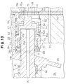
- a support cylinder 58 is slidably retained in the shutter chamber 13.
- the shutter chamber 13 has a large diameter portion 58a and a small diameter portion 58b.
- a spool 59 is slidably supported on the small diameter portion 58b.
- a belleville spring 60 is located between a stepped portion, defined between the large diameter portion 58a and the small diameter portion 58b, and a flange 59a of the spool 59.
- a pressure release hole 59b is formed in the peripheral wall of the spool 59.
- the second spring 24 is between the flange 59a and the inner surface of the shutter chamber 13. The release hole 59b communicates the inside of the spool 59 with the shutter chamber 13.
- Movement of the swash plate 15 is transmitted to the spool 59 via the thrust bearing 28, the supporter cylinder 58, and the belleville spring 60.
- the suction passage 26 is shut by the abutment between a shutter surface 59c of the spool 59 and the positioning surface 27.
- a restriction 72 is formed integrally with the shutter surface 59c of the spool 59.
- a tapered first surface 72a is provided at the distal end while a tapered second portion 72b is provided at the proximal end.
- the spring force of the belleville spring 60 being greater than that of the second spring 24, deforms the spring 60 into a flat shape after the second spring 24 is contracted for abutment between the shutter surface 59c and the positioning surface 27. Accordingly, the swash plate 15 can be further inclined from the inclined angle which shuts the circulation of the refrigerant gas, as shown in the solid lines of Fig. 12, to a smaller angle while deforming the belleville spring 60 into a flat shape.
- the two-dotted line of Fig. 12 shows the swash plate 15 at the minimum inclined angle.
- the lubricating oil is always suspended in the refrigerant gas when returning to the compressor during circulation between the external refrigeration circuit 35 and the compressor. This eliminates cases in which the gas returns without the oil. As a result, a reduction of the amount of oil in the compressor is prevented. Thus, lubrication insufficiency does not take place.
- the minimum inclined angle of the swash plate 15 may be determined at an angle smaller than the angle which secures a flow amount of refrigerant gas sufficient enough to return the lubricating oil. This reduces power loss.
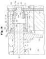
- a cylindrical restriction 61 is slidably accommodated in the shutter chamber 13.
- the restriction 61 has a large diameter portion 73, a small diameter portion 74, and a restricting projection 75.
- a tapered first and second surface 75a, 75b is provided at its distal end.
- a cylindrical third surface 75c is provided at the proximal end.
- a spool 62 is slidably supported by the small diameter portion 74 and the third surface 75c.
- a belleville spring 63 is located between a stepped portion, which is between the small and large diameter portions 73, 74, and a flange 62a of the spool 62.
- the second spring 24 is between the flange 62a and the inner surface of the shutter chamber 13.
- a pressure release hole 61a is formed in the stepped portion between the large and small diameter portions 73, 74.
- the release hole 61a communicates the inside of the restriction 61 with the shutter chamber 13.
- the movement of the swash plate 15 is transmitted to the spool 62 via the thrust bearing 28, the restriction 61, and the belleville spring 63.
- the suction passage 26 is shut by the abutment of a shutter surface 62b of the spool 62 with the positioning surface 27.
- the spring force of the belleville spring 63 being greater than that of the second spring 24, deforms the spring 63 into a flat shape after the second spring 24 is contracted for abutment between the shutter surface 62b and the positioning surface 27. Accordingly, the swash plate 15 can be further inclined from the inclined angle which shuts the circulation of the refrigerant gas as shown in the solid lines of Fig. 14 to a smaller angle while deforming the belleville spring 63 into a flat shape.
- the two-dotted line of Fig. 14 shows the swash plate 15 at the minimum inclined angle.
- the lubricating oil is always suspended in the refrigerant gas when returning to the compressor during circulation between the external refrigeration circuit 35 and the compressor. This eliminates cases in which the gas returns without the oil. As a result, a reduction of the amount of oil in the compressor is prevented. Thus, lubrication insufficiency does not take place.
- the minimum inclined angle of the swash plate 15 may be determined at an angle smaller than the angle which results in a flow amount of refrigerant gas sufficient to return the lubricating oil. This reduces power loss.
- a support cylinder 64 is slidably accommodated in the shutter chamber 13.
- a flange 64a is formed on the inner surface of the support cylinder 64.
- a flange 65a is formed on the outer surface of the spool 65.
- a belleville spring 66 is disposed between the two flanges 64a, 65a.
- the second spring 24 is disposed between the flange 65a and the inner surface of the shutter chamber 13.
- a pressure release hole 65b communicates the inside of the spool 65 with the shutter chamber 13. The movement of the swash plate 15 is transmitted to the spool 65 via the thrust bearing 28, the support cylinder 64, and the belleville spring 66.
- the suction passage 26 is shut by the abutment of the shutter surface 65c of the spool 65 with the positioning surface 27.
- a restriction 76 is formed integrally with the shutter surface 65c of the spool 65.
- a tapered first surface 76a is provided at the distal end while a tapered second portion 76b is provided at the proximal end.
- the spring force of the belleville spring 66 being greater than that of the second spring 24, deforms the spring 66 into a flat shape after the second spring 24 is contracted for abutment between the shutter surface 65c and the positioning surface 27. Accordingly, the swash plate 15 can be further inclined from the inclined angle which inhibits the circulation of the refrigerant gas as shown in the solid lines of Fig. 16 to a smaller angle while deforming the belleville spring 63 into a flat shape.
- the two-dotted line of Fig. 16 shows the swash plate 15 at the minimum inclined angle.
- the lubricating oil is always suspended in the refrigerant gas when returning to the compressor during circulation between the external refrigeration circuit 35 and the compressor. This eliminates cases in which the gas returns without the oil. As a result, a reduction of the amount of oil in the compressor is prevented. Thus, lubrication insufficiency does not take place.
- the minimum inclined angle of the swash plate 15 may be determined at an angle smaller than the angle which enables a flow amount of refrigerant gas sufficient to return the lubricating oil. This reduces power loss.
- a compressor has a swash plate (15) tiltable between maximum and minimum inclining angles with respect to a plane perpendicular to an axis of a drive shaft (9) according to a difference between pressures in a crank chamber (2a) and a suction chamber (3a).
- An internal gas passage (2a, 3a, 3b, 30, 31) includes the crank chamber (2a), the suction chamber (3a) and a discharge chamber (3b).
- the internal gas passage is connected to an external circuit (35) separately provided from the compressor.
- the rotation of the drive shaft (9) is converted to a reciprocating movement of a piston (22) to vary a capacity of a cylinder bore (1a).
- the piston (22) compresses a gas supplied from the external circuit (35) to the internal gas passage (2a, 3a, 3b, 30, 31) and discharges the gas to the external circuit (35).
- a inhibiting apparatus (21, 28, 42; 21, 28, 57; 28, 58, 59, 60; 28, 61, 62, 63; 28, 64, 65, 66) inhibits the circulation of the gas through the internal gas passage (2a, 3a, 3b, 30, 31) and the external circuit (35) when the swash plate (15) is located between the minimum inclining angle and a first inclining angle.
- the first inclining angle is greater than the minimum inclining angle of the swash plate (15).
Landscapes
- Engineering & Computer Science (AREA)
- Mechanical Engineering (AREA)
- General Engineering & Computer Science (AREA)
- Compressors, Vaccum Pumps And Other Relevant Systems (AREA)
- Compressor (AREA)
Applications Claiming Priority (2)
| Application Number | Priority Date | Filing Date | Title |
|---|---|---|---|
| JP6303940A JP2932952B2 (ja) | 1994-12-07 | 1994-12-07 | クラッチレス可変容量型圧縮機 |
| JP303940/94 | 1994-12-07 |
Publications (2)
| Publication Number | Publication Date |
|---|---|
| EP0716228A1 true EP0716228A1 (fr) | 1996-06-12 |
| EP0716228B1 EP0716228B1 (fr) | 1999-03-17 |
Family
ID=17927125
Family Applications (1)
| Application Number | Title | Priority Date | Filing Date |
|---|---|---|---|
| EP95119209A Expired - Lifetime EP0716228B1 (fr) | 1994-12-07 | 1995-12-06 | Compresseur à piston à déplacement variable |
Country Status (5)
| Country | Link |
|---|---|
| US (1) | US5636973A (fr) |
| EP (1) | EP0716228B1 (fr) |
| JP (1) | JP2932952B2 (fr) |
| KR (1) | KR0167632B1 (fr) |
| DE (1) | DE69508359T2 (fr) |
Cited By (6)
| Publication number | Priority date | Publication date | Assignee | Title |
|---|---|---|---|---|
| FR2756876A1 (fr) * | 1996-12-10 | 1998-06-12 | Toyoda Automatic Loom Works | Compresseur a deplacement variable pour appareil de conditionnement d'air d'un vehicule |
| FR2763376A1 (fr) * | 1997-05-14 | 1998-11-20 | Toyoda Automatic Loom Works | Soupape de commande d'un compresseur a deplacement variable pour climatiseur d'air de vehicule, et compresseur comprenant une telle soupape |
| EP0812987A3 (fr) * | 1996-06-07 | 1999-06-02 | Kabushiki Kaisha Toyoda Jidoshokki Seisakusho | Compresseur à capacité variable |
| EP0824191A3 (fr) * | 1996-08-12 | 1999-06-09 | Kabushiki Kaisha Toyoda Jidoshokki Seisakusho | Compresseur à déplacement variable |
| WO2003029654A1 (fr) * | 2001-09-28 | 2003-04-10 | Zexel Valeo Climate Control Corporation | Compresseur |
| EP2853740A1 (fr) * | 2013-09-25 | 2015-04-01 | Kabushiki Kaisha Toyota Jidoshokki | Compresseur à déplacement variable de type plateau oscillant |
Families Citing this family (25)
| Publication number | Priority date | Publication date | Assignee | Title |
|---|---|---|---|---|
| KR100203975B1 (ko) * | 1995-10-26 | 1999-06-15 | 이소가이 치세이 | 캠 플레이트식 가변용량 압축기 |
| JP3733633B2 (ja) * | 1996-02-01 | 2006-01-11 | 株式会社豊田自動織機 | 可変容量圧縮機 |
| JPH09256947A (ja) * | 1996-03-19 | 1997-09-30 | Toyota Autom Loom Works Ltd | 圧縮機における弁座構造 |
| US5813841A (en) * | 1996-05-16 | 1998-09-29 | Sturman Industries | Hydraulic pressure control system for a pump |
| KR100215157B1 (ko) * | 1996-06-19 | 1999-08-16 | 이소가이 지세이 | 가변용량 압축기 및 그 부착방법 |
| JPH10148177A (ja) * | 1996-11-20 | 1998-06-02 | Toyota Autom Loom Works Ltd | 可変容量型圧縮機 |
| JP2000186668A (ja) * | 1998-12-22 | 2000-07-04 | Toyota Autom Loom Works Ltd | 可変容量型圧縮機における容量制御構造 |
| JP2000283028A (ja) * | 1999-03-26 | 2000-10-10 | Toyota Autom Loom Works Ltd | 可変容量型圧縮機 |
| JP2002021720A (ja) * | 2000-07-06 | 2002-01-23 | Toyota Industries Corp | 容量可変型圧縮機の制御弁 |
| ITBO20010625A1 (it) * | 2001-10-12 | 2003-04-12 | Magneti Marelli Powertrain Spa | Pompa ad alta pressione a portata variabile |
| US6755625B2 (en) | 2002-10-07 | 2004-06-29 | Robert H. Breeden | Inlet throttle valve |
| JP4479504B2 (ja) * | 2004-04-28 | 2010-06-09 | 株式会社豊田自動織機 | 可変容量圧縮機 |
| JP4412184B2 (ja) * | 2005-01-27 | 2010-02-10 | 株式会社豊田自動織機 | 可変容量型圧縮機 |
| JP4973066B2 (ja) * | 2006-08-25 | 2012-07-11 | 株式会社豊田自動織機 | 圧縮機及び圧縮機の作動方法 |
| FR2916812B1 (fr) * | 2007-06-01 | 2011-09-02 | Halla Climate Control Corp | Compresseur a plateau cyclique a capacite variable. |
| JP5222447B2 (ja) * | 2008-06-11 | 2013-06-26 | サンデン株式会社 | 可変容量圧縮機 |
| BE1021737B1 (nl) * | 2013-09-11 | 2016-01-14 | Atlas Copco Airpower, Naamloze Vennootschap | Vloeistofgeinjecteerde schroefcompressor, sturing voor de overgang van een onbelaste naar een belaste situatie van zulke schroefcompressor en werkwijze daarbij toegepast |
| JP6179439B2 (ja) * | 2014-03-28 | 2017-08-16 | 株式会社豊田自動織機 | 容量可変型斜板式圧縮機 |
| JP6191527B2 (ja) | 2014-03-28 | 2017-09-06 | 株式会社豊田自動織機 | 容量可変型斜板式圧縮機 |
| JP6194837B2 (ja) | 2014-03-28 | 2017-09-13 | 株式会社豊田自動織機 | 容量可変型斜板式圧縮機 |
| JP6179438B2 (ja) | 2014-03-28 | 2017-08-16 | 株式会社豊田自動織機 | 容量可変型斜板式圧縮機 |
| JP6194836B2 (ja) | 2014-03-28 | 2017-09-13 | 株式会社豊田自動織機 | 容量可変型斜板式圧縮機 |
| JP6287483B2 (ja) | 2014-03-28 | 2018-03-07 | 株式会社豊田自動織機 | 容量可変型斜板式圧縮機 |
| DE102015204385A1 (de) * | 2015-03-11 | 2016-09-15 | Mahle International Gmbh | Axialkolbenmaschine |
| KR102692484B1 (ko) * | 2019-05-20 | 2024-08-07 | 현대자동차주식회사 | 차량의 공기조화 시스템, 공기조화 시스템용 전자제어밸브 및 공기조화 시스템의 제어방법 |
Citations (5)
| Publication number | Priority date | Publication date | Assignee | Title |
|---|---|---|---|---|
| EP0340024A1 (fr) * | 1988-04-28 | 1989-11-02 | Sanden Corporation | Compresseur du type à plateau en biais avec mécanisme à déplacement variable |
| US5173032A (en) | 1989-06-30 | 1992-12-22 | Matsushita Electric Industrial Co., Ltd. | Non-clutch compressor |
| EP0628722A1 (fr) * | 1993-06-08 | 1994-12-14 | Kabushiki Kaisha Toyoda Jidoshokki Seisakusho | Compresseur à plateau oblique |
| DE4439512A1 (de) * | 1993-11-05 | 1995-05-11 | Toyoda Automatic Loom Works | Kolbenverdichter mit änderbarer Verdrängung |
| DE4446832A1 (de) * | 1993-12-27 | 1995-06-29 | Toyoda Automatic Loom Works | Kupplungsloser verdrängungsvariabler Kolbenkompressor |
Family Cites Families (3)
| Publication number | Priority date | Publication date | Assignee | Title |
|---|---|---|---|---|
| US5577894A (en) * | 1993-11-05 | 1996-11-26 | Kabushiki Kaisha Toyoda Jidoshokki Seisakusho | Piston type variable displacement compressor |
| US5529461A (en) * | 1993-12-27 | 1996-06-25 | Kabushiki Kaisha Toyoda Jidoshokki Seisakusho | Piston type variable displacement compressor |
| WO1995024557A1 (fr) * | 1994-03-09 | 1995-09-14 | Kabushiki Kaisha Toyoda Jidoshokki Seisakusho | Compresseur du type a cylindree variable |
-
1994
- 1994-12-07 JP JP6303940A patent/JP2932952B2/ja not_active Expired - Fee Related
-
1995
- 1995-11-28 KR KR1019950044078A patent/KR0167632B1/ko not_active Expired - Fee Related
- 1995-12-06 US US08/568,158 patent/US5636973A/en not_active Expired - Fee Related
- 1995-12-06 EP EP95119209A patent/EP0716228B1/fr not_active Expired - Lifetime
- 1995-12-06 DE DE69508359T patent/DE69508359T2/de not_active Expired - Fee Related
Patent Citations (5)
| Publication number | Priority date | Publication date | Assignee | Title |
|---|---|---|---|---|
| EP0340024A1 (fr) * | 1988-04-28 | 1989-11-02 | Sanden Corporation | Compresseur du type à plateau en biais avec mécanisme à déplacement variable |
| US5173032A (en) | 1989-06-30 | 1992-12-22 | Matsushita Electric Industrial Co., Ltd. | Non-clutch compressor |
| EP0628722A1 (fr) * | 1993-06-08 | 1994-12-14 | Kabushiki Kaisha Toyoda Jidoshokki Seisakusho | Compresseur à plateau oblique |
| DE4439512A1 (de) * | 1993-11-05 | 1995-05-11 | Toyoda Automatic Loom Works | Kolbenverdichter mit änderbarer Verdrängung |
| DE4446832A1 (de) * | 1993-12-27 | 1995-06-29 | Toyoda Automatic Loom Works | Kupplungsloser verdrängungsvariabler Kolbenkompressor |
Cited By (8)
| Publication number | Priority date | Publication date | Assignee | Title |
|---|---|---|---|---|
| EP0812987A3 (fr) * | 1996-06-07 | 1999-06-02 | Kabushiki Kaisha Toyoda Jidoshokki Seisakusho | Compresseur à capacité variable |
| EP0824191A3 (fr) * | 1996-08-12 | 1999-06-09 | Kabushiki Kaisha Toyoda Jidoshokki Seisakusho | Compresseur à déplacement variable |
| US6135722A (en) * | 1996-08-12 | 2000-10-24 | Kabushiki Kaisha Toyoda Jidoshokki Seisakusho | Positional relationship of a bearing in the shutoff member of a variable displacement compressor |
| CN1102699C (zh) * | 1996-08-12 | 2003-03-05 | 株式会社丰田自动织机制作所 | 可变容量压缩机 |
| FR2756876A1 (fr) * | 1996-12-10 | 1998-06-12 | Toyoda Automatic Loom Works | Compresseur a deplacement variable pour appareil de conditionnement d'air d'un vehicule |
| FR2763376A1 (fr) * | 1997-05-14 | 1998-11-20 | Toyoda Automatic Loom Works | Soupape de commande d'un compresseur a deplacement variable pour climatiseur d'air de vehicule, et compresseur comprenant une telle soupape |
| WO2003029654A1 (fr) * | 2001-09-28 | 2003-04-10 | Zexel Valeo Climate Control Corporation | Compresseur |
| EP2853740A1 (fr) * | 2013-09-25 | 2015-04-01 | Kabushiki Kaisha Toyota Jidoshokki | Compresseur à déplacement variable de type plateau oscillant |
Also Published As
| Publication number | Publication date |
|---|---|
| US5636973A (en) | 1997-06-10 |
| KR0167632B1 (ko) | 1999-03-20 |
| EP0716228B1 (fr) | 1999-03-17 |
| JPH08159023A (ja) | 1996-06-18 |
| DE69508359D1 (de) | 1999-04-22 |
| KR960023778A (ko) | 1996-07-20 |
| DE69508359T2 (de) | 1999-10-14 |
| JP2932952B2 (ja) | 1999-08-09 |
Similar Documents
| Publication | Publication Date | Title |
|---|---|---|
| EP0716228B1 (fr) | Compresseur à piston à déplacement variable | |
| EP0748937B1 (fr) | Dispositif de commande de déplacement pour un compresseur à déplacement variable sans embrayage | |
| US5584670A (en) | Piston type variable displacement compressor | |
| US5577894A (en) | Piston type variable displacement compressor | |
| EP0628722B1 (fr) | Compresseur à plateau oblique | |
| US6227812B1 (en) | Refrigerant circuit and compressor | |
| US5964578A (en) | Control valve in variable displacement compressor | |
| US5890876A (en) | Control valve in variable displacement compressor | |
| US5681150A (en) | Piston type variable displacement compressor | |
| EP0848164B1 (fr) | Soupape de contrôle pour compresseur à capacité variable | |
| EP1384889B1 (fr) | Appareil de commande pour compresseur à déplacement variable | |
| US6358017B1 (en) | Control valve for variable displacement compressor | |
| EP0953765B1 (fr) | Compresseur en plateau en biais à capacité variable avec soupape de contrôle | |
| US5603610A (en) | Clutchless piston type variable displacement compressor | |
| EP0635640B1 (fr) | Structure de palier utilisée dans un compresseur | |
| US5842834A (en) | Swash plate type compressor employing single-headed pistons | |
| EP0824191B1 (fr) | Compresseur à déplacement variable | |
| EP0919720A2 (fr) | Soupape de contrÔle pour compresseur à capacité variable | |
| US5616008A (en) | Variable displacement compressor | |
| US6443707B1 (en) | Control valve for variable displacement compressor | |
| US5741122A (en) | Variable displacement compressor having a spool with a coating layer | |
| US20020094278A1 (en) | Apparatus and method for controlling variable displacement compressor | |
| US5713725A (en) | Clutchless piston type variable displacement compressor | |
| US6578372B2 (en) | Apparatus and method for controlling variable displacement compressor | |
| EP0844392A2 (fr) | Compresseur à déplacement variable |
Legal Events
| Date | Code | Title | Description |
|---|---|---|---|
| PUAI | Public reference made under article 153(3) epc to a published international application that has entered the european phase |
Free format text: ORIGINAL CODE: 0009012 |
|
| 17P | Request for examination filed |
Effective date: 19951206 |
|
| AK | Designated contracting states |
Kind code of ref document: A1 Designated state(s): DE FR GB IT |
|
| 17Q | First examination report despatched |
Effective date: 19970425 |
|
| GRAG | Despatch of communication of intention to grant |
Free format text: ORIGINAL CODE: EPIDOS AGRA |
|
| GRAG | Despatch of communication of intention to grant |
Free format text: ORIGINAL CODE: EPIDOS AGRA |
|
| GRAH | Despatch of communication of intention to grant a patent |
Free format text: ORIGINAL CODE: EPIDOS IGRA |
|
| GRAH | Despatch of communication of intention to grant a patent |
Free format text: ORIGINAL CODE: EPIDOS IGRA |
|
| GRAA | (expected) grant |
Free format text: ORIGINAL CODE: 0009210 |
|
| AK | Designated contracting states |
Kind code of ref document: B1 Designated state(s): DE FR GB IT |
|
| ITF | It: translation for a ep patent filed | ||
| REF | Corresponds to: |
Ref document number: 69508359 Country of ref document: DE Date of ref document: 19990422 |
|
| ET | Fr: translation filed | ||
| PLBE | No opposition filed within time limit |
Free format text: ORIGINAL CODE: 0009261 |
|
| STAA | Information on the status of an ep patent application or granted ep patent |
Free format text: STATUS: NO OPPOSITION FILED WITHIN TIME LIMIT |
|
| 26N | No opposition filed | ||
| REG | Reference to a national code |
Ref country code: GB Ref legal event code: IF02 |
|
| PGFP | Annual fee paid to national office [announced via postgrant information from national office to epo] |
Ref country code: GB Payment date: 20041201 Year of fee payment: 10 |
|
| PGFP | Annual fee paid to national office [announced via postgrant information from national office to epo] |
Ref country code: DE Payment date: 20041202 Year of fee payment: 10 |
|
| PGFP | Annual fee paid to national office [announced via postgrant information from national office to epo] |
Ref country code: FR Payment date: 20041208 Year of fee payment: 10 |
|
| PG25 | Lapsed in a contracting state [announced via postgrant information from national office to epo] |
Ref country code: IT Free format text: LAPSE BECAUSE OF NON-PAYMENT OF DUE FEES Effective date: 20051206 Ref country code: GB Free format text: LAPSE BECAUSE OF NON-PAYMENT OF DUE FEES Effective date: 20051206 |
|
| PG25 | Lapsed in a contracting state [announced via postgrant information from national office to epo] |
Ref country code: DE Free format text: LAPSE BECAUSE OF NON-PAYMENT OF DUE FEES Effective date: 20060701 |
|
| GBPC | Gb: european patent ceased through non-payment of renewal fee |
Effective date: 20051206 |
|
| PG25 | Lapsed in a contracting state [announced via postgrant information from national office to epo] |
Ref country code: FR Free format text: LAPSE BECAUSE OF NON-PAYMENT OF DUE FEES Effective date: 20060831 |
|
| REG | Reference to a national code |
Ref country code: FR Ref legal event code: ST Effective date: 20060831 |