EP0716409A2 - Système de codage de parole - Google Patents
Système de codage de parole Download PDFInfo
- Publication number
- EP0716409A2 EP0716409A2 EP95119147A EP95119147A EP0716409A2 EP 0716409 A2 EP0716409 A2 EP 0716409A2 EP 95119147 A EP95119147 A EP 95119147A EP 95119147 A EP95119147 A EP 95119147A EP 0716409 A2 EP0716409 A2 EP 0716409A2
- Authority
- EP
- European Patent Office
- Prior art keywords
- fft
- signal
- circuit
- block length
- gain
- Prior art date
- Legal status (The legal status is an assumption and is not a legal conclusion. Google has not performed a legal analysis and makes no representation as to the accuracy of the status listed.)
- Granted
Links
- 238000004364 calculation method Methods 0.000 claims description 27
- 238000011156 evaluation Methods 0.000 claims description 20
- 230000006870 function Effects 0.000 claims description 16
- 238000000034 method Methods 0.000 claims description 11
- 230000008569 process Effects 0.000 claims description 8
- 238000005259 measurement Methods 0.000 claims description 7
- 238000012545 processing Methods 0.000 description 12
- 230000003044 adaptive effect Effects 0.000 description 8
- 230000006872 improvement Effects 0.000 description 6
- 239000008187 granular material Substances 0.000 description 5
- 230000000873 masking effect Effects 0.000 description 5
- 238000013139 quantization Methods 0.000 description 5
- 230000009467 reduction Effects 0.000 description 5
- 230000006866 deterioration Effects 0.000 description 4
- 230000008859 change Effects 0.000 description 3
- 238000012937 correction Methods 0.000 description 2
- 230000005540 biological transmission Effects 0.000 description 1
- 239000000470 constituent Substances 0.000 description 1
- 238000010276 construction Methods 0.000 description 1
- 230000000694 effects Effects 0.000 description 1
- 238000001914 filtration Methods 0.000 description 1
- 238000012986 modification Methods 0.000 description 1
- 230000004048 modification Effects 0.000 description 1
- 230000003595 spectral effect Effects 0.000 description 1
- 238000001228 spectrum Methods 0.000 description 1
- 230000001629 suppression Effects 0.000 description 1
Images


Classifications
-
- G—PHYSICS
- G10—MUSICAL INSTRUMENTS; ACOUSTICS
- G10L—SPEECH ANALYSIS TECHNIQUES OR SPEECH SYNTHESIS; SPEECH RECOGNITION; SPEECH OR VOICE PROCESSING TECHNIQUES; SPEECH OR AUDIO CODING OR DECODING
- G10L19/00—Speech or audio signals analysis-synthesis techniques for redundancy reduction, e.g. in vocoders; Coding or decoding of speech or audio signals, using source filter models or psychoacoustic analysis
- G10L19/02—Speech or audio signals analysis-synthesis techniques for redundancy reduction, e.g. in vocoders; Coding or decoding of speech or audio signals, using source filter models or psychoacoustic analysis using spectral analysis, e.g. transform vocoders or subband vocoders
- G10L19/0212—Speech or audio signals analysis-synthesis techniques for redundancy reduction, e.g. in vocoders; Coding or decoding of speech or audio signals, using source filter models or psychoacoustic analysis using spectral analysis, e.g. transform vocoders or subband vocoders using orthogonal transformation
-
- G—PHYSICS
- G10—MUSICAL INSTRUMENTS; ACOUSTICS
- G10L—SPEECH ANALYSIS TECHNIQUES OR SPEECH SYNTHESIS; SPEECH RECOGNITION; SPEECH OR VOICE PROCESSING TECHNIQUES; SPEECH OR AUDIO CODING OR DECODING
- G10L25/00—Speech or voice analysis techniques not restricted to a single one of groups G10L15/00 - G10L21/00
- G10L25/03—Speech or voice analysis techniques not restricted to a single one of groups G10L15/00 - G10L21/00 characterised by the type of extracted parameters
- G10L25/18—Speech or voice analysis techniques not restricted to a single one of groups G10L15/00 - G10L21/00 characterised by the type of extracted parameters the extracted parameters being spectral information of each sub-band
-
- G—PHYSICS
- G10—MUSICAL INSTRUMENTS; ACOUSTICS
- G10L—SPEECH ANALYSIS TECHNIQUES OR SPEECH SYNTHESIS; SPEECH RECOGNITION; SPEECH OR VOICE PROCESSING TECHNIQUES; SPEECH OR AUDIO CODING OR DECODING
- G10L25/00—Speech or voice analysis techniques not restricted to a single one of groups G10L15/00 - G10L21/00
- G10L25/27—Speech or voice analysis techniques not restricted to a single one of groups G10L15/00 - G10L21/00 characterised by the analysis technique
Definitions
- the present invention relates to speech coding systems and, more particularly, to speech coding system conforming to layer III standardized algorithm.
- Standardization of the coding techniques for transmitting or storing analog speech signal faithfully to an original speech has been promoted by CCITT (Committee of Consultation of International Telephone and Telephone) and the like.
- CCITT Common Callittee of Consultation of International Telephone and Telephone
- a sub-band coding system and an adaptive transform coding system. These coding systems are common in that they utilize signal energy that is partially found in a band which far surpasses the speech signal band for improving the coding efficiency.
- the input signal is divided into a plurality of sub-bands for bit assignment in correspondence to the signal energy of each sub-band.
- the adaptive transform coding system the input signal is subjected to linear transform for quantizing the signal in a state of enhanced power concentration. For the linear transform, Fourier transform or cosine transform is usually adopted.
- a method of utilizing the psychological acoustical characteristics is to execute a certain type of weighting (psychological acoustical weighting) when the quantizing signal in order to minimize deterioration of the signal in the frequency band that is readily sensible by the person.
- the psychological acoustical weighting is to determine successive corrected audible threshold values from a relative audible threshold value that is determined by the relation between an absolute audible threshold value (the threshold value here being related to the sound pressure) and a masking effect.
- the bit assignment is made according to the result of the weighting.
- a prior art example will now be described in detail.
- a person can sense only sound pressures that are above the absolute audible threshold value.
- a low sound pressure frequency component which is located in the vicinity of a high sound pressure frequency component (i.e., a masker) can not be sensed due to the influence of the Mask (i.e., masking effect).
- the masking effect has an asymmetrical characteristic on the opposite sides of the masker, and it is provided in a wider range on the lower frequency side of the masker rather than the high frequency side. It is thus possible to make efficient coding by making bit assignment to frequency components above the corrected audible threshold value in correspondence to the difference between the sound pressure and corrected audible threshold value of these frequency components.
- a plurality of samples are subjected as a block to the linear transform.
- increasing the block length for linear transform permits increased resolution to be obtained to improve the coding quality.
- the linear transform executed with a large block length on a sharp amplitude rise portion of the speech signal results in generation of preceding noise or commonly called pre-echo when the coded speech signal is decoded. This is attributable to noise generation in a portion of one block in which the signal amplitude is changed sharply, that is, to the fact that the quantization distortion uniformly distributing in one block is sensed in a small signal amplitude portion.
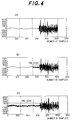
- Figs. 4(A) to 4(C) show how pre-echo varies with the block length in the linear transform when drums are used as sound source for measurement.
- noise is generated prior to a sharp signal amplitude rise portion (i.e., attack portion).
- a standard algorithm used for the adaptive block length coding adopts a three hierarchy layer structure in correspondence to such factor as the coding quality required for the adopted bit rate or the complexity of the system.
- layer III seeks coding quality improvement compared to layers I and II.
- the layer III utilizes adaptive block length for suppressing the pre-echo when each sub-band signal of the input signal is converted into the frequency domain through MDCT (modified discrete cosine transform).
- a filtering operation with window function is executed by providing a 50 % overlap between adjacent blocks lest discontinuity of quantized noise should be sensed as block distortion in the neighborhood of block boundaries.
- an off-set is introduced into the time term of discrete cosine transform which is calculated subsequently to obtain symmetrical transform coefficients.
- the transform coefficients requiring coding become one half the overlapped block length 2N, thus permitting off-setting of the efficiency deterioration resulting from the 50 % overlap.
- the basic concept of the adaptive block length introduced into the MDCT system is based on a psycholorigcal acoustical model.
- the speech coding system comprises a linear transform unit 50 for executing linear transform of an input signal Si with a predetermined block length, an FFT unit 60 for executing Fast Fourier transform of the input signal Si with two different block lengths, a block length setting unit 70 for calculating a predetermined block length Sb to be set in the linear transform unit 50 according to an FFT signal produced by the FFT unit 60 and setting this block length Sb in the linear transform unit 50, and a coding unit 80 for coding an intermediate signal Sm produced by the linear transform unit 50 to form and output a bit stream So.
- the operation timings of the individual units are controlled by a control unit (not shown).
- the linear transform unit 50 includes a filter bank circuit 51 for dividing the input signal Si into a plurality of sub-bands, an MDCT circuit 52 for executing modified discrete cosine transform of the output signal from the filter band circuit 51 with the block length Sb, and a butterfly circuit 53 for removing fold-back distortion from the output signal of the MDCT circuit 52 to output the intermediate signal Sm.
- the FFT unit 60 includes a first FFT circuit 61 for executing Fast Fourier transform of the input signal Si with a small block length to output an FFT signal Sf, and a second FFT circuit 62 for executing the Fast Fourier transform of the input signal Si with a large block length to output an FFT signal.
- the operations of the first and second FFT circuits 61 and 62 are controlled on a time division basis by the control unit noted above.
- the block length setting unit 70 includes an unpredictability measuring circuit 71 for measuring unpredictability from the FFT signals, a signal/mask ratio calculating circuit 72 for calculating signal/mask ratio from the output signal of the unpredictability measuring circuit 71, and a psychological acoustical entropy evaluating circuit 73 for setting the block length Sb in the MDCT circuit 52 according to the output signal of the signal/mask ratio calculating circuit 72.
- the coding unit 80 includes a non-linear transform circuit 81 for executing non-linear quantization of the intermediate signal Sm, a Huffman coding circuit 82 for coding the output signal of the non-linear transform circuit 81, and a bit stream forming circuit 83 for forming and outputting the bit stream So according to the coded signal output of the Huffman coding circuit 82 and side data from a side data coding circuit 86.
- the bit stream forming circuit 83 has a CRC check function.
- Reference numeral 85 designates a scale factor calculating circuit, and 84 buffer control circuit.
- the speech signal (i.e., input signal) Si input to the system is divided in the filter bank circuit 51 into a plurality of sub-bands, which are fed to the MDCT circuit 52.
- the signal Si is also fed to the FFT unit 60 for Fast Fourier transform in the first and second FFT circuits 61 and 62 providing different block lengths.
- the block length setting unit 52 then provides psychological acoustical entropy evaluation according to the pair FFT signals and sets the block length Sb in the MDCT circuit 52.
- the unpredictability measuring circuit 71 in the block length setting unit 70 executes comparison, for each FFT signal (FFT spectral line), of the present value and predicted value obtained from data of the past two blocks, and measures the unpredictability from the amplitude and phase differences.
- FFT spectral line what the Euclid distance between the present and predicted values is standardized is referred to as caos index
- a caos index range of 0.5 to 0.05 is made to correspond to a pure speech index range of 0 to 1.
- the amplitude in the frequency band is converted to one-third threshold band energy expression for convolution calculation with respect to internal acoustic meatus spread function.
- a noise level which is just masked is calculated by using spectrum obtained by the convolution calculation and pure sound index.
- the psychological acoustical entropy evaluating circuit 73 grasps this phenomenon and, when the psychological acoustical entropy exceeds a predetermined threshold value, it determines the pertinent part of speech signal to be the attack part and sets a "small" block length Sb in the MDCT circuit 52, while setting a "large” block length Sb when the entropy is below the threshold value, thus permitting high coding quality and high resolution to be obtained.
- the output signal of the filter bank circuit 51 consists of 18 samples per granule, and its combination with the preceding granule, consisting of 38 samples, is dealt with one block for the modified discrete cosine transform.
- the independent output consists one half the input frequency samples, i.e., 18 samples, because of the coefficient symmetricity of the modified discrete cosine transform.
- the butterfly circuit 53 executes butterfly calculation by receiving 8 samples among the samples that are found near the boundaries of adjoining 32 bands of the overlap multi-layer filter bank output to remove fold-back distortion in the frequency domain.
- the filter bank circuit 51, MDCT circuit 52 and butterfly circuit 53 provide for copying with combination of filter bank and orthogonal transform, and their frequency resolution is elevated to 18 times that of the layers I and II.
- the intermediate signal Sm output from the linear transform unit 50 is inputted to the coding unit 80.
- the coding unit 80 executes non-linear quantization of the signal according to the bit assignment based on the psychological acoustical model, and effects bit distribution exceeding the frame boundary in the time domain.
- the quantized signal thus obtained is coded in the Huffman coding circuit 82 to be assembled in the frame for forming a bit stream together with the side data supplied from the side data coding circuit 86.
- the bit stream thus formed is subjected to a CRC check before being sent out to a transmission line or stored in a storage medium.
- each frame consists of 1,152 samples, and it is divided into two granules each of 576 samples.
- An object of the present invention is therefore to provide a speech coding system which improves the above inconveniences inherent in the prior art example with an improvement of the processing capacity.
- the inventor analyzed the actual signal processing in the FFT unit and block length setting unit and found facts that it is with only sounds generated by very limited sound sources such as drums or castanets that the processing result in a small block length FFT circuit is made use of in the psychological acoustical entropy evaluation and that FFT execution in the small block length FFT circuit is wasteful in many cases.
- the present invention is predicated in these findings, and its constitution is as follows.
- a speech coding system comprising a linear transform unit for executing linear transform on an input signal with a predetermined block length, an FFT unit for executing Fast Fourier transform on the input signal with two different, i.e., large and small, block lengths, a block length setting unit for calculating a predetermined block length to be set in the linear transform unit according to an FFT signal obtained in the FFT unit and setting this block length in the linear transform unit, and a coding unit for coding an intermediate signal generated in the linear transform unit to form and output a bit stream, wherein the FFT unit having an FFT selecting function of selecting the block length used for the Fast Fourier transform among the large and small block lengths according to the gain difference of a continuous portion of the input signal.
- the block setting unit has a function of calculating the predetermined block length to be set in the linear transform unit according to the FFT signal obtained through Fast Fourier transform when the FFT unit executes the Fast Fourier transform with only a single block length.
- the linear transform unit includes a modified discrete cosine transform circuit for executing linear transform of the input signal.
- the block length setting unit calculates a block length to be set in the linear transform unit according to psychological acoustical entropy evaluation.
- the FFT unit includes a first FFT circuit for executing FFT on the input signal Si with a small block length, a second FFT circuit for executing FFT on the input signal SI with a large block length, a gain calculating circuit for calculating a gain from an FFT signal output from the second FFT circuit, and an FFT selecting means for selectively outputting the input signal to the first FFT circuit based on the gain outputted from the gain calculatilng circuit, and the block length setting unit includes an unpredictability calculating circuit for executing the calculation of the unpredictability with respect to the output of each of the first and second FFT circuits, a signal/mask ratio calculating circuit for calculating the signal/mask ratio from the output of the unpredictability calculating circuit, and a psychological acoustical entropy evaluating circuit for executing psychological acoustical entropy evaluation from the output of the signal/mask ratio calculating circuit and setting the predetermined block length according to the evaluation result.
- the FFT selecting means makes prediction according to the speech gain of the preceding frame as to whether it is possible to mask pre-echo, and if it is predicted that it is impossible to mask the pre-echo, FFT is executed in both of the first and second FFT circuits and if it is predicted that it is possible to mask the pre-echo, the input signal is outputted to the second FFT circuit only and not to the first FFT circuit.
- the FFT selecting means judges the speech gain of the preceding frame supplied by the gain calculating circuit with respect of the threshold value, and according to the judgment result selects either both of the first and second FFT circuits or the sole second FFT circuit; the gain calculating circuit calculates the speech gain from the FFT signal outputted from the second FFT circuit, and informs the result to the FFT selecting means; the unpredictability calculating circuit executes unpredictability calculation with respect to each FFT signal, and determines either of the FFT signals of the first and second FFT circuits, which the signal/mask ratio is to be calculated with respect to, when FFT is executed in both the first and second FFT circuits, and when FFT is executed in the sole second FFT circuit, the FFT signal from the second FFT circuit is directly inputted to the signal/mask ratio calculating circuit without execution of the unpredictability calculation; the signal/mask ratio calculating circuit executes the signal/mask ratio with respect to specified FFT signal according to the result of the unpredictability calculation; and the psychological acou
- the FFT unit may include a first memory for tentatively storing the input signal, a first FFT circuit for executing Fast Fourier transform on the input signal with a small block length, a second FFT circuit for executing Fast Fourier transform on the input signal with a large block length, and a gain comparator, having a second memory, for comparing continuous portion of the FFT signal output of the second FFT circuit.
- psychological acoustical entropy evaluation evaluation which has such a content as to provide a decision to execute a linear transform on a small block with a small number of samples when the psychological acoustical entropy exceeds a predetermined threshold value and provide a decision to execute a linear transform on a large block with a large number of samples.
- FFT Fast Fourier Transform
- the block length setting unit calculates the signal/mask ratio with respect to the pertinent FFT signal without measuring the unpredictability, and a predetermined block length is set in the linear transform unit according to the result of the calculation.
- the speech coding system as shown in Fig. 1 comprises a linear transform unit 50 for executing a linear transform on an input signal Si with a predetermined block length, and an FFT unit 10 for executing Fast Fourier transforms on the input signal Si with two different, i.e., large and small, block lengths.
- the system further comprises a block length setting unit 20 for calculating a block length Sb to be set in the linear transform unit 50 based on an FFT signal produced in the FFT unit 10 and set this block length Sb in the linear transform unit 50, and a coding unit 80 for coding the intermediate signal Sm produced in the linear transform unit 50 to form and output a bit stream.
- the FFT unit 10 has an FFT selecting function to select a block length used for FFT (Fast Fourier transform) among two different, i.e., large and small, block lengths based on the gain difference of continuous signal of the input signal Si.
- the input signal Si is the speech signal which has been obtained after linear quantization executed in advance.
- the linear transform unit 50 and coding unit 80 have the same structures as in the Prior art example shown in Fig. 5, and they are designated by like reference numerals while providing no repeated description.
- the FFT unit 10 includes a first FFT circuit 12 for executing FFT on the input signal Si with a small block length, a second FFT circuit 13 for executing FFT on the input signal Si with a large block length, a gain calculating circuit 14 for calculating a gain from an FFT signal output from the second FFT circuit 13 and an FFT selecting means 11 for selectively outputting the input signal Si to the first FFT circuit 12 based on the gain outputted from the gain calculating circuit 14.
- the gain calculating circuit 14 has a function of calculating the speech gain from the output of the second FFT circuit 13 for each frame and supplying the calculation result to the FFT selecting means 11.
- the FFT selecting means 11 selects execution of FFT on the input signal Si in both the first and second FFT circuits 12 and 13 or execution of FFT in only the second FFT circuit 13 according to the magnitude of the speech gain of the preceding frame supplied from the gain calculating circuit 14.
- the block length setting unit 20 includes an unpredictability calculating circuit 21 for executing the calculation of the unpredictability with respect to the output of each of the FFT circuits 12 and 13, a signal/mask ratio calculating circuit 22 for calculating the signal/mask ratio from the output of the unpredictability calculating circuit 21, and a psychological acoustical entropy evaluating circuit 23 for executing psychological acoustical entropy evaluation from the output of the signal/mask ratio calculating circuit 22 and setting a predetermined block length in the MDCT circuit 52 according to the evaluation result.
- the selecting process in the FFT selecting means 11 has an aim of pre-echo removal. It makes prediction according to the speech gain of the preceding frame as to whether it is possible to mask the pre-echo. If it is predicted that it is impossible to mask the pre-echo, FFT is executed in both of the first and second FFT circuits 12 and 13. If it is predicted that it is possible to mask the pre-echo, the input signal Si is outputted to the second FFT circuit 13 only and not to the first FFT circuit 12.
- the input signal Si undergoes the modified discrete cosine transform with the block length set in the MDCT circuit 52 before being inputted to the coding unit 80 to be formed into a bit stream which is outputted.
- FIG. 3 is the same as the preceding embodiment except for the structure of FFT unit 30. Parts like those in the preceding embodiment are designated by like reference numerals and given no repeated description. The structure of the FFT unit 30 will now be described.
- the FFT unit 30 includes a memory 31 for tentatively storing an input signal Si, a first FFT circuit 32 for executing Fast Fourier transform on the input signal Si with a small block length, a second FFT circuit 33 for executing Fast Fourier transform on the input signal Si with a large block length, a gain comparator 34 for comparing continuous portion of the FFT signal output of the second FFT circuit 33.
- the gain comparator 34 has an internal memory 35 for tentatively storing the FFT signal.
- the operation timings of these constituent elements are controlled by a controller 40 which controls the operation of the entire system. Dashed lines in Fig. 3 show the flow of control signal, but the illustration is partly omitted.
- the memory 31 is a RAM (random access memory) having a capacity sufficient to store at least two frames of the input signal Si.
- the first and second FFT circuits 32 and 33 are actually constituted by a DSP (digital signal processor) to execute the processes on a time division basis.
- the gain comparator 34 has means for calculating a gain from the FFT signal calculated by the second FFT circuit 33, and means for comparing continuous part of the pertinent gain and threshold judging the resultant difference.
- the memory 35 in the gain comparator 34 is a RAM having a capacity needed for storing at least three frames of the FFT signal.
- the gain comparator 34 further has a function of causing the operations of the memory 31 and first FFT circuit (i.e., small block length FFT circuit) 32 via the controller 40 according to the result of the threshold gain judgment noted above.
- the FFT selecting function is realized by the combination of these functions.
- the small block length FFT is executed, only when the input signal gain difference is changed by more than a predetermined amount, that is, only when there is a possibility of the pre-echo generation.
- a predetermined amount that is, only when there is a possibility of the pre-echo generation.
- the block length setting unit 20 executes the unpredictability measurement only when the FFT is executed with both the large and small block lengths in the FFT unit 30 and does not when only the large block length FFT is executed. Further calculation amount reduction is thus possible to permit further processing capacity improvement of the system.
- an FFT unit which has an FFT selecting function of selecting the block length used for FFT according to the input signal gain difference.
- the small block length FFT is executed only when the input signal gain difference is changed by more than a predetermined value, that is, only when there is a possibility of pre-echo generation, and unlike the prior art there is no possibility of execution of the small block length FFT even with respect to signal without sharp gain change, such as tone color of the flute or the like. It is thus possible to provide an excellent speech coding system unseen in the prior art, which permits reduction of the overall calculation amount necessary for speech coding while maintaining a comparable speech resolution to that in the prior art, thus permitting processing capacity improvement of the system.
- the block length setting unit executes unpredictability measurement only when both of the large block length FFT and small block length FFT are executed in the FFT unit and does not when the sole large block length FFT is executed, thus permitting further calculation amount reduction to further improve the processing capacity of the system.
- the linear transform of the input signal is executed in the MDCT (modified discrete cosine transform) circuit.
- MDCT modified discrete cosine transform
Landscapes
- Engineering & Computer Science (AREA)
- Physics & Mathematics (AREA)
- Spectroscopy & Molecular Physics (AREA)
- Computational Linguistics (AREA)
- Signal Processing (AREA)
- Health & Medical Sciences (AREA)
- Audiology, Speech & Language Pathology (AREA)
- Human Computer Interaction (AREA)
- Acoustics & Sound (AREA)
- Multimedia (AREA)
- Compression, Expansion, Code Conversion, And Decoders (AREA)
Applications Claiming Priority (3)
| Application Number | Priority Date | Filing Date | Title |
|---|---|---|---|
| JP6304941A JP2776277B2 (ja) | 1994-12-08 | 1994-12-08 | 音声符号化装置 |
| JP304941/94 | 1994-12-08 | ||
| JP30494194 | 1994-12-08 |
Publications (3)
| Publication Number | Publication Date |
|---|---|
| EP0716409A2 true EP0716409A2 (fr) | 1996-06-12 |
| EP0716409A3 EP0716409A3 (fr) | 1998-01-07 |
| EP0716409B1 EP0716409B1 (fr) | 2002-07-03 |
Family
ID=17939166
Family Applications (1)
| Application Number | Title | Priority Date | Filing Date |
|---|---|---|---|
| EP95119147A Expired - Lifetime EP0716409B1 (fr) | 1994-12-08 | 1995-12-05 | Système de codage de parole |
Country Status (4)
| Country | Link |
|---|---|
| US (1) | US5799270A (fr) |
| EP (1) | EP0716409B1 (fr) |
| JP (1) | JP2776277B2 (fr) |
| DE (1) | DE69527257T2 (fr) |
Families Citing this family (8)
| Publication number | Priority date | Publication date | Assignee | Title |
|---|---|---|---|---|
| JPH09325860A (ja) * | 1996-06-04 | 1997-12-16 | Alps Electric Co Ltd | 座標入力装置 |
| US8306811B2 (en) * | 1996-08-30 | 2012-11-06 | Digimarc Corporation | Embedding data in audio and detecting embedded data in audio |
| US6128593A (en) * | 1998-08-04 | 2000-10-03 | Sony Corporation | System and method for implementing a refined psycho-acoustic modeler |
| JP3813025B2 (ja) * | 1998-10-29 | 2006-08-23 | 株式会社リコー | デジタル音響信号符号化装置、デジタル音響信号符号化方法及びデジタル音響信号符号化プログラムを記録した媒体 |
| US6266643B1 (en) | 1999-03-03 | 2001-07-24 | Kenneth Canfield | Speeding up audio without changing pitch by comparing dominant frequencies |
| US6965859B2 (en) * | 2003-02-28 | 2005-11-15 | Xvd Corporation | Method and apparatus for audio compression |
| CN101355829B (zh) * | 2007-07-25 | 2013-08-21 | 鹏智科技(深圳)有限公司 | 减小噪音影响的发声设备测试装置及测试方法 |
| US10841030B2 (en) * | 2018-07-30 | 2020-11-17 | Avago Technologies International Sales Pte. Limited | Leg combining by FFT selection |
Family Cites Families (12)
| Publication number | Priority date | Publication date | Assignee | Title |
|---|---|---|---|---|
| JP2844695B2 (ja) * | 1989-07-19 | 1999-01-06 | ソニー株式会社 | 信号符号化装置 |
| US5502789A (en) * | 1990-03-07 | 1996-03-26 | Sony Corporation | Apparatus for encoding digital data with reduction of perceptible noise |
| JP3033156B2 (ja) * | 1990-08-24 | 2000-04-17 | ソニー株式会社 | ディジタル信号符号化装置 |
| EP0506394A2 (fr) * | 1991-03-29 | 1992-09-30 | Sony Corporation | Dispositif pour le codage de signaux digitaux |
| JP3134337B2 (ja) * | 1991-03-30 | 2001-02-13 | ソニー株式会社 | ディジタル信号符号化方法 |
| JP3141450B2 (ja) * | 1991-09-30 | 2001-03-05 | ソニー株式会社 | オーディオ信号処理方法 |
| US5285498A (en) * | 1992-03-02 | 1994-02-08 | At&T Bell Laboratories | Method and apparatus for coding audio signals based on perceptual model |
| JP3104400B2 (ja) * | 1992-04-27 | 2000-10-30 | ソニー株式会社 | オーディオ信号符号化装置及び方法 |
| JP3186292B2 (ja) * | 1993-02-02 | 2001-07-11 | ソニー株式会社 | 高能率符号化方法及び装置 |
| JP3173218B2 (ja) * | 1993-05-10 | 2001-06-04 | ソニー株式会社 | 圧縮データ記録方法及び装置、圧縮データ再生方法、並びに記録媒体 |
| US5581654A (en) * | 1993-05-25 | 1996-12-03 | Sony Corporation | Method and apparatus for information encoding and decoding |
| CA2137756C (fr) * | 1993-12-10 | 2000-02-01 | Kazunori Ozawa | Codeur vocal et methode de recherche d'impulsions d'excitation |
-
1994
- 1994-12-08 JP JP6304941A patent/JP2776277B2/ja not_active Expired - Fee Related
-
1995
- 1995-12-05 EP EP95119147A patent/EP0716409B1/fr not_active Expired - Lifetime
- 1995-12-05 DE DE69527257T patent/DE69527257T2/de not_active Expired - Lifetime
- 1995-12-08 US US08/569,737 patent/US5799270A/en not_active Expired - Lifetime
Non-Patent Citations (1)
| Title |
|---|
| None |
Also Published As
| Publication number | Publication date |
|---|---|
| JP2776277B2 (ja) | 1998-07-16 |
| EP0716409B1 (fr) | 2002-07-03 |
| JPH08160998A (ja) | 1996-06-21 |
| EP0716409A3 (fr) | 1998-01-07 |
| DE69527257D1 (de) | 2002-08-08 |
| DE69527257T2 (de) | 2003-03-13 |
| US5799270A (en) | 1998-08-25 |
Similar Documents
| Publication | Publication Date | Title |
|---|---|---|
| EP0967593B1 (fr) | Procédé pour le codage et la quantification de signaux audio | |
| US5634082A (en) | High efficiency audio coding device and method therefore | |
| KR100293855B1 (ko) | 고능률디지털데이터부호화및복호화장치 | |
| US5381143A (en) | Digital signal coding/decoding apparatus, digital signal coding apparatus, and digital signal decoding apparatus | |
| KR100991448B1 (ko) | 스펙트럼 홀 충전을 사용하는 오디오 코딩 시스템 | |
| EP0421259B1 (fr) | Dispositif de codage de signaux numériques | |
| KR100279096B1 (ko) | 디지탈 신호 복호화 장치 | |
| EP0661821B1 (fr) | Appareil pour coder et décoder qui ne détériore par la qualité du son même si on décode un signal sinusoidal | |
| US5454011A (en) | Apparatus and method for orthogonally transforming a digital information signal with scale down to prevent processing overflow | |
| CA1248234A (fr) | Codage de paroles dan le domaine frequentiel | |
| KR100241498B1 (ko) | 디지털신호 부호화장치 | |
| US5533052A (en) | Adaptive predictive coding with transform domain quantization based on block size adaptation, backward adaptive power gain control, split bit-allocation and zero input response compensation | |
| KR100547113B1 (ko) | 오디오 데이터 인코딩 장치 및 방법 | |
| US6456963B1 (en) | Block length decision based on tonality index | |
| EP1170727B1 (fr) | Codeur audio avec allocation psychacoustisque des bits | |
| JPH066236A (ja) | 高能率符号化及び/又は復号化装置 | |
| JP4823001B2 (ja) | オーディオ符号化装置 | |
| KR100695125B1 (ko) | 디지털 신호 부호화/복호화 방법 및 장치 | |
| EP0716409B1 (fr) | Système de codage de parole | |
| KR100477701B1 (ko) | Mpeg 오디오 인코딩 방법 및 mpeg 오디오 인코딩장치 | |
| US7650278B2 (en) | Digital signal encoding method and apparatus using plural lookup tables | |
| JP3291948B2 (ja) | 高能率符号化方法及び装置、並びに伝送媒体 | |
| US6895374B1 (en) | Method for utilizing temporal masking in digital audio coding | |
| JPH09288498A (ja) | 音声符号化装置 | |
| KR100640833B1 (ko) | 디지털 오디오의 부호화 방법 |
Legal Events
| Date | Code | Title | Description |
|---|---|---|---|
| PUAI | Public reference made under article 153(3) epc to a published international application that has entered the european phase |
Free format text: ORIGINAL CODE: 0009012 |
|
| AK | Designated contracting states |
Kind code of ref document: A2 Designated state(s): DE GB NL |
|
| PUAL | Search report despatched |
Free format text: ORIGINAL CODE: 0009013 |
|
| AK | Designated contracting states |
Kind code of ref document: A3 Designated state(s): DE GB NL |
|
| 17P | Request for examination filed |
Effective date: 19980407 |
|
| 17Q | First examination report despatched |
Effective date: 20000317 |
|
| RIC1 | Information provided on ipc code assigned before grant |
Free format text: 7G 10L 19/02 A |
|
| GRAG | Despatch of communication of intention to grant |
Free format text: ORIGINAL CODE: EPIDOS AGRA |
|
| GRAG | Despatch of communication of intention to grant |
Free format text: ORIGINAL CODE: EPIDOS AGRA |
|
| GRAG | Despatch of communication of intention to grant |
Free format text: ORIGINAL CODE: EPIDOS AGRA |
|
| GRAH | Despatch of communication of intention to grant a patent |
Free format text: ORIGINAL CODE: EPIDOS IGRA |
|
| GRAH | Despatch of communication of intention to grant a patent |
Free format text: ORIGINAL CODE: EPIDOS IGRA |
|
| GRAA | (expected) grant |
Free format text: ORIGINAL CODE: 0009210 |
|
| AK | Designated contracting states |
Kind code of ref document: B1 Designated state(s): DE GB NL |
|
| REF | Corresponds to: |
Ref document number: 69527257 Country of ref document: DE Date of ref document: 20020808 |
|
| PLBE | No opposition filed within time limit |
Free format text: ORIGINAL CODE: 0009261 |
|
| STAA | Information on the status of an ep patent application or granted ep patent |
Free format text: STATUS: NO OPPOSITION FILED WITHIN TIME LIMIT |
|
| 26N | No opposition filed |
Effective date: 20030404 |
|
| NLS | Nl: assignments of ep-patents |
Owner name: ACER INC. Effective date: 20090508 |
|
| REG | Reference to a national code |
Ref country code: GB Ref legal event code: 732E Free format text: REGISTERED BETWEEN 20090625 AND 20090701 |
|
| PGFP | Annual fee paid to national office [announced via postgrant information from national office to epo] |
Ref country code: DE Payment date: 20121128 Year of fee payment: 18 |
|
| PGFP | Annual fee paid to national office [announced via postgrant information from national office to epo] |
Ref country code: GB Payment date: 20121205 Year of fee payment: 18 |
|
| PGFP | Annual fee paid to national office [announced via postgrant information from national office to epo] |
Ref country code: NL Payment date: 20121208 Year of fee payment: 18 |
|
| REG | Reference to a national code |
Ref country code: DE Ref legal event code: R119 Ref document number: 69527257 Country of ref document: DE |
|
| REG | Reference to a national code |
Ref country code: NL Ref legal event code: V1 Effective date: 20140701 |
|
| GBPC | Gb: european patent ceased through non-payment of renewal fee |
Effective date: 20131205 |
|
| REG | Reference to a national code |
Ref country code: DE Ref legal event code: R119 Ref document number: 69527257 Country of ref document: DE Effective date: 20140701 |
|
| PG25 | Lapsed in a contracting state [announced via postgrant information from national office to epo] |
Ref country code: NL Free format text: LAPSE BECAUSE OF NON-PAYMENT OF DUE FEES Effective date: 20140701 Ref country code: DE Free format text: LAPSE BECAUSE OF NON-PAYMENT OF DUE FEES Effective date: 20140701 |
|
| PG25 | Lapsed in a contracting state [announced via postgrant information from national office to epo] |
Ref country code: GB Free format text: LAPSE BECAUSE OF NON-PAYMENT OF DUE FEES Effective date: 20131205 |