EP0716422A1 - Assemblage des crayons de combustible d'un réacteur nucléaire à eau bouillante avec répartition en quatre sous-assemblages et comprenant un canal - Google Patents
Assemblage des crayons de combustible d'un réacteur nucléaire à eau bouillante avec répartition en quatre sous-assemblages et comprenant un canal Download PDFInfo
- Publication number
- EP0716422A1 EP0716422A1 EP95307863A EP95307863A EP0716422A1 EP 0716422 A1 EP0716422 A1 EP 0716422A1 EP 95307863 A EP95307863 A EP 95307863A EP 95307863 A EP95307863 A EP 95307863A EP 0716422 A1 EP0716422 A1 EP 0716422A1
- Authority
- EP
- European Patent Office
- Prior art keywords
- fuel
- sub
- channel
- bundle
- cruciform
- Prior art date
- Legal status (The legal status is an assumption and is not a legal conclusion. Google has not performed a legal analysis and makes no representation as to the accuracy of the status listed.)
- Granted
Links
- XLYOFNOQVPJJNP-UHFFFAOYSA-N water Substances O XLYOFNOQVPJJNP-UHFFFAOYSA-N 0.000 title claims abstract description 30
- 238000000429 assembly Methods 0.000 title claims description 13
- 238000009835 boiling Methods 0.000 title claims description 12
- 239000003758 nuclear fuel Substances 0.000 title 1
- 239000000446 fuel Substances 0.000 claims abstract description 100
- 238000005192 partition Methods 0.000 claims abstract description 17
- 239000002826 coolant Substances 0.000 claims abstract description 15
- 230000000712 assembly Effects 0.000 claims description 12
- 238000011144 upstream manufacturing Methods 0.000 claims description 2
- 239000007787 solid Substances 0.000 claims 2
- 238000013461 design Methods 0.000 description 10
- 238000013459 approach Methods 0.000 description 5
- 230000009257 reactivity Effects 0.000 description 4
- 238000010276 construction Methods 0.000 description 3
- 238000004891 communication Methods 0.000 description 2
- 230000006870 function Effects 0.000 description 2
- 230000002787 reinforcement Effects 0.000 description 2
- 238000002076 thermal analysis method Methods 0.000 description 2
- 230000008859 change Effects 0.000 description 1
- 230000000295 complement effect Effects 0.000 description 1
- 238000001816 cooling Methods 0.000 description 1
- 238000003780 insertion Methods 0.000 description 1
- 230000037431 insertion Effects 0.000 description 1
- 239000007788 liquid Substances 0.000 description 1
- 230000013011 mating Effects 0.000 description 1
- 238000000034 method Methods 0.000 description 1
- 238000012986 modification Methods 0.000 description 1
- 230000004048 modification Effects 0.000 description 1
- 230000008450 motivation Effects 0.000 description 1
- 230000002093 peripheral effect Effects 0.000 description 1
- 239000002574 poison Substances 0.000 description 1
- 231100000614 poison Toxicity 0.000 description 1
- 238000005086 pumping Methods 0.000 description 1
- 230000008439 repair process Effects 0.000 description 1
- 238000012360 testing method Methods 0.000 description 1
- 230000005514 two-phase flow Effects 0.000 description 1
Images




Classifications
-
- G—PHYSICS
- G21—NUCLEAR PHYSICS; NUCLEAR ENGINEERING
- G21C—NUCLEAR REACTORS
- G21C3/00—Reactor fuel elements and their assemblies; Selection of substances for use as reactor fuel elements
- G21C3/30—Assemblies of a number of fuel elements in the form of a rigid unit
- G21C3/32—Bundles of parallel pin-, rod-, or tube-shaped fuel elements
- G21C3/324—Coats or envelopes for the bundles
-
- G—PHYSICS
- G21—NUCLEAR PHYSICS; NUCLEAR ENGINEERING
- G21C—NUCLEAR REACTORS
- G21C3/00—Reactor fuel elements and their assemblies; Selection of substances for use as reactor fuel elements
- G21C3/30—Assemblies of a number of fuel elements in the form of a rigid unit
- G21C3/32—Bundles of parallel pin-, rod-, or tube-shaped fuel elements
- G21C3/322—Means to influence the coolant flow through or around the bundles
-
- G—PHYSICS
- G21—NUCLEAR PHYSICS; NUCLEAR ENGINEERING
- G21C—NUCLEAR REACTORS
- G21C5/00—Moderator or core structure; Selection of materials for use as moderator
- G21C5/02—Details
-
- Y—GENERAL TAGGING OF NEW TECHNOLOGICAL DEVELOPMENTS; GENERAL TAGGING OF CROSS-SECTIONAL TECHNOLOGIES SPANNING OVER SEVERAL SECTIONS OF THE IPC; TECHNICAL SUBJECTS COVERED BY FORMER USPC CROSS-REFERENCE ART COLLECTIONS [XRACs] AND DIGESTS
- Y02—TECHNOLOGIES OR APPLICATIONS FOR MITIGATION OR ADAPTATION AGAINST CLIMATE CHANGE
- Y02E—REDUCTION OF GREENHOUSE GAS [GHG] EMISSIONS, RELATED TO ENERGY GENERATION, TRANSMISSION OR DISTRIBUTION
- Y02E30/00—Energy generation of nuclear origin
- Y02E30/30—Nuclear fission reactors
Definitions
- This invention relates to the fuel bundles for boiling water nuclear reactors, and more particularly to an improved and enlarged fuel bundle channel design.
- a Boiling Water Reactor generates steam in its core.
- This core is composed of an array of side-by-side, vertically upstanding square sectioned fuel bundles. These fuel bundles divide the core region of the reactor into the so-called core bypass region exterior of the fuel bundles, and the core region interior of the fuel bundles.
- the flow region interior of the fuel bundles is at a higher pressure than the bypass region.
- water is forced to circulate through the fuel bundles by pumping.
- the flow region exterior of the fuel bundles contains non-boiling water and is used to provide increased presence of water for the moderation of high speed neutrons to low speed neutrons so that the chain reaction in the boiling water reactor can continue.
- a fuel bundle consists of a group of fuel rods between an upper tie- plate and lower tie-plate.
- the upper tie-plate and the lower tie-plate and the fuel rods extending therebetween are provided with a polygon section, which section is preferably square. This section is surrounded by a water impervious channel which forms a water tight boundary from the lower tie-plate to the upper tie-plate.
- the fuel channels perform three distinct and separate functions.
- the channels form individual coolant cells in which the fuel rods or fuel assemblies are located, thus separating boiling coolant from moderator coolant within the core region.
- adjacent channel sides form the control rod blade guiding annulus.
- the channels position and laterally support the fuel assemblies.
- BWR fuel assembly size has remained basically the same for approximately three decades.
- a typical size is 5.518 by 5.518 inches square by 166.9 inches long.
- bundle size was determined by the capability of the reactivity control system to keep the core in a state of cold shut-down with sufficient reactivity margin, considering one control rod projecting out of the core. This size was appropriate considering the known D-lattice, C-lattice and N-lattice designs in which one cruciform control blade is inserted between every four bundles in the core. More recent advances in the use of burnable poisons and axial enrichment variation have made it possible to increase the fuel assembly size beyond the typical BWR size.
- the bundle size can be increased even more from the viewpoint of reactivity control.
- This arrangement is called the K-lattice core.
- the bundle width for this application is approximately 6.375 inches or slightly bigger than the bundle width for other lattices as noted above.
- a large fuel channel design which consists of a large channel with inner channels or cross ties which divide the large channel into four quadrants. Each quadrant serves as a cell for a sub-fuel bundle. Each sub-fuel bundle is similar in size to a traditional BWR fuel bundle.
- each channel and inter-bundle fuel support serves as a "basket" for the four sub-fuel bundles.
- the water cross type bundle approach includes a large channel divided by inner channel parts or cross ties which divide the channel into four discrete quadrants. These inner channel parts or cross ties provide or define a cruciform passage centrally located vis-a-vis the channel (isolated from the sub-fuel bundles), and through which coolant is adapted to flow.
- inner channel parts or cross ties provide or define a cruciform passage centrally located vis-a-vis the channel (isolated from the sub-fuel bundles), and through which coolant is adapted to flow.
- One feature of this water cross type bundle is that water gaps that are maintained on all four sides of each sub-bundle similar to existing BWR lattice configurations in the core. Specifically, the water cross separates the sub-fuel bundles from each other, axially along the entire length of the channel.
- the spacing between adjacent large bundles within the core is the same as the 5 spacing between the sub-bundles of each large bundle, as defined by the water cross. It is this arrangement that provides substantially equal cooling flow along all four sides of each sub-fuel bundle.
- the arrangement of CRD's between the various large bundles is such that opposite corners of each large bundle are bracketed by a pair of CRD blades or wings.
- inlet nozzles are provided (one for each sub-bundle) in the inter-bundle support plate, simplified with coolant via a common inlet opening.
- This first embodiment has the ability to orifice each sub-bundle separately in order to assure good thermal-hydraulic-nuclear stability.
- the homogeneous type bundle has no water gaps and no water cross within its lattice structure, and instead is a "homogeneous" lattice of fuel and water rods.
- relatively thin, vented partitions are used to provide strength to the channel, and to again divide the bundle into four quadrants or cells for the sub-bundles.
- Flow communication holes in the partitions provide pressure equalization among the sub-bundles to assure good stability characteristics.
- the partitions also assure good critical power ratio margin for the large bundle based on availability of thermal analysis basis data.
- a fuel bundle assembly for a boiling water nuclear reactor comprising an open ended tubular channel subdivided into four quadrants by at least two interior partitions, each quadrant having a sub-fuel bundle assembly comprising a plurality of fuel rods extending between upper and lower tie plates; an inter-bundle support plate receiving a lower end of the channel and having four flow openings at an upper end thereof, the lower tie plate of the sub-fuel bundle supported in a respective on of the openings.
- the channel design described herein reduces the time required for fuel handling by allowing roughly four times more fuel to be moved per lift compared to current BWR fuel channel designs.
- the large channel design has an increased load carrying capability under seismic events, and is structurally more resistant to channel bow and bulge deformation. It will also be appreciated that the new large channel design in accordance with this invention supports the three distinct and separate functions of conventional channels, discussed hereinabove.
- Boiling Water Reactor (BWR) core 10 including a cruciform Control Rod Drive (CRD) 12 projecting upwardly through a core plate P.
- the CRD 12 is centrally located relative to four fuel rod bundle assemblies, only one of which is shown at 14 in Figure 1, but see also Figure 2.
- the assembly 14 includes a large, open-ended tubular channel 16 provided with inner channels or cross ties 18, 20, 22 and 24 which divide the channel 16 into four corresponding quadrants A, B, C and D.
- the large channel 16 is substantially square in section, but with rounded corners.
- Each quadrant serves as a cell for a sub-fuel bundle 26 of otherwise conventional BWR bundle construction, except as noted below.
- the present invention utilizes a single large channel 16 to embrace as many as four sub-fuel bundles 26.
- the substantially square channel 16 may have side dimensions about twice that of the conventional channel.
- the inner cross ties 18, 20, 22 and 24 are arranged to provide a cruciform moderator passage (or water cross) 28 between the sub-fuel bundles 26, and specifically between the cross ties 18, 20, 22 and 24, with moderator introduced into the passage 28 via ports 30 located in the inter-bundle fuel support described below.
- Each cruciform passage 28 is provided with a plurality of reinforcements 29 in each section of the passage, and arranged at vertically spaced intervals along the length of the channel. The reinforcements 29 and cross ties 18, 20, 22 and 24 serve to reinforce the channel 16 and thus resist undesirable channel bowing or bulging.
- each sub-fuel bundle is cooled by in-channel flow on two sides and out-of-channel flow on the remaining two sides.
- each sub-fuel bundle 26 comprises a plurality of fuel rods 46 supported at their lower ends by a fuel rod supporting grid 48 of a lower tie plate assembly 50.
- the fuel rods 46 are secured at their upper ends by an upper tie plate 51 (see Figures 1 and 2).
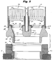
- the lower inlet nozzle portion 52 of each lower tie plate 50 is circular in shape, and is seated within a corresponding opening 54 in the inter-bundle support plate 40.
- each plate 40 is provided with four such openings 54 to accommodate the lower tie plates of the four sub-fuel bundles supported on each plate 40.
- Plate 40 is otherwise of generally square shape and of a cross sectional size similar to the large channel 16.
- the four openings 54 in plate 40 each taper downwardly and inwardly along surfaces 56 such that the vertical centerlines of the openings 54 are offset relative to the vertical centerline of a common inlet opening 62, such that coolant flow is caused to change direction as it flows upwardly through the plate 40 into the individual sub-fuel bundles 26.
- a common inlet opening 62 as defined by the mounting sleeve portion 65 of the plate 40 supplies liquid coolant to the four openings 54.
- This sleeve portion 64 is formed exteriorly with a tapered annular seating surface at 66 and a horizontally oriented seating flange 68 which engages complementary surfaces 70, 72, respectively, on the support cup 42, fixed to the core plate P and seated within the plate P in a similar manner.
- the openings 54 of the support plate 40 are surrounded by tapered seating surfaces 74 and a horizontal top surface 76 upon which mating surfaces 78, 80, respectively, of the lower tie plates 50 are seated.
- the large channel 16 is received over the upper edge 82 of peripheral side wall 84 of the support plate 40, as best seen in Figure 4.
- the top of the support plate is also formed with a cruciform groove or slot 86 which receives the inner channels or cross ties 18, 20, 22 and 24 and through which coolant is supplied via ports 30 ( Figure 2).
- the entire sub-fuel bundle assembly 14 including channel 16 and four sub-fuel bundle assemblies 26 can be lifted from the support cup 44 (as shown in Figure 5) during refuel or repair procedures.
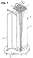
- FIG. 7-11 a second embodiment of the invention is illustrated wherein a homogeneous type bundle approach is employed.
- like reference numerals, but with the prefix "1" added are used to designate components corresponding to those in the first described embodiment.
- a prime (') is used for corresponding alpha characters.
- the homgeneous type bundle 114 no water cross 28 is provided between the individual sub-fuel bundles 126 within the large channel 116. Rather, a pair of mutually perpendicular, vented partitions 118, 120 (which may be welded together as a cruciform unit prior to insertion within the channel 116) are utilized between the sub-fuel bundles 126 to provide structural support to the channel.
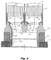
- the vented partitions 118, 120 divide the bundle into four quadrants A', B', C' and D', no water cross is provided. Rather, the partitions 118, 120 are each formed with flow communication holes (preferably in the form of a regular array or pattern of holes 92 (see Figure 9) along the entire length of each partition 118 and 120 in the nature of a perforated sheet) to provide pressure equalization among the sub-fuel bundles 126 and thus assure good stability characteristics. These cross ties or partitions 118, 120 also assure good critical power ratio margin for the large bundle, based on availability of thermal analysis basis data.
- a cruciform groove or slot 186 is provided in the support plate 140 for the vented partitions 118, 120. Otherwise, the construction of the plate 140 and support cup 144 is similar to that previously described in connection with the first embodiment.
Landscapes
- Physics & Mathematics (AREA)
- Engineering & Computer Science (AREA)
- Plasma & Fusion (AREA)
- General Engineering & Computer Science (AREA)
- High Energy & Nuclear Physics (AREA)
- Fuel Cell (AREA)
- Monitoring And Testing Of Nuclear Reactors (AREA)
Applications Claiming Priority (2)
| Application Number | Priority Date | Filing Date | Title |
|---|---|---|---|
| US348155 | 1994-11-28 | ||
| US08/348,155 US5519746A (en) | 1994-11-28 | 1994-11-28 | Large BWR fuel channel design |
Publications (2)
| Publication Number | Publication Date |
|---|---|
| EP0716422A1 true EP0716422A1 (fr) | 1996-06-12 |
| EP0716422B1 EP0716422B1 (fr) | 2001-10-04 |
Family
ID=23366855
Family Applications (1)
| Application Number | Title | Priority Date | Filing Date |
|---|---|---|---|
| EP95307863A Expired - Lifetime EP0716422B1 (fr) | 1994-11-28 | 1995-11-03 | Assemblage des crayons de combustible d'un réacteur nucléaire à eau bouillante avec répartition en quatre sous-assemblages et comprenant un canal |
Country Status (4)
| Country | Link |
|---|---|
| US (1) | US5519746A (fr) |
| EP (1) | EP0716422B1 (fr) |
| JP (1) | JPH08254589A (fr) |
| DE (1) | DE69523021T2 (fr) |
Families Citing this family (17)
| Publication number | Priority date | Publication date | Assignee | Title |
|---|---|---|---|---|
| US6097779A (en) * | 1998-02-17 | 2000-08-01 | General Electric Company | Fuel bundle and control rod assembly for a nuclear reactor |
| JP3788045B2 (ja) * | 1998-07-01 | 2006-06-21 | 株式会社日立製作所 | 燃料集合体 |
| DE60126709T2 (de) * | 2000-06-20 | 2007-10-25 | General Electric Co. | Kernkonfiguration für einen Kernreaktor |
| US6813327B1 (en) * | 2000-10-19 | 2004-11-02 | General Electric Company | Core support for an F-lattice core of a boiling water nuclear reactor |
| US7424412B2 (en) * | 2002-12-23 | 2008-09-09 | Global Nuclear Fuel - Americas, Llc | Method of determining nuclear reactor core design with reduced control blade density |
| US20050069079A1 (en) * | 2003-09-12 | 2005-03-31 | Boardman Charles Edward | Modular reactor containment system |
| US7463711B1 (en) | 2004-05-25 | 2008-12-09 | Areva Np Inc. | Fuel channel fastener |
| US7577230B2 (en) * | 2006-12-22 | 2009-08-18 | Global Nuclear Fuel-Americas, Llc | Fuel support and method for modifying coolant flow in a nuclear reactor |
| UA98370C2 (ru) | 2007-12-26 | 2012-05-10 | Ториум Пауэр Инк. | Ядерный реактор (варианты), топливная сборка из зажигающе-воспроизводящих модулей для ядерного реактора (варианты) и топливный элемент топливной сборки |
| US8116423B2 (en) | 2007-12-26 | 2012-02-14 | Thorium Power, Inc. | Nuclear reactor (alternatives), fuel assembly of seed-blanket subassemblies for nuclear reactor (alternatives), and fuel element for fuel assembly |
| JP5755568B2 (ja) | 2008-12-25 | 2015-07-29 | トリウム・パワー、インクThorium Power,Inc. | 軽水炉核燃料集合体および軽水炉 |
| EP2306464B1 (fr) * | 2009-09-30 | 2013-07-24 | Areva NP | Module destiné à former un assemblage de combustible nucléaire et assemblage de combustible nucléaire constitué de tels modules |
| US10170207B2 (en) | 2013-05-10 | 2019-01-01 | Thorium Power, Inc. | Fuel assembly |
| US10192644B2 (en) | 2010-05-11 | 2019-01-29 | Lightbridge Corporation | Fuel assembly |
| WO2011143172A1 (fr) | 2010-05-11 | 2011-11-17 | Thorium Power, Inc. | Assemblage de combustible à noyau d'alliage de combustibles métalliques et son procédé de fabrication |
| US9287012B2 (en) | 2010-07-25 | 2016-03-15 | Global Nuclear Fuel—Americas, LLC | Optimized fuel assembly channels and methods of creating the same |
| JP7403437B2 (ja) * | 2020-12-18 | 2023-12-22 | 日立Geニュークリア・エナジー株式会社 | 沸騰水型原子炉における燃料集合体の下部取り合い構造 |
Citations (6)
| Publication number | Priority date | Publication date | Assignee | Title |
|---|---|---|---|---|
| US3929565A (en) * | 1971-02-03 | 1975-12-30 | Asea Atom Ab | Nuclear reactor with groups of elongated absorber units carried by control rods |
| EP0050837A1 (fr) * | 1980-10-29 | 1982-05-05 | Ab Asea-Atom | Faisceau d'éléments combustibles pour un réacteur nucléaire |
| DE3427372A1 (de) * | 1983-08-04 | 1985-02-21 | Aktiebolaget Asea-Atom, Västeraas | Brennelementbuegel fuer einen siedewasserreaktor |
| JPH04296693A (ja) * | 1991-03-26 | 1992-10-21 | Toshiba Corp | 原子炉の炉心 |
| DE4117622A1 (de) * | 1991-05-29 | 1992-12-03 | Siemens Ag | Kerngitterstruktur fuer kernreaktoren, insbesondere fuer heizreaktoren |
| DE4423128A1 (de) * | 1993-07-05 | 1995-01-26 | Asea Atom Ab | Reaktorkern für einen Siedewasserkernreaktor |
Family Cites Families (18)
| Publication number | Priority date | Publication date | Assignee | Title |
|---|---|---|---|---|
| JPS51140090A (en) * | 1975-05-30 | 1976-12-02 | Hitachi Ltd | Fuel aggregate |
| SE420545B (sv) * | 1979-07-03 | 1981-10-12 | Asea Atom Ab | Brenslepatron for en kokarreaktor |
| SE423760B (sv) * | 1980-11-05 | 1982-05-24 | Asea Atom Ab | Kernbrenslepatron |
| SE424931B (sv) * | 1980-12-19 | 1982-08-16 | Asea Atom Ab | Brenslepatron med vattenfordelningsrenna |
| SE433986B (sv) * | 1982-07-12 | 1984-06-25 | Asea Atom Ab | Kernbrenslepatron |
| SE445500B (sv) * | 1984-11-12 | 1986-06-23 | Asea Atom Ab | Brenslepatron |
| US4659543A (en) * | 1984-11-16 | 1987-04-21 | Westinghouse Electric Corp. | Cross brace for stiffening a water cross in a fuel assembly |
| SE450177B (sv) * | 1985-10-16 | 1987-06-09 | Asea Atom Ab | Kernbrenslepatron |
| US4753774A (en) * | 1986-02-06 | 1988-06-28 | Westinghouse Electric Corp. | Orificing of water cross inlet in BWR fuel assembly |
| SE454822B (sv) * | 1986-04-29 | 1988-05-30 | Asea Atom Ab | Kernbrenslepatron till en kernreaktor |
| US4740350A (en) * | 1986-07-22 | 1988-04-26 | Westinghouse Electric Corp. | BWR fuel assembly having fuel rod spacers axially positioned by exterior springs |
| US4759912A (en) * | 1986-12-09 | 1988-07-26 | Westinghouse Electric Corp. | BWR fuel assembly having hybrid fuel design |
| EP0307705A1 (fr) * | 1987-09-10 | 1989-03-22 | Siemens Aktiengesellschaft | Assemblage de combustible de réacteur nucléaire |
| SE464995B (sv) * | 1989-11-14 | 1991-07-08 | Asea Atom Ab | Braenslepatron foer en kokarreaktor |
| SE464993B (sv) * | 1989-11-14 | 1991-07-08 | Asea Atom Ab | Braenslepatron foer en kokarreaktor |
| SE464994B (sv) * | 1989-11-14 | 1991-07-08 | Asea Atom Ab | Braenslepatron foer en kokarreaktor |
| JPH04299283A (ja) * | 1991-03-28 | 1992-10-22 | Toshiba Corp | 原子炉の燃料集合体 |
| JP3055820B2 (ja) * | 1991-07-05 | 2000-06-26 | 株式会社東芝 | 燃料集合体と炉心 |
-
1994
- 1994-11-28 US US08/348,155 patent/US5519746A/en not_active Expired - Fee Related
-
1995
- 1995-11-03 DE DE69523021T patent/DE69523021T2/de not_active Expired - Fee Related
- 1995-11-03 EP EP95307863A patent/EP0716422B1/fr not_active Expired - Lifetime
- 1995-11-24 JP JP7305294A patent/JPH08254589A/ja active Pending
Patent Citations (6)
| Publication number | Priority date | Publication date | Assignee | Title |
|---|---|---|---|---|
| US3929565A (en) * | 1971-02-03 | 1975-12-30 | Asea Atom Ab | Nuclear reactor with groups of elongated absorber units carried by control rods |
| EP0050837A1 (fr) * | 1980-10-29 | 1982-05-05 | Ab Asea-Atom | Faisceau d'éléments combustibles pour un réacteur nucléaire |
| DE3427372A1 (de) * | 1983-08-04 | 1985-02-21 | Aktiebolaget Asea-Atom, Västeraas | Brennelementbuegel fuer einen siedewasserreaktor |
| JPH04296693A (ja) * | 1991-03-26 | 1992-10-21 | Toshiba Corp | 原子炉の炉心 |
| DE4117622A1 (de) * | 1991-05-29 | 1992-12-03 | Siemens Ag | Kerngitterstruktur fuer kernreaktoren, insbesondere fuer heizreaktoren |
| DE4423128A1 (de) * | 1993-07-05 | 1995-01-26 | Asea Atom Ab | Reaktorkern für einen Siedewasserkernreaktor |
Non-Patent Citations (1)
| Title |
|---|
| PATENT ABSTRACTS OF JAPAN vol. 017, no. 107 (P - 1496) 4 March 1993 (1993-03-04) * |
Also Published As
| Publication number | Publication date |
|---|---|
| JPH08254589A (ja) | 1996-10-01 |
| US5519746A (en) | 1996-05-21 |
| EP0716422B1 (fr) | 2001-10-04 |
| DE69523021T2 (de) | 2002-06-06 |
| DE69523021D1 (de) | 2001-11-08 |
Similar Documents
| Publication | Publication Date | Title |
|---|---|---|
| US5519746A (en) | Large BWR fuel channel design | |
| EP0146896B1 (fr) | Grille d'espacement partielle pour assemblage combustible d'un réacteur nucléaire | |
| US8102961B2 (en) | Control rod guide tube and method for providing coolant to a nuclear reactor fuel assembly | |
| JP2503026B2 (ja) | 燃料集合体用のフロ―ミキシング中間格子 | |
| EP0406637B1 (fr) | Installation d'un réacteur à eau bouillante à réduction diphasique de suppression de pression | |
| US6510192B1 (en) | Boiling water type nuclear reactor core and operation method thereof | |
| US6934350B1 (en) | Core configuration for a nuclear reactor | |
| EP0260601B1 (fr) | Grille d'espacement des aiguilles de combustible ayant des moyens de déflection pour le courant du réfrigérant liquide | |
| EP0751527B1 (fr) | Assemblage combustible pour un réacteur nucléaire à eau bouillante dont l'écartement des crayons combustibles est variable | |
| US4970048A (en) | Mixing grid with fins for nuclear fuel assembly | |
| US4957698A (en) | Advanced boiling water reactor fuel assembly design | |
| US4683117A (en) | Nuclear fuel assembly incorporating primary and secondary structural support members | |
| US20010014135A1 (en) | Nuclear fuel assembly | |
| JPS62184389A (ja) | 原子炉燃料集合体の燃料棒 | |
| US4738819A (en) | Boiling water nuclear reactor fuel assembly with cross-flow elimination at upper spacer locations | |
| US5859886A (en) | Fuel assembly for a boiling water reactor | |
| EP1202289B1 (fr) | Structure de support pour un coeur à réseau F d'un réacteur nucléaire à eau bouillante | |
| EP0193923B1 (fr) | Construction d'un assemblage combustible universel pour un réacteur nucléaire | |
| CA1097443A (fr) | Systeme de positionnement peripherique d'assemblages d'elements combustibles par faisceaux en forme d'aiguilles | |
| EP0526777B1 (fr) | Assemblage de combustible d'un réacteur à eau bouillante muni de tubes à eau | |
| EP0200111B1 (fr) | Assemblage combustible pour réacteur nucléaire à eau bouillante | |
| US6259756B1 (en) | Control blade sequence patterns for optimization of BWR power control | |
| EP0514215B1 (fr) | Emplacement des barreaux à longeurs partielles dans un assemblage de combustible du type réacteur à eau bouillante pour contrÔler la réactivité | |
| EP1168370B1 (fr) | Configuration du coeur d'un réacteur nucléaire | |
| JPS6118888A (ja) | 燃料集合体及び原子炉の炉心構造 |
Legal Events
| Date | Code | Title | Description |
|---|---|---|---|
| PUAI | Public reference made under article 153(3) epc to a published international application that has entered the european phase |
Free format text: ORIGINAL CODE: 0009012 |
|
| AK | Designated contracting states |
Kind code of ref document: A1 Designated state(s): CH DE IT LI NL SE |
|
| 17P | Request for examination filed |
Effective date: 19961212 |
|
| 17Q | First examination report despatched |
Effective date: 19970909 |
|
| GRAG | Despatch of communication of intention to grant |
Free format text: ORIGINAL CODE: EPIDOS AGRA |
|
| GRAG | Despatch of communication of intention to grant |
Free format text: ORIGINAL CODE: EPIDOS AGRA |
|
| GRAH | Despatch of communication of intention to grant a patent |
Free format text: ORIGINAL CODE: EPIDOS IGRA |
|
| GRAH | Despatch of communication of intention to grant a patent |
Free format text: ORIGINAL CODE: EPIDOS IGRA |
|
| GRAA | (expected) grant |
Free format text: ORIGINAL CODE: 0009210 |
|
| AK | Designated contracting states |
Kind code of ref document: B1 Designated state(s): CH DE IT LI NL SE |
|
| REG | Reference to a national code |
Ref country code: CH Ref legal event code: NV Representative=s name: RITSCHER & SEIFERT Ref country code: CH Ref legal event code: EP |
|
| REF | Corresponds to: |
Ref document number: 69523021 Country of ref document: DE Date of ref document: 20011108 |
|
| PLBE | No opposition filed within time limit |
Free format text: ORIGINAL CODE: 0009261 |
|
| STAA | Information on the status of an ep patent application or granted ep patent |
Free format text: STATUS: NO OPPOSITION FILED WITHIN TIME LIMIT |
|
| 26N | No opposition filed | ||
| PGFP | Annual fee paid to national office [announced via postgrant information from national office to epo] |
Ref country code: SE Payment date: 20021018 Year of fee payment: 8 |
|
| PGFP | Annual fee paid to national office [announced via postgrant information from national office to epo] |
Ref country code: NL Payment date: 20021021 Year of fee payment: 8 Ref country code: CH Payment date: 20021021 Year of fee payment: 8 |
|
| PG25 | Lapsed in a contracting state [announced via postgrant information from national office to epo] |
Ref country code: SE Free format text: LAPSE BECAUSE OF NON-PAYMENT OF DUE FEES Effective date: 20031104 |
|
| PG25 | Lapsed in a contracting state [announced via postgrant information from national office to epo] |
Ref country code: LI Free format text: LAPSE BECAUSE OF NON-PAYMENT OF DUE FEES Effective date: 20031130 Ref country code: CH Free format text: LAPSE BECAUSE OF NON-PAYMENT OF DUE FEES Effective date: 20031130 |
|
| PG25 | Lapsed in a contracting state [announced via postgrant information from national office to epo] |
Ref country code: NL Free format text: LAPSE BECAUSE OF NON-PAYMENT OF DUE FEES Effective date: 20040601 |
|
| EUG | Se: european patent has lapsed | ||
| REG | Reference to a national code |
Ref country code: CH Ref legal event code: PL |
|
| NLV4 | Nl: lapsed or anulled due to non-payment of the annual fee |
Effective date: 20040601 |
|
| PG25 | Lapsed in a contracting state [announced via postgrant information from national office to epo] |
Ref country code: IT Free format text: LAPSE BECAUSE OF NON-PAYMENT OF DUE FEES;WARNING: LAPSES OF ITALIAN PATENTS WITH EFFECTIVE DATE BEFORE 2007 MAY HAVE OCCURRED AT ANY TIME BEFORE 2007. THE CORRECT EFFECTIVE DATE MAY BE DIFFERENT FROM THE ONE RECORDED. Effective date: 20051103 |
|
| PGFP | Annual fee paid to national office [announced via postgrant information from national office to epo] |
Ref country code: DE Payment date: 20071221 Year of fee payment: 13 |
|
| PG25 | Lapsed in a contracting state [announced via postgrant information from national office to epo] |
Ref country code: DE Free format text: LAPSE BECAUSE OF NON-PAYMENT OF DUE FEES Effective date: 20090603 |