EP0716522A2 - Hybrider Ring mit Wellenlängenmultiplex geeignet für die Anwendung in regionalen Netzwerken - Google Patents
Hybrider Ring mit Wellenlängenmultiplex geeignet für die Anwendung in regionalen Netzwerken Download PDFInfo
- Publication number
- EP0716522A2 EP0716522A2 EP95308760A EP95308760A EP0716522A2 EP 0716522 A2 EP0716522 A2 EP 0716522A2 EP 95308760 A EP95308760 A EP 95308760A EP 95308760 A EP95308760 A EP 95308760A EP 0716522 A2 EP0716522 A2 EP 0716522A2
- Authority
- EP
- European Patent Office
- Prior art keywords
- telecommunications
- telecommunications network
- add
- optical
- branching unit
- Prior art date
- Legal status (The legal status is an assumption and is not a legal conclusion. Google has not performed a legal analysis and makes no representation as to the accuracy of the status listed.)
- Withdrawn
Links
- 230000003287 optical effect Effects 0.000 claims abstract description 32
- 239000013307 optical fiber Substances 0.000 claims abstract description 32
- 238000004891 communication Methods 0.000 description 20
- 239000000835 fiber Substances 0.000 description 12
- 230000005540 biological transmission Effects 0.000 description 4
- 238000010586 diagram Methods 0.000 description 4
- 238000009826 distribution Methods 0.000 description 4
- 230000001360 synchronised effect Effects 0.000 description 3
- 230000002457 bidirectional effect Effects 0.000 description 2
- 229910052691 Erbium Inorganic materials 0.000 description 1
- 239000004020 conductor Substances 0.000 description 1
- 238000007796 conventional method Methods 0.000 description 1
- 230000006866 deterioration Effects 0.000 description 1
- 239000006185 dispersion Substances 0.000 description 1
- 230000000694 effects Effects 0.000 description 1
- UYAHIZSMUZPPFV-UHFFFAOYSA-N erbium Chemical compound [Er] UYAHIZSMUZPPFV-UHFFFAOYSA-N 0.000 description 1
- 230000036039 immunity Effects 0.000 description 1
- 238000002955 isolation Methods 0.000 description 1
- 238000013507 mapping Methods 0.000 description 1
- 238000000034 method Methods 0.000 description 1
- 238000012986 modification Methods 0.000 description 1
- 230000004048 modification Effects 0.000 description 1
- 230000006855 networking Effects 0.000 description 1
- 229910052761 rare earth metal Inorganic materials 0.000 description 1
Images


Classifications
-
- H—ELECTRICITY
- H04—ELECTRIC COMMUNICATION TECHNIQUE
- H04J—MULTIPLEX COMMUNICATION
- H04J14/00—Optical multiplex systems
- H04J14/02—Wavelength-division multiplex systems
- H04J14/0278—WDM optical network architectures
- H04J14/028—WDM bus architectures
-
- H—ELECTRICITY
- H04—ELECTRIC COMMUNICATION TECHNIQUE
- H04L—TRANSMISSION OF DIGITAL INFORMATION, e.g. TELEGRAPHIC COMMUNICATION
- H04L12/00—Data switching networks
- H04L12/28—Data switching networks characterised by path configuration, e.g. LAN [Local Area Networks] or WAN [Wide Area Networks]
-
- H—ELECTRICITY
- H04—ELECTRIC COMMUNICATION TECHNIQUE
- H04J—MULTIPLEX COMMUNICATION
- H04J14/00—Optical multiplex systems
- H04J14/02—Wavelength-division multiplex systems
- H04J14/0227—Operation, administration, maintenance or provisioning [OAMP] of WDM networks, e.g. media access, routing or wavelength allocation
- H04J14/0241—Wavelength allocation for communications one-to-one, e.g. unicasting wavelengths
-
- H—ELECTRICITY
- H04—ELECTRIC COMMUNICATION TECHNIQUE
- H04J—MULTIPLEX COMMUNICATION
- H04J14/00—Optical multiplex systems
- H04J14/02—Wavelength-division multiplex systems
- H04J14/0278—WDM optical network architectures
- H04J14/0283—WDM ring architectures
-
- H—ELECTRICITY
- H04—ELECTRIC COMMUNICATION TECHNIQUE
- H04J—MULTIPLEX COMMUNICATION
- H04J14/00—Optical multiplex systems
- H04J14/02—Wavelength-division multiplex systems
- H04J14/0278—WDM optical network architectures
- H04J14/0286—WDM hierarchical architectures
Definitions
- This invention relates to the ring networks. More particularly, this invention relates to a wavelength division multiplexed hybrid ring suitable for use in regional area networks.
- the global fiber optic telecommunications network has been growing rapidly due . in part, to the superior quality of service and high capacity such networks provide. It is estimated that more than 60 countries are presently connected to the global fiber optic network and, by the turn of the century, this number will grow to more than 100. However, there are still many large regions of the globe that are unable to receive the benefits that global communications connectivity brings due, for example, to lack of infrastructure, geographic isolation, and other technical impediments. Moreover, telecommunications may also be limited in the region itself. Although such regions could employ, or may already employ, distributed local area or wide area networks (LANs and WANs, respectively), it is often economically infeasible to provide reliable connectivity among such distributed networks, and connectivity to the present global fiber optic network.
- LANs and WANs distributed local area or wide area networks
- Compatibility among divergent network protocols in such a scheme is one example of the connectivity challenge. Furthermore, it is generally imprudent to rely on a series of interconnected LANs and WANs to facilitate the desired regional and global telecommunications capability since unreliable or inefficient operations in a single one of the local networks has the potential to negatively influence the telecommunications performance of the entire region. It is therefore an object of the invention to effect a fiber optic telecommunication network that is suitable for application in regional area networks.
- Such a fiber optic telecommunications network would be desirable for such a fiber optic telecommunications network to have: immunity from problems at the local level; high reliability and fault tolerance; full connectivity to the global fiber optic telecommunications network and/or other networks; flexibility in communications traffic control and routing; high capacity and capability for provision of broadband services; and, future expandability.
- a wavelength division multiplexed hybrid ring formed from a plurality of telecommunications links that connect a plurality of switching nodes.
- each telecommunications link comprising: at least one optical fiber adapted for transporting a plurality of wavelength division multiplexed channels. wherein each of the plurality of optical channels is defined by a different wavelength: and at least one branching unit disposed along the at least one optical fiber, wherein the at least one branching unit includes at least one add-drop multiplexer for adding and dropping predetermined ones of the plurality of optical channels to and from a terminal coupled to the branching unit, and the branching unit is adapted to pass predetermined ones of the plurality of optical channels between the plurality of switching nodes.
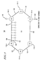
- FIG. 1 is a simplified block diagram of an illustrative example of a hybrid ring network 100, in accordance with the invention.
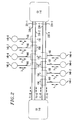
- FIG. 2 is a simplified diagram showing details of a telecommunications link used in the hybrid ring shown in FIG. 1, in accordance with the invention.
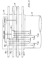
- FIG. 3 illustrates details of branching units which are utilized in the ring transmission shown in FIG. 1, in accordance with the invention.
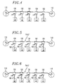
- FIGs. 4, 5, and 6 illustrate power configuration states for branching units 150 under various conditions, in accordance with the invention.
- FIG. 7 shows the traffic paths in the hybrid ring network shown in FIG. 1, in accordance with the invention.
- FIG. 8 illustrates fault tolerance in a hybrid ring network, in accordance with the invention.
- FIG. 1 is a simplified block diagram of an illustrative example of a hybrid ring network 100, in accordance with the invention.
- Hybrid ring network 100 may be used. for example, to implement a regional area telecommunications network.
- the term "region" as used herein is intended to refer to a geographic area for which telecommunications capability is desired. Typically, a region is a large area such as city or even a continent. however, the principles of the invention may also be readily applied to geographic areas served by relatively small LANs, for example, an office building.
- Hybrid ring network 100 includes a plurality of switching nodes, which may be, for example, central offices (“COs") 110. COs 110 are arranged in a ring around region 102, as shown.
- COs central offices
- COs are known in the art and perform a full range of communications traffic networking, for example mapping and switching, according to conventional methods.
- COs 110 are contemplated to include, for example, optical interfaces, transmission equipment, multiplexing equipment, cross-connect equipment, and switches, such as a 4ESS or 5ESS central office switches produced by AT&T. All such devices are known. It is noted that COs 110 may connect other telecommunication offices via transmission facilities that are typically utilized in the art.
- Hybrid ring network 100 may carry traffic unidirectionally or bidirectionally. In this illustrative example, six COs 110 are shown, however, it is contemplated that any number of COs could readily be utilized in applications of the invention.
- COs in hybrid ring network 100 advantageously allows full connectivity and compatibility with other networks external to the ring, including the global fiber optic network. These other networks could include local area, metropolitan area, and wide area networks, as well as public switched telephone networks.
- An exemplary external connection is represented by reference numeral 103, couples as shown to CO 110-4 in FIG. 1. Such an external connection may include an optical fiber, or telecommunications link 130, as described below.
- COs 110 may be coupled using, for example, telecommunications links 130 as shown.
- FIG. 2 is a simplified diagram showing details of telecommunications link 130.
- Each telecommunications link 130 includes a plurality of conventional optical fibers 220, as shown in FIG. 2.
- Optical fibers 220 could be, for example, dispersion shifted, single mode optical fibers.
- Optical fibers 220 in telecommunications link 130 may be collected in a conventional cable arrangement (not shown).
- Telecommunications links 130 may be physically deployed on land, undersea, or in combinations thereof.
- Telecommunications links 130 may additionally include integrated optical repeaters, such as fiber amplifiers, or regenerators (not shown) or be repeaterless.
- hybrid ring network 100 employs a series of concatenated fiber amplifiers in each telecommunications link 130.
- Fiber amplifiers may be, for example, optical fibers which are doped with rare earth elements such as erbium.
- Telecommunications link 130 includes, in this illustrative example, four optical fibers 220, which are arranged in two bidirectional optical fiber pairs 221-1 and 221-2. However, it may desirable in some applications of the invention to use other than four optical fibers to connect the COs, for example, eight optical fibers, or use other arrangements of optical fiber pairs.
- a plurality of terminals which are typically used to provide telecommunications service connections to localities within the region.
- the term "locality" as used herein, for example, may refer to a country in a continent, as well as to a suite in an office complex.
- the terminals are shown as cable stations 140 as shown. Cable stations 140 may be termination points for communications traffic being transported in hybrid ring network 100, or may be used as switching node connections to locally deployed LANs and WANs, if desired.
- communications traffic being transported in hybrid ring network 100 may be digital signal in accordance with International Telecommunications Union Synchronous Digital Hierarchy (“SDH”) digital signal formats, including Synchronous Transport Module level 1 (“STM-1”) digital signals and Synchronous Transport Module level 16 (STM-16) digital signals.
- SDH International Telecommunications Union Synchronous Digital Hierarchy
- STM-1 Synchronous Transport Module level 1
- STM-16 Synchronous Transport Module level 16
- Each cable station 140 is coupled to telecommunications link 130 using one of a plurality of branching units 150 and one of a plurality of branch cables 160, as shown.
- Branch cables 160 may include optical repeaters or regenerators, or be repeaterless.
- eight cable stations 140 are shown coupled to a single exemplary telecommunications link 130, however, arrangements of any number of cable stations coupled to one or more telecommunications links 130 are contemplated to fall within the spirit and scope of the invention.
- the actual number of cable stations used in applications of the invention will depend on the number of optical fibers and wavelengths available. It is also intended that additional cable stations 140 may be coupled to COs 110 directly. This aspect of the invention is illustrated in FIG.
- hybrid ring network 100 may take on a number of different network topologies, including for example, complete rings, partial rings, busses, or combinations thereof.
- FIG. 2 also illustrates operation aspects of the hybrid ring network 100 shown in FIG. 1, in accordance with the invention.
- telecommunications links 130 carry a plurality of wavelength division multiplexed optical signals.
- Each optical fiber 220 then, carries a plurality of optical channels, where each channel is defined by a different wavelength ⁇ N .
- the wavelengths are conveniently numbered from 1 to N from lowest to highest wavelength.
- each optical fiber pair 221 uses the same wavelengths 1 to N, resulting in a total 2N optical channels.
- other values for N may also be used.
- the eight wavelengths are functionally distributed into local or express wavelengths.
- the local wavelengths within a particular telecommunications link 130 carry communications traffic between COs 110 and cable stations 140.
- the express wavelengths directly carry communications traffic between COs 110 without communications connectivity to cable stations 140.
- four wavelengths are used for local and four wavelengths for express on each fiber optic pair, for a total of eight local wavelengths and eight express wavelengths in each telecommunications link 130.
- other distributions may be desirable in certain applications of the invention.
- the ratio of express to local wavelengths may vary in proportion to communication traffic loading and utilization conditions. Such variation may also occur between telecommunications links 130, that is, the ratio between local and express wavelengths may vary from telecommunications link to telecommunications link.
- telecommunications links 130 that is, the ratio between local and express wavelengths may vary from telecommunications link to telecommunications link.
- This excess bandwidth can be distributed to the telecommunications links 130 as additional local or express wavelengths, or reserved for future network expansion.
- the functional distribution between local and express wavelengths described above provides a high degree of flexibility in communications traffic control and routing in hybrid ring network 100 which may be particularly desirable in certain applications of the invention.
- Branching units 150 are utilized to selectively add and drop communications traffic to and from cable stations 140.
- a particular local wavelength is associated with only one cable station 140 on each optical fiber pair.
- ⁇ 1 is assigned to cable station 140-1
- ⁇ 2 is assigned to cable station 140-2
- ⁇ 3 is assigned to cable station 140-3
- ⁇ 4 is assigned to cable station 140-4 on optical fiber pair 221-1.
- ⁇ 1 is assigned to cable station 140-5
- ⁇ 2 is assigned to cable station 140-6
- ⁇ 3 is assigned to cable station 140-7
- ⁇ 4 is assigned to cable station 140-8.
- each telecommunications link 130 to achieve a regional area telecommunications network. Accordingly, those skilled in the art will appreciate that the same wavelengths ⁇ N are used in the other optical spans 130. Furthermore, the association of a particular local wavelength to only one particular cable station 140 advantageously limits the cable station's ability to negatively affect the operation of the entire hybrid ring network 100 should local conditions cause a deterioration in the performance of that particular cable station. Moreover, this advantageous limitation on the local cable station may be further enhanced, in certain applications of the invention, by locating telecommunications links 130 and cable stations 140 in a physically distant location, for example, underseas if warranted.
- branching units 150 include a plurality of add-drop multiplexers 300 which are coupled to telecommunications link 130 including optical fibers 220, and controller 310.
- Add-drop multiplexer 300-1 is coupled to optical fiber 220-1.
- Add-drop multiplexer 300-2 is coupled to optical fiber 220-2.
- Controller 310 is coupled, as shown, to each add-drop multiplexers 300.
- Controller 310 is also coupled to power conductor 370 to control the power conduction to the optical repeaters which are utilized in this illustrative example.
- Add-drop multiplexers 300 could comprise, for example, Fabry-Perot gratings, Bragg gratings, couplers and splitters which are well known. Alternatively, add-drop multiplexers 300 may comprise optical channel dropping filters with integrated transceivers as described in United States patent application serial number 08/152,517, the disclosure of which is incorporated by reference herein.
- Add-drop multiplexers may also comprise optical channel adding/dropping filters as described in United States patent application serial number 08/184,165, the disclosure of which is incorporated by reference herein Add-drop multiplexers may also comprise fast tunable channel dropping filters as described in United States patent application serial number 08/153,523, the disclosure of which is incorporated by reference herein.
- Add-drop multiplexers 300 are tuned to selectively add and drop communications traffic at the desired wavelength as discussed above, for example, in response to control signals from controller 310.
- Controller 310 may also be used to control the power distribution in repeatered applications, for example, undersea applications. It should be noted that controller 310 is optionally utilized for wavelength selection, however, it is preferably used for power distribution by controlling the power configurations states for branching units 150. Controller 310 may be a conventional programmable microprocessor. for example. It may desirable in some applications of the invention to centrally control the operation of all controllers 310 in branching units 150.
- FIGs. 4, 5, and 6 illustrate power configuration states for branching units 150 under various conditions, in accordance with the invention.
- FIG. 4 illustrates a normal state of operation for one exemplary telecommunications link 130 (FIG. 1), when no faults exist. As shown, the telecommunications link 130 is powered from CO 110 to CO 110. Branch cables 160 may be powered, if necessary, from the cable stations 140 to ground at the branching unit 150, as shown. In the event of a fault, as shown in FIG. 5, the power state is reconfigured to the state shown in FIG. 6 under control of controller 310 (FIG. 3).
- FIG. 7 shows the traffic paths in one exemplary telecommunications link 130 in the hybrid ring network 100 shown in FIG. 1, in accordance with the invention. For purposes of clarity in illustration, only four cable stations 140 are shown. FIG. 7 shows cable stations 140 having diverse traffic paths between adjacent COs 110.
- fault tolerance i.e., communications traffic restoration on the ring in the event of a fault.
- Faults could include, for example, fiber failures such as a cut, degraded signals, or equipment failures.
- the following examples are useful in illustrating this feature.
- the normal communications path between cable station 140-1 and cable station 820 passes through CO 110-4.
- a fault occurs somewhere between cable station 140-1 and CO 110-4. Communications traffic between these cable stations is rerouted on a communications path passing through cable station 140-1 to CO 110-2, around the ring to CO 110-4, and then to cable station 820.
- the fault occurs somewhere between CO 110-4 and cable station 820. In this case, communications traffic is rerouted on a communications path passing through CO 110-2, around the ring, to CO 110-M, and then to cable station 820.
- a hybrid ring network is herein achieved, in accordance with the principles of the invention, that incorporates both line and path switching.
- line switching occurs between cable stations and COs, while path switching occurs between COs.
- path switching occurs between COs.
- Table 1 below presents some typical specifications for hybrid ring network 100 shown in FIG. 1.
- TABLE 1 No of COs 8 No. of telecommunications links 8 No. of cable stations/telecommunication link 8 Total no. cable stations+COs 72 No. of optical fiber pairs/telecommunications link 2 No. of different wavelengths, N 8 No. of wavelengths/optical fiber pair 8 No. of optical channel/telecommunications link 16 Transmission rate per optical channel 2.5 Gbits/sec Total hybrid ring network capacity 40 Gbit/sec Typical telecommunications link length ⁇ 6,000 km Typical cable station to CO cable length 100-6,000 km Optical channel communications signal format SDH STM-1/STM-16 No. of uncompressed voice circuits/optical channel ⁇ 30,000
Landscapes
- Engineering & Computer Science (AREA)
- Computer Networks & Wireless Communication (AREA)
- Signal Processing (AREA)
- Optical Communication System (AREA)
- Small-Scale Networks (AREA)
Applications Claiming Priority (2)
| Application Number | Priority Date | Filing Date | Title |
|---|---|---|---|
| US35086494A | 1994-12-07 | 1994-12-07 | |
| US350864 | 1994-12-07 |
Publications (2)
| Publication Number | Publication Date |
|---|---|
| EP0716522A2 true EP0716522A2 (de) | 1996-06-12 |
| EP0716522A3 EP0716522A3 (de) | 1998-08-05 |
Family
ID=23378530
Family Applications (1)
| Application Number | Title | Priority Date | Filing Date |
|---|---|---|---|
| EP95308760A Withdrawn EP0716522A3 (de) | 1994-12-07 | 1995-12-05 | Hybrider Ring mit Wellenlängenmultiplex geeignet für die Anwendung in regionalen Netzwerken |
Country Status (7)
| Country | Link |
|---|---|
| EP (1) | EP0716522A3 (de) |
| JP (1) | JPH08237289A (de) |
| KR (1) | KR960027711A (de) |
| AU (1) | AU711802B2 (de) |
| CA (1) | CA2164356A1 (de) |
| MX (1) | MX9505067A (de) |
| TW (1) | TW302584B (de) |
Cited By (5)
| Publication number | Priority date | Publication date | Assignee | Title |
|---|---|---|---|---|
| EP0820166A3 (de) * | 1996-07-18 | 1998-12-23 | Kokusai Denshin Denwa Kabushiki Kaisha | Optisches Übertragungssystem und Vorrichtung zum optischen Abzweigen |
| RU2188512C2 (ru) * | 1996-12-06 | 2002-08-27 | Самсунг Электроникс Ко., Лтд. | Оптический фильтр длин волн и оптический демультиплексор |
| RU2199823C2 (ru) * | 2001-02-26 | 2003-02-27 | Институт систем обработки изображений РАН | Оптический мультиплексор-демультиплексор |
| KR20040052054A (ko) * | 2002-12-13 | 2004-06-19 | 주식회사 에이앤피텔레콤 | 전광섬유형 파장분할 다중화기를 이용한 광통신 방법 |
| GB2470978A (en) * | 2009-03-31 | 2010-12-15 | British Telecomm | Optical fibre network in which primary nodes are connected directly to a plurality of core nodes |
Families Citing this family (2)
| Publication number | Priority date | Publication date | Assignee | Title |
|---|---|---|---|---|
| KR100474694B1 (ko) * | 2002-10-12 | 2005-03-10 | 삼성전자주식회사 | 버스트 데이터 통신을 위한 링형 광네트워크 |
| CN119698781A (zh) * | 2022-08-19 | 2025-03-25 | 三菱电机株式会社 | 光交换装置和光交换方法 |
Family Cites Families (3)
| Publication number | Priority date | Publication date | Assignee | Title |
|---|---|---|---|---|
| US5225922A (en) * | 1991-11-21 | 1993-07-06 | At&T Bell Laboratories | Optical transmission system equalizer |
| US5440416A (en) * | 1993-02-24 | 1995-08-08 | At&T Corp. | Optical network comprising a compact wavelength-dividing component |
| CA2139957C (en) * | 1994-02-18 | 1999-02-09 | Andrew R. Chraplyvy | Multi-channel optical fiber communication system |
-
1995
- 1995-12-04 CA CA002164356A patent/CA2164356A1/en not_active Abandoned
- 1995-12-05 EP EP95308760A patent/EP0716522A3/de not_active Withdrawn
- 1995-12-05 MX MX9505067A patent/MX9505067A/es unknown
- 1995-12-05 TW TW084112949A patent/TW302584B/zh active
- 1995-12-06 JP JP7344361A patent/JPH08237289A/ja active Pending
- 1995-12-06 AU AU40274/95A patent/AU711802B2/en not_active Ceased
- 1995-12-07 KR KR1019950048508A patent/KR960027711A/ko not_active Withdrawn
Non-Patent Citations (5)
| Title |
|---|
| HILL G R: "A WAVELENGTH ROUTING APPROACH TO OPTICAL COMMUNICATIONS NETWORKS" NETWORKS: EVOLUTION OR REVOLUTION?, NEW ORLEANS, MAR. 27 - 31, 1988, no. CONF. 7, 27 March 1988, INSTITUTE OF ELECTRICAL AND ELECTRONICS ENGINEERS, pages 354-361, XP000044787 * |
| HIROSHI TAKAHASHI ET AL: "WAVELENGTH MULTIPLEXER BASED ON SIO2-TA2O5 ARRAYED-WAVEGUIDE GRATING" JOURNAL OF LIGHTWAVE TECHNOLOGY, vol. 12, no. 6, 1 June 1994, pages 989-995, XP000484216 * |
| TAKASHI NAKASHIMA ET AL: "PHOTONIC ACCESS NETWORK ARCHITECTURE" COUNTDOWN TO THE NEW MILENNIUM, PHOENIX, DEC. 2 - 5, 1991, vol. VOL. 1, no. -, 2 December 1991, INSTITUTE OF ELECTRICAL AND ELECTRONICS ENGINEERS, pages 602-606, XP000326036 * |
| THOLEY V ET AL: "DEMONSTRATION OF WDM SURVIVABLE UNIDIRECTIONAL RING NETWORK USING TUNABLE CHANNEL DROPPING RECEIVERS" ELECTRONICS LETTERS, vol. 30, no. 16, 4 August 1994, page 1323/1324 XP000471831 * |
| WAGNER S S ET AL: "MULTIWAVELENGTH RING NETWORKS FOR SWITCH CONSOLIDATION AND INTERCONNECTION" DISCOVERING A NEW WORLD OF COMMUNICATIONS, CHICAGO, JUNE 14 - 18, 1992 BOUND TOGETHER WITH B0190710, VOL. 4, vol. VOL. 3, no. -, 14 June 1992, INSTITUTE OF ELECTRICAL AND ELECTRONICS ENGINEERS, pages 1173-1179, XP000337910 * |
Cited By (5)
| Publication number | Priority date | Publication date | Assignee | Title |
|---|---|---|---|---|
| EP0820166A3 (de) * | 1996-07-18 | 1998-12-23 | Kokusai Denshin Denwa Kabushiki Kaisha | Optisches Übertragungssystem und Vorrichtung zum optischen Abzweigen |
| RU2188512C2 (ru) * | 1996-12-06 | 2002-08-27 | Самсунг Электроникс Ко., Лтд. | Оптический фильтр длин волн и оптический демультиплексор |
| RU2199823C2 (ru) * | 2001-02-26 | 2003-02-27 | Институт систем обработки изображений РАН | Оптический мультиплексор-демультиплексор |
| KR20040052054A (ko) * | 2002-12-13 | 2004-06-19 | 주식회사 에이앤피텔레콤 | 전광섬유형 파장분할 다중화기를 이용한 광통신 방법 |
| GB2470978A (en) * | 2009-03-31 | 2010-12-15 | British Telecomm | Optical fibre network in which primary nodes are connected directly to a plurality of core nodes |
Also Published As
| Publication number | Publication date |
|---|---|
| EP0716522A3 (de) | 1998-08-05 |
| JPH08237289A (ja) | 1996-09-13 |
| AU4027495A (en) | 1996-06-13 |
| KR960027711A (ko) | 1996-07-22 |
| AU711802B2 (en) | 1999-10-21 |
| CA2164356A1 (en) | 1996-06-08 |
| MX9505067A (es) | 1997-01-31 |
| TW302584B (de) | 1997-04-11 |
Similar Documents
| Publication | Publication Date | Title |
|---|---|---|
| US6587235B1 (en) | Method and apparatus for capacity-efficient restoration in an optical communication system | |
| JP3659977B2 (ja) | 存続可能な複数波長光通信ネットワーク用のリング間交差接続 | |
| Elrefaie | Multiwavelength survivable ring network architectures | |
| US6898206B2 (en) | Wavelength division multiplexed (WDM) ring passive optical network (PON) with route protection for replacement of splitter based passive optical networks | |
| US6771849B1 (en) | Optical fiber protection switch | |
| EP1360790B1 (de) | Optische übertragungssysteme mit optischen schutzsystemen, vorrichtungen und verfahren | |
| KR101396954B1 (ko) | 광 전송 장치 및 광 전송 시스템 | |
| CA2192098C (en) | Access network | |
| US7313296B2 (en) | Optical fiber protection switch | |
| AU711802B2 (en) | Wavelength division multiplexed hybrid ring suitable for use in regional area networks | |
| CA2183691C (en) | Incrementally expandable ring architecture for providing telephony services | |
| MXPA96004120A (en) | Incremental expansion ring architecture to provide telephone services | |
| JP2000115133A (ja) | 光パスクロスコネクト装置及び光ネットワーク | |
| EP1050130B1 (de) | Kommunikationssystem mit stern / ring topology | |
| WO2001077715A2 (en) | Method and apparatus for optical channel switching in an optical add/drop multiplexer | |
| WO1998033287A1 (en) | Communications system with star topology | |
| EP1045536A1 (de) | Faseroptisches kommunikationsnetzwerkgerät | |
| EP0752776B1 (de) | Netzwerkarchitektur | |
| US20060165410A1 (en) | Arrangement for avoiding node isolation in all-optical communication networks | |
| JP2003008519A (ja) | 光通信ネットワーク | |
| Clendening | Rings in a SONET network |
Legal Events
| Date | Code | Title | Description |
|---|---|---|---|
| PUAI | Public reference made under article 153(3) epc to a published international application that has entered the european phase |
Free format text: ORIGINAL CODE: 0009012 |
|
| AK | Designated contracting states |
Kind code of ref document: A2 Designated state(s): DE FR GB IT NL SE |
|
| PUAL | Search report despatched |
Free format text: ORIGINAL CODE: 0009013 |
|
| AK | Designated contracting states |
Kind code of ref document: A3 Designated state(s): DE FR GB IT NL SE |
|
| STAA | Information on the status of an ep patent application or granted ep patent |
Free format text: STATUS: THE APPLICATION IS DEEMED TO BE WITHDRAWN |
|
| 18D | Application deemed to be withdrawn |
Effective date: 19990206 |