EP0716907A1 - Dispositif de protection pour machines à outil mobile pour fendre le bois - Google Patents
Dispositif de protection pour machines à outil mobile pour fendre le bois Download PDFInfo
- Publication number
- EP0716907A1 EP0716907A1 EP95119522A EP95119522A EP0716907A1 EP 0716907 A1 EP0716907 A1 EP 0716907A1 EP 95119522 A EP95119522 A EP 95119522A EP 95119522 A EP95119522 A EP 95119522A EP 0716907 A1 EP0716907 A1 EP 0716907A1
- Authority
- EP
- European Patent Office
- Prior art keywords
- support table
- splitting
- photoelectric reflection
- photoelectric
- switches
- Prior art date
- Legal status (The legal status is an assumption and is not a legal conclusion. Google has not performed a legal analysis and makes no representation as to the accuracy of the status listed.)
- Granted
Links
- 239000002023 wood Substances 0.000 claims abstract description 18
- 230000001681 protective effect Effects 0.000 claims description 12
- 230000003287 optical effect Effects 0.000 claims description 3
- 239000010902 straw Substances 0.000 claims description 2
- 210000003127 knee Anatomy 0.000 description 3
- 208000011092 Hand injury Diseases 0.000 description 2
- 208000027418 Wounds and injury Diseases 0.000 description 2
- 230000006378 damage Effects 0.000 description 2
- 208000014674 injury Diseases 0.000 description 2
- 239000000853 adhesive Substances 0.000 description 1
- 230000001070 adhesive effect Effects 0.000 description 1
- 239000012790 adhesive layer Substances 0.000 description 1
- 238000010586 diagram Methods 0.000 description 1
- 238000006073 displacement reaction Methods 0.000 description 1
- 230000005284 excitation Effects 0.000 description 1
- 230000001788 irregular Effects 0.000 description 1
- 238000004519 manufacturing process Methods 0.000 description 1
- 238000011022 operating instruction Methods 0.000 description 1
- 230000001960 triggered effect Effects 0.000 description 1
Images
Classifications
-
- B—PERFORMING OPERATIONS; TRANSPORTING
- B27—WORKING OR PRESERVING WOOD OR SIMILAR MATERIAL; NAILING OR STAPLING MACHINES IN GENERAL
- B27L—REMOVING BARK OR VESTIGES OF BRANCHES; SPLITTING WOOD; MANUFACTURE OF VENEER, WOODEN STICKS, WOOD SHAVINGS, WOOD FIBRES OR WOOD POWDER
- B27L7/00—Arrangements for splitting wood
-
- F—MECHANICAL ENGINEERING; LIGHTING; HEATING; WEAPONS; BLASTING
- F16—ENGINEERING ELEMENTS AND UNITS; GENERAL MEASURES FOR PRODUCING AND MAINTAINING EFFECTIVE FUNCTIONING OF MACHINES OR INSTALLATIONS; THERMAL INSULATION IN GENERAL
- F16P—SAFETY DEVICES IN GENERAL; SAFETY DEVICES FOR PRESSES
- F16P3/00—Safety devices acting in conjunction with the control or operation of a machine; Control arrangements requiring the simultaneous use of two or more parts of the body
- F16P3/12—Safety devices acting in conjunction with the control or operation of a machine; Control arrangements requiring the simultaneous use of two or more parts of the body with means, e.g. feelers, which in case of the presence of a body part of a person in or near the danger zone influence the control or operation of the machine
- F16P3/14—Safety devices acting in conjunction with the control or operation of a machine; Control arrangements requiring the simultaneous use of two or more parts of the body with means, e.g. feelers, which in case of the presence of a body part of a person in or near the danger zone influence the control or operation of the machine the means being photocells or other devices sensitive without mechanical contact
- F16P3/144—Safety devices acting in conjunction with the control or operation of a machine; Control arrangements requiring the simultaneous use of two or more parts of the body with means, e.g. feelers, which in case of the presence of a body part of a person in or near the danger zone influence the control or operation of the machine the means being photocells or other devices sensitive without mechanical contact using light grids
-
- F—MECHANICAL ENGINEERING; LIGHTING; HEATING; WEAPONS; BLASTING
- F16—ENGINEERING ELEMENTS AND UNITS; GENERAL MEASURES FOR PRODUCING AND MAINTAINING EFFECTIVE FUNCTIONING OF MACHINES OR INSTALLATIONS; THERMAL INSULATION IN GENERAL
- F16P—SAFETY DEVICES IN GENERAL; SAFETY DEVICES FOR PRESSES
- F16P3/00—Safety devices acting in conjunction with the control or operation of a machine; Control arrangements requiring the simultaneous use of two or more parts of the body
- F16P3/18—Control arrangements requiring the use of both hands
- F16P3/20—Control arrangements requiring the use of both hands for electric control systems
Definitions
- the invention relates to a protective device for and on machines with moving cutting and / or splitting tools with the features of the preamble of claim 1.
- Working machines of the type mentioned are often used in agricultural and forestry operations and are often used by untrained personnel.
- the workpieces to be machined on these machines are usually manually guided into the immediate area of the moving cutting or splitting tool, or these rotating and moving tools are directly accessible by hand. Lack of attention, lack of experience and distraction of the operator lead to serious hand injuries if the hand gets into the area of the moving separating or splitting tool.
- Firewood splitting facilities are an example of this.
- a support table on which the piece of wood to be split is placed and a splitting wedge that can be moved against this support table, which is attached to an axially displaceable, so-called split tower and protrudes forward from it.
- a hydraulic piston-cylinder unit is mounted, which is fixed on the one hand on the machine frame of the device and on the other hand on the split tower.
- a motor-driven oil pump is provided, as well as a hydraulic control valve that can be operated by the operator using a lever, usually with the foot or knee. In its starting position, the riving knife is located above the table.
- the photoelectric reflection switches provided here according to the invention are a component emitting a light beam with a built-in receiving part, the emitted light beam then being one Triggers a switching pulse when it is reflected and subsequently received by the built-in receiver.
- Such photoelectric reflection switches are commercially available, for example from Sick - Optik Elektronik. These reflection switches emit a light beam, and when this emitted light beam is reflected and hits the emitting switch again, this switch is activated.
- the photoelectric reflection switches are releasably attached to the support table or to a feed device for the workpiece and / or can be folded or swung into recesses provided in the support table.
- these photoelectric reflection switches can be removed from the support table or from the feed device for the workpiece or can be folded into a protective recess in the support table, which can possibly be closed by a cover.
- reflectors which the operator carries on the back of the hand. Such reflectors can also be fixed on the outside of work gloves. Reflectors for this purpose are very flexible and soft and can also be attached to the back of the hand with an adhesive.
- the two photoelectric reflection switches are arranged on the edge side of the support table or on a feed device that their imaginary connecting line is approximately at right angles to the working plane of the separating or splitting tool. If the machine is a device for splitting firewood with a linearly movable splitting wedge that can be moved against a support table, these reflection switches are located slightly above the level of the support table, expediently at half the height of the area that can be passed over by the splitting wedge.
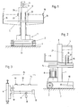
- the device for splitting firewood has a machine frame 1 with a base part 2 and an upright splitting tower 3 with a splitting wedge 4 projecting from this splitting tower.
- a support table 5 is cantilevered on the machine frame 1.
- a bow-like handle 6 on the back of the device is used in connection with the wheels 7 to transport the device over short distances.
- a hydraulic piston-cylinder unit 9, which can be acted on from both sides, is accommodated within the splitting tower 3, a drive motor 8 serving to operate it, a hydraulic control valve 10 and an oil pump 11 and an oil reservoir 12. Between the oil reservoir 12 and the hydraulic control valve 10 there are one Pressure line and a return line provided in the usual way.
- a first switch 14 in the control circuit 15 of the hydraulic control valve 10 is actuated via a switch bracket 13 accommodated in the base part 2, which can be actuated here with the foot.
- the switching bracket for actuating the hydraulic control valve can be operated with the knee.
- photoelectric reflection switches 17 and 18 are fixed at the edge of the support table 5 by means of holders 16, which are slightly offset from one another in the exemplary embodiment shown (FIG. 2) and are directed towards one another.
- These photoelectric reflection switches 17 and 18 are in excitation circuits of relays, which are not shown here, but which in turn have switch contacts 19 and 20, which are arranged in series in the control circuit 15 of the hydraulic control valve 10.
- the height at which the two reflection switches 17 and 18 lie above the support table 5 corresponds to approximately half the working height of the riving knife 4.
- these reflection switches 17 and 18 can also be arranged such that the light beams emitted by them unite with one another Include obtuse angle.
- the operator wears reflectors 22 and 23 on the back of his hand or else he wears work gloves, on the outside of which such reflectors 22 and 23 are fixed.
- Such reflectors are soft and flexible and have an adhesive layer on their back so that they can be fixed to and from a base are repeatedly removable.
- the piece of wood to be split is gripped laterally by the operator with both hands and placed on the support table 5.
- Such a piece of wood is indicated in Fig. 1 by a dashed line 21. If the piece of wood is held in accordance with the regulations, the operator's hands rest against this piece of wood at the side, the reflectors 22 and 23 mentioned taking up the position opposite the displacement area of the riving knife 4 which is illustrated in FIG. 1.
- the light beam emitted by the photoelectric reflection switch 17 and backwashed by the reflector 22 in the correct position triggers a switching pulse by which the switching contact is closed via a relay, not shown here.
- a switching pulse by which the switching contact is closed via a relay, not shown here.
- the photoelectric reflection switch 18 and the reflector 23 assigned to it Now the control valve 10 can be closed via the switching bracket 13 and the switch 14 and the splitting wedge 4 can thereby be lowered. If the operator's hands carrying the reflectors 22 and 23 were not in the position shown in FIG. 1 relative to the piece of wood, the photoelectric reflection switches 17 and / or 18 would not respond and the control valve 10 could not be actuated.
- the control circuit or circuit 15 for the hydraulic control valve 10 is interrupted and the splitting wedge 4 cannot be activated. Since the light beams emitted by the photoelectric reflection switches 17 and 18 are bundled relatively strongly, the security area must be narrowly limited. In Fig. 1, these light rays are indicated by dash-dotted lines.
- the switches 14 and the switching contacts 19 and 20 are arranged in series in the control circuit 15 for the hydraulic control valve 10.
- relay is to be understood in general. This can be a mechanical, electrically controlled switching element or an electronic switching element.
- the protective device is not limited to the device for splitting firewood described here, for example. It can also be used in circular saws, straw mills, choppers or the like, the arrangement of the protective device being adapted to the particular circumstances. In particular in the case of rapidly rotating tools (circular saws), in addition to influencing the control circuit for driving the tool, a braking device which can be activated by the protective device will also be required.
Landscapes
- Engineering & Computer Science (AREA)
- General Engineering & Computer Science (AREA)
- Life Sciences & Earth Sciences (AREA)
- Mechanical Engineering (AREA)
- Wood Science & Technology (AREA)
- Forests & Forestry (AREA)
- Debarking, Splitting, And Disintegration Of Timber (AREA)
- Preliminary Treatment Of Fibers (AREA)
- Operation Control Of Excavators (AREA)
Applications Claiming Priority (2)
| Application Number | Priority Date | Filing Date | Title |
|---|---|---|---|
| AT2350/94 | 1994-12-16 | ||
| AT0235094A AT402708B (de) | 1994-12-16 | 1994-12-16 | Schutzeinrichtung für und an arbeitsmaschinen mit sichbewegenden trenn- und/oder spaltwerkzeugen |
Publications (2)
| Publication Number | Publication Date |
|---|---|
| EP0716907A1 true EP0716907A1 (fr) | 1996-06-19 |
| EP0716907B1 EP0716907B1 (fr) | 1999-03-03 |
Family
ID=3532723
Family Applications (1)
| Application Number | Title | Priority Date | Filing Date |
|---|---|---|---|
| EP95119522A Expired - Lifetime EP0716907B1 (fr) | 1994-12-16 | 1995-12-12 | Dispositif de protection pour machines à outil mobile pour fendre le bois |
Country Status (3)
| Country | Link |
|---|---|
| EP (1) | EP0716907B1 (fr) |
| AT (2) | AT402708B (fr) |
| DE (1) | DE59505194D1 (fr) |
Cited By (1)
| Publication number | Priority date | Publication date | Assignee | Title |
|---|---|---|---|---|
| EP3767152A1 (fr) * | 2019-07-15 | 2021-01-20 | Q-tec Prüfgeräte GmbH | Dispositif de fixation pour une machine et procédé de fonctionnement d'un dispositif de fixation |
Families Citing this family (1)
| Publication number | Priority date | Publication date | Assignee | Title |
|---|---|---|---|---|
| AT527917B1 (de) * | 2024-03-14 | 2025-08-15 | Posch Gmbh | Spaltvorrichtung zum Spalten von Holz |
Citations (4)
| Publication number | Priority date | Publication date | Assignee | Title |
|---|---|---|---|---|
| WO1986006816A1 (fr) * | 1985-05-15 | 1986-11-20 | Northern Food-Line Machines K/S | Systeme de securite associe a des machines de travail |
| EP0438997A2 (fr) * | 1990-01-24 | 1991-07-31 | POSCH LANDMASCHINENBAU Gesellschaft m.b.H. | Dispositif de manipulation pour machine |
| US5168173A (en) * | 1990-05-04 | 1992-12-01 | Control Devices, Inc. | Pushless two-hand run bar apparatus |
| EP0600841A1 (fr) * | 1992-12-04 | 1994-06-08 | STEINEX S.r.l. | Appareil de contrôle pour la prévention d'accident sur presses hydrauliques et similaires, en particulier pour travaux de broyage de pierres |
Family Cites Families (4)
| Publication number | Priority date | Publication date | Assignee | Title |
|---|---|---|---|---|
| DE3002767C2 (de) * | 1978-04-20 | 1983-09-22 | Kube KG Kunkel & Co, 8999 Weiler-Simmerberg | Berührungsschutzvorrichtung für eine Drallkeilspitze bei einer Vorrichtung zum Holzspalten |
| DE3018952A1 (de) * | 1980-05-17 | 1981-11-26 | Fa. Andreas Stihl, 7050 Waiblingen | Motorkettensaege |
| DE3223281A1 (de) * | 1982-06-22 | 1982-12-02 | Wastema W. Steinhauser KG Maschinenfabrik, 7484 Veringenstadt | Einrichtung zum saegen oder schneiden |
| FR2612444B3 (fr) * | 1987-03-17 | 1989-11-03 | Matra | Dispositif de protection a circuit d'antiviolation pour machine a bois |
-
1994
- 1994-12-16 AT AT0235094A patent/AT402708B/de not_active IP Right Cessation
-
1995
- 1995-12-12 AT AT95119522T patent/ATE177042T1/de not_active IP Right Cessation
- 1995-12-12 DE DE59505194T patent/DE59505194D1/de not_active Expired - Fee Related
- 1995-12-12 EP EP95119522A patent/EP0716907B1/fr not_active Expired - Lifetime
Patent Citations (4)
| Publication number | Priority date | Publication date | Assignee | Title |
|---|---|---|---|---|
| WO1986006816A1 (fr) * | 1985-05-15 | 1986-11-20 | Northern Food-Line Machines K/S | Systeme de securite associe a des machines de travail |
| EP0438997A2 (fr) * | 1990-01-24 | 1991-07-31 | POSCH LANDMASCHINENBAU Gesellschaft m.b.H. | Dispositif de manipulation pour machine |
| US5168173A (en) * | 1990-05-04 | 1992-12-01 | Control Devices, Inc. | Pushless two-hand run bar apparatus |
| EP0600841A1 (fr) * | 1992-12-04 | 1994-06-08 | STEINEX S.r.l. | Appareil de contrôle pour la prévention d'accident sur presses hydrauliques et similaires, en particulier pour travaux de broyage de pierres |
Cited By (3)
| Publication number | Priority date | Publication date | Assignee | Title |
|---|---|---|---|---|
| EP3767152A1 (fr) * | 2019-07-15 | 2021-01-20 | Q-tec Prüfgeräte GmbH | Dispositif de fixation pour une machine et procédé de fonctionnement d'un dispositif de fixation |
| US11517951B2 (en) | 2019-07-15 | 2022-12-06 | Q-tec Prüfgeräte GmbH | Safety device for a machine and method of operating a safety device |
| DE102019119137B4 (de) * | 2019-07-15 | 2024-04-18 | Q-tec Prüfgeräte GmbH | Sicherungsvorrichtung für eine Maschine und Verfahren zum Betreiben einer Sicherungsvorrichtung |
Also Published As
| Publication number | Publication date |
|---|---|
| EP0716907B1 (fr) | 1999-03-03 |
| DE59505194D1 (de) | 1999-04-08 |
| ATE177042T1 (de) | 1999-03-15 |
| ATA235094A (de) | 1996-12-15 |
| AT402708B (de) | 1997-08-25 |
Similar Documents
| Publication | Publication Date | Title |
|---|---|---|
| DE2454783A1 (de) | Sicherheitsvorrichtung fuer eine maschine | |
| DE2928949C2 (de) | Verfahren und Vorrichtung zur spanenden Zerlegung von Baumstämmen in allseitig bearbeitete Holzerzeugnisse | |
| DE60023938T2 (de) | Bearbeitunssystem mit schutzvorrichtung für einen tisch für geschützte bearbeitung | |
| EP2363768B1 (fr) | Dispositif de frein de sécurité pour éléments de machines mobiles | |
| DE3212392A1 (de) | Verfahren und vorrichtung zum zerschneiden von stammholz zu stuecken unterschiedlicher laenge | |
| EP1522784B1 (fr) | Dispositif muni d'un système de sécurité | |
| EP0716907B1 (fr) | Dispositif de protection pour machines à outil mobile pour fendre le bois | |
| EP3300869B1 (fr) | Scie à table et poussoir pour cela | |
| DE2404872A1 (de) | Tragbare werkzeugmaschine mit rotierendem schneidwerkzeug | |
| AT401903B (de) | Vorrichtung zum spalten von spaltbaren blöcken | |
| EP3536416A1 (fr) | Procédé de surveillance d'une installation de fabrication ainsi qu'installation de fabrication dotée d'un système de sécurité | |
| EP0584601A1 (fr) | Méthode et dispositif pour le réglage de la position de coupe dans une machine de coupe | |
| CS216682B2 (en) | Shears for the formed steel | |
| DE2903364A1 (de) | Schneidmaschine fuer flachglas | |
| DE3120862A1 (de) | "schere zum abschneiden insbesondere eines furnierpakets" | |
| DE10212215A1 (de) | Sicherheitseinrichtung für Gefahrenräume an Werkzeugmaschinen | |
| DE19516121A1 (de) | Verfahren und Vorrichtung zur fehlersicheren Signalverarbeitung einer Maschinensteuerung | |
| DE3243822A1 (de) | Automatische schutzvorrichtung fuer untertischkappsaegemaschine | |
| DE8517523U1 (de) | Handkreissäge | |
| DE2806262B2 (de) | Einspannvorrichtung für Maschinen zur Bearbeitung von Fensterrahmen | |
| DE102024116645A1 (de) | Sägeeinrichtung | |
| DE19640687A1 (de) | Holzspaltmaschine | |
| DE7506461U (de) | Kappsäge für überstehende Umleimerenden | |
| DE2019498A1 (de) | Kombinierte Blechbearbeitungsmaschine | |
| DE604969C (de) | Saegemaschine zum Schneiden von Zuckerplatten |
Legal Events
| Date | Code | Title | Description |
|---|---|---|---|
| PUAI | Public reference made under article 153(3) epc to a published international application that has entered the european phase |
Free format text: ORIGINAL CODE: 0009012 |
|
| AK | Designated contracting states |
Kind code of ref document: A1 Designated state(s): AT CH DE IT LI |
|
| 17P | Request for examination filed |
Effective date: 19961205 |
|
| GRAG | Despatch of communication of intention to grant |
Free format text: ORIGINAL CODE: EPIDOS AGRA |
|
| 17Q | First examination report despatched |
Effective date: 19980512 |
|
| GRAG | Despatch of communication of intention to grant |
Free format text: ORIGINAL CODE: EPIDOS AGRA |
|
| GRAH | Despatch of communication of intention to grant a patent |
Free format text: ORIGINAL CODE: EPIDOS IGRA |
|
| GRAH | Despatch of communication of intention to grant a patent |
Free format text: ORIGINAL CODE: EPIDOS IGRA |
|
| GRAA | (expected) grant |
Free format text: ORIGINAL CODE: 0009210 |
|
| AK | Designated contracting states |
Kind code of ref document: B1 Designated state(s): AT CH DE IT LI |
|
| PG25 | Lapsed in a contracting state [announced via postgrant information from national office to epo] |
Ref country code: IT Free format text: LAPSE BECAUSE OF FAILURE TO SUBMIT A TRANSLATION OF THE DESCRIPTION OR TO PAY THE FEE WITHIN THE PRESCRIBED TIME-LIMIT;WARNING: LAPSES OF ITALIAN PATENTS WITH EFFECTIVE DATE BEFORE 2007 MAY HAVE OCCURRED AT ANY TIME BEFORE 2007. THE CORRECT EFFECTIVE DATE MAY BE DIFFERENT FROM THE ONE RECORDED. Effective date: 19990303 |
|
| REF | Corresponds to: |
Ref document number: 177042 Country of ref document: AT Date of ref document: 19990315 Kind code of ref document: T |
|
| REG | Reference to a national code |
Ref country code: CH Ref legal event code: EP |
|
| REF | Corresponds to: |
Ref document number: 59505194 Country of ref document: DE Date of ref document: 19990408 |
|
| REG | Reference to a national code |
Ref country code: CH Ref legal event code: NV Representative=s name: DIPL.-ING. ETH H. R. WERFFELI PATENTANWALT |
|
| PLBE | No opposition filed within time limit |
Free format text: ORIGINAL CODE: 0009261 |
|
| STAA | Information on the status of an ep patent application or granted ep patent |
Free format text: STATUS: NO OPPOSITION FILED WITHIN TIME LIMIT |
|
| 26N | No opposition filed | ||
| PGFP | Annual fee paid to national office [announced via postgrant information from national office to epo] |
Ref country code: AT Payment date: 20011214 Year of fee payment: 7 |
|
| PGFP | Annual fee paid to national office [announced via postgrant information from national office to epo] |
Ref country code: CH Payment date: 20011224 Year of fee payment: 7 |
|
| PGFP | Annual fee paid to national office [announced via postgrant information from national office to epo] |
Ref country code: DE Payment date: 20020221 Year of fee payment: 7 |
|
| PG25 | Lapsed in a contracting state [announced via postgrant information from national office to epo] |
Ref country code: AT Free format text: LAPSE BECAUSE OF NON-PAYMENT OF DUE FEES Effective date: 20021212 |
|
| PG25 | Lapsed in a contracting state [announced via postgrant information from national office to epo] |
Ref country code: LI Free format text: LAPSE BECAUSE OF NON-PAYMENT OF DUE FEES Effective date: 20021231 Ref country code: CH Free format text: LAPSE BECAUSE OF NON-PAYMENT OF DUE FEES Effective date: 20021231 |
|
| PG25 | Lapsed in a contracting state [announced via postgrant information from national office to epo] |
Ref country code: DE Free format text: LAPSE BECAUSE OF NON-PAYMENT OF DUE FEES Effective date: 20030701 |
|
| REG | Reference to a national code |
Ref country code: CH Ref legal event code: PL |