EP0716909A1 - Verfahren und Vorrichtung zum Extrudieren von grossen Wabenstrukturen - Google Patents
Verfahren und Vorrichtung zum Extrudieren von grossen Wabenstrukturen Download PDFInfo
- Publication number
- EP0716909A1 EP0716909A1 EP95119161A EP95119161A EP0716909A1 EP 0716909 A1 EP0716909 A1 EP 0716909A1 EP 95119161 A EP95119161 A EP 95119161A EP 95119161 A EP95119161 A EP 95119161A EP 0716909 A1 EP0716909 A1 EP 0716909A1
- Authority
- EP
- European Patent Office
- Prior art keywords
- die
- extrusion
- accordance
- support rod
- thickness
- Prior art date
- Legal status (The legal status is an assumption and is not a legal conclusion. Google has not performed a legal analysis and makes no representation as to the accuracy of the status listed.)
- Granted
Links
- 238000000034 method Methods 0.000 title claims description 23
- 241000264877 Hippospongia communis Species 0.000 title description 43
- 238000001125 extrusion Methods 0.000 claims abstract description 82
- 239000000463 material Substances 0.000 claims abstract description 24
- 238000011144 upstream manufacturing Methods 0.000 claims abstract description 17
- 210000004027 cell Anatomy 0.000 claims description 26
- 210000002421 cell wall Anatomy 0.000 claims description 7
- 229910001220 stainless steel Inorganic materials 0.000 claims description 7
- 239000010935 stainless steel Substances 0.000 claims description 4
- 229910000734 martensite Inorganic materials 0.000 claims description 2
- 239000000919 ceramic Substances 0.000 abstract description 12
- 208000028659 discharge Diseases 0.000 description 17
- 238000013461 design Methods 0.000 description 11
- 229910000831 Steel Inorganic materials 0.000 description 10
- 239000010959 steel Substances 0.000 description 10
- 238000004458 analytical method Methods 0.000 description 8
- 238000004519 manufacturing process Methods 0.000 description 8
- 238000005553 drilling Methods 0.000 description 7
- 230000007423 decrease Effects 0.000 description 6
- 230000000712 assembly Effects 0.000 description 4
- 238000000429 assembly Methods 0.000 description 4
- 238000005452 bending Methods 0.000 description 4
- 150000001875 compounds Chemical class 0.000 description 4
- 238000004873 anchoring Methods 0.000 description 3
- 230000000694 effects Effects 0.000 description 3
- 239000000203 mixture Substances 0.000 description 3
- 230000009467 reduction Effects 0.000 description 3
- 230000008719 thickening Effects 0.000 description 3
- XLYOFNOQVPJJNP-UHFFFAOYSA-N water Substances O XLYOFNOQVPJJNP-UHFFFAOYSA-N 0.000 description 3
- 230000003466 anti-cipated effect Effects 0.000 description 2
- 238000013459 approach Methods 0.000 description 2
- 238000003491 array Methods 0.000 description 2
- 229910052878 cordierite Inorganic materials 0.000 description 2
- JSKIRARMQDRGJZ-UHFFFAOYSA-N dimagnesium dioxido-bis[(1-oxido-3-oxo-2,4,6,8,9-pentaoxa-1,3-disila-5,7-dialuminabicyclo[3.3.1]nonan-7-yl)oxy]silane Chemical compound [Mg++].[Mg++].[O-][Si]([O-])(O[Al]1O[Al]2O[Si](=O)O[Si]([O-])(O1)O2)O[Al]1O[Al]2O[Si](=O)O[Si]([O-])(O1)O2 JSKIRARMQDRGJZ-UHFFFAOYSA-N 0.000 description 2
- 238000009760 electrical discharge machining Methods 0.000 description 2
- 229910000984 420 stainless steel Inorganic materials 0.000 description 1
- 229910000502 Li-aluminosilicate Inorganic materials 0.000 description 1
- PNEYBMLMFCGWSK-UHFFFAOYSA-N aluminium oxide Inorganic materials [O-2].[O-2].[O-2].[Al+3].[Al+3] PNEYBMLMFCGWSK-UHFFFAOYSA-N 0.000 description 1
- 239000011230 binding agent Substances 0.000 description 1
- 230000015572 biosynthetic process Effects 0.000 description 1
- 239000003054 catalyst Substances 0.000 description 1
- 229910010293 ceramic material Inorganic materials 0.000 description 1
- 239000012700 ceramic precursor Substances 0.000 description 1
- 239000004927 clay Substances 0.000 description 1
- 229910052570 clay Inorganic materials 0.000 description 1
- 238000010276 construction Methods 0.000 description 1
- 230000003247 decreasing effect Effects 0.000 description 1
- 239000003599 detergent Substances 0.000 description 1
- 238000010586 diagram Methods 0.000 description 1
- 238000005516 engineering process Methods 0.000 description 1
- 238000011156 evaluation Methods 0.000 description 1
- 239000002657 fibrous material Substances 0.000 description 1
- 238000010304 firing Methods 0.000 description 1
- 239000012530 fluid Substances 0.000 description 1
- 238000010438 heat treatment Methods 0.000 description 1
- 230000002452 interceptive effect Effects 0.000 description 1
- 239000000314 lubricant Substances 0.000 description 1
- 238000003754 machining Methods 0.000 description 1
- 238000005259 measurement Methods 0.000 description 1
- 229910052751 metal Inorganic materials 0.000 description 1
- 239000002184 metal Substances 0.000 description 1
- 230000000704 physical effect Effects 0.000 description 1
- 238000005498 polishing Methods 0.000 description 1
- 239000011214 refractory ceramic Substances 0.000 description 1
- 230000002787 reinforcement Effects 0.000 description 1
- 150000004760 silicates Chemical class 0.000 description 1
- 125000006850 spacer group Chemical group 0.000 description 1
- 239000000758 substrate Substances 0.000 description 1
- 230000000153 supplemental effect Effects 0.000 description 1
- 239000000454 talc Substances 0.000 description 1
- 229910052623 talc Inorganic materials 0.000 description 1
- 238000003466 welding Methods 0.000 description 1
- 238000009763 wire-cut EDM Methods 0.000 description 1
Images

Classifications
-
- B—PERFORMING OPERATIONS; TRANSPORTING
- B28—WORKING CEMENT, CLAY, OR STONE
- B28B—SHAPING CLAY OR OTHER CERAMIC COMPOSITIONS; SHAPING SLAG; SHAPING MIXTURES CONTAINING CEMENTITIOUS MATERIAL, e.g. PLASTER
- B28B3/00—Producing shaped articles from the material by using presses; Presses specially adapted therefor
- B28B3/20—Producing shaped articles from the material by using presses; Presses specially adapted therefor wherein the material is extruded
- B28B3/26—Extrusion dies
- B28B3/269—For multi-channeled structures, e.g. honeycomb structures
Definitions
- the present invention relates to the manufacture of large honeycomb structures and more particularly to a method and apparatus for extruding large honeycomb structures having a high cell count and thin cell walls, for applications such as heat regenerator wheels in turbine engines.
- the lay-up technique can provide ceramic honeycombs with high cell density and thin cell walls.
- the method is both time consuming and expensive, and thus not well suited for the mass production of thin-walled high-cell-density honeycomb structures.
- Ceramic honeycombs have also been made by less expensive extrusion methods, such as disclosed in U.S. Patent No. 3,790,654 to Bagley. In accordance with those methods, plasticized ceramic batch materials are extruded through a honeycomb extrusion die to produce honeycombs for applications such as supports for automotive emissions control catalysts.
- the die assemblies used in these extrusion methods include a steel die or die body in the form of a plate, the plate being provided on the upstream or inlet face with an array of machined feedholes and on the downstream or outlet face with an array of crisscrossing discharge slots.
- the feedholes intersect the discharge slots, supplying batch material thereto which is then shaped during discharge into the crisscrossing or intersecting walls of the desired honeycomb structure.
- the present invention utilizes a relatively thin steel plate to form the die, but provides supplemental support means for die reinforcement.
- the approach taken is to utilize a center rod support or pull rod, passing through the die and anchored to a support behind or upstream of the die, to prevent plate failure and restrict plate distortion under the pressure of extrusion.
- This approach permits the extrusion of a relatively large honeycomb structure with thin walls and a high cell count using a much thinner die than would otherwise be possible.
- lower extrusion pressures than previously thought possible can be used.
- the present invention comprises die apparatus for the extrusion of a honeycomb structure which comprises an extrusion die, typically in the form of a plate, having an inlet face provided with a multiplicity of feedholes for the input of batch material from an upstream direction and an outlet face provided with a multiplicity of discharge slots for the discharge of the batch material as a honeycomb in a downstream direction.
- an extrusion die typically in the form of a plate
- an outlet face provided with a multiplicity of discharge slots for the discharge of the batch material as a honeycomb in a downstream direction.
- Included in the apparatus is at least one support rod, connected to the die and extending in the upstream direction from the die inlet face.
- the upstream-extending end of the support rod is connected to anchoring support means, spaced upstream from the die.
- the support rod and support means act to inhibit movement (reduce stress and strain) on the extrusion die during the extrusion of batch material through the die.
- the invention comprises a method for extruding a honeycomb body of large diameter and high cell count which comprises extruding a batch material from a honeycomb extrusion die of large diameter and high cell count in a downstream direction while applying a supporting force to the die in an upstream direction.
- the supporting force is supplied to central portions of extrusion die by at least one support member or rod connected to the central portion(s) and attached to support means positioned in the upstream direction from the die.
- a honeycomb structure produced by the above method will have a structure which reflects the presence of the support rod during extrusion.
- that structure consists of a central opening in the face of the honeycomb formed by and corresponding to the regions of the die inlet or outlet face blocked by the support rod.
- a central opening is advantageous in that it provides a convenient location for a hub member to facilitate regenerator rotation, as is customary to achieve heat recuperation in a turbine engine environment.
- the support rod is typically connected to the die more or less centrally of the inlet face thereof.
- Simple attachment may be by means of an opening provided in the die through which the support rod extends, with fastening to the die being made by bolting, pinning, or any other means.
- Other attachment options could be used depending on the extrusion pressures anticipated, including options such as welding or cementing the support rod to the inlet face.
- the thickness of the support rod while not critical, is important since thicker rods are more effective in reducing die strain than thinner rods. Ideally the rod will support extrusion stresses with little or no elongation or yield.
- the cross-sectional configuration of the rod may be varied depending on factors such as the method to be used to attach the rod to the die and to the upstream support for the rod.
- the upstream support for the rod may comprise one or more bridging or support members attached to the barrel of the extruder, or attached to a die enclosure or cartridge connected to the extruder.
- Die enclosures or cartridges are conventional structures for mounting dies to the barrels of extruders, and provide a good base for the ultimate support of the die, support rod, and supporting structure for the rod.
- baffle plate or other thick ported plate anchored to the extruder or die enclosure upstream of the die.
- a baffle plate which typically consists simply of a thick metal plate provided with holes through which the batch material is forced during the process of extrusion, can be as thick as desired without interfering with extrusion, and thus can provide a relatively rigid base for a support rod at almost any extrusion pressure to be employed.
- the relative spacing of the support and die can be important if the support is a baffle plate.
- the support rod should be sufficiently long, i.e., the die-support spacing sufficiently large, that any disturbance in batch flow caused by the plate does not disturb the configuration of the extruded honeycomb.
- FIG. 1 and 2 of the drawing A schematic illustration of a preferred die apparatus design for honeycomb extrusion in accordance with the invention is provided in Figs. 1 and 2 of the drawing.
- a die 10 is disposed in a die enclosure or cartridge 12 such that outlet face 10a of the die faces outwardly from the cartridge.
- Die 10 includes discharge slots and feedholes 11, the discharge slots being formed in outlet face 10a and the feedholes connecting with those slots being formed in a die inlet face 10b.
- batch material in the cartridge can be extruded through die 10 and discharged from outlet face 10a as a honeycomb in the conventional fashion.
- Rod 14 is attached to the die by means of a washer 15 and nut 16. The nut is threaded onto one end of rod 14 which extends through a central opening in die 10.
- support rod 14 is attached to baffle plate 18, attachment being by means of cap screws 19 which extend through plate 18 to thread into the base end of support rod 14.
- Baffle plate 18 is edge-supported at the back of cartridge 12 by spacers 20 (and thus ultimately by lip or mask 12a on the die cartridge), but is thicker than die 10 and thus sufficiently stiff and strong to provide substantially immovable support means for anchoring support rod 14 and die 10 during batch extrusion.
- FIGs. 1 and 2 illustrate a preferred die design utilizing only a single support rod, it will be recognized that other designs employing multiple support rods can alternatively be used, where products with multiple openings in the honeycomb structure may be desired.
- a useful die design criterion is to select components and component assemblies capable of operating at extrusion pressures on the order of 1,000-2,000 psi without exceeding the yield stress of any component.
- Materials capable of providing this level of performance have previously been identified, and include as preferred materials the high strength stainless steels. These may comprise ferritic, austenitic, martensitic or precipitation-hardenable types of stainless steels, to be selected based on strength and elastic modulus as required for the component being specified. In general, steel materials having yield strengths of at least 50,000 psi and elastic moduli of at least 28x106 psi will be used.
- finite element analysis An important tool for validating designs intended to operate at these extrusion pressures is finite element analysis, which analyzes a mathematical die model based on the physical properties and dimensions of steel die components to be used. Applying such an analysis to a model of a die such as above described, comprising a die, a baffle plate, a support rod connecting the die and baffle plate, and a rigid surrounding support structure for the assembly, such an analysis can provide accurate predictions of the stresses to be expected at each point in the assembly while in use.
- regions of primary concern in extrusion die assemblies are those regions under the highest tensional stress. Most critical of these are surface regions on the outlet face of the die covering those sections of the die plate experiencing the maximum deflection under extrusion loads.
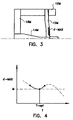
- Fig. 3 of the drawing is a schematic illustration of a stress model of a die assembly incorporating a die with support rod in accordance with the invention as illustrated in Figs. 1 and 2.
- segments 10M, 12M, 14M and 18M model the die 10, cartridge 12, support rod 14 and baffle plate 18, respectively, in Figs. 1 and 2.
- For purposes of stress analysis only one-half of the axially symmetric die assembly of Figs. 1 and 2 needs to be considered, and so that is all that is modeled and shown.
- region ⁇ -max which is located on the outlet face of die element 10M between the supports provided by elements 14M and 12M.
- Other parts of the structure are also under tensional stress, although not so identified or indicated in the drawing, but region ⁇ -max is the region of maximum stress throughout the range of extrusion pressures expected to be encountered in this die.
- Fig. 4 of the drawing illustrates the form of a stress-thickness plot which would be generated by evaluations the stress-thickness function ⁇ -MAX(T) at a given constant extrusion pressure.
- the stress value ⁇ -MAX for a range of die thicknesses is plotted on the y-axis and die thickness T is plotted on the x-axis.
- Plot regions displayed as broken lines represent estimates or projections of die stress based on the foregoing theoretical considerations rather than on actual computed stress data.
- maximum die stress ⁇ -MAX decreases in proportion to die thickness as die thickness T increases from very low values (near the x-y origin of the graph). However, a minimum stress point is reached at an intermediate or optimum thickness point T-opt beyond which further increases in die thickness increase rather than decrease ⁇ -MAX.
- the support rod die of the invention will generally have a plate thickness close to the value, on the plot of increasing die thickness versus decreasing maximum stress level, where maximum die stress reaches the first local minimum for the die configuration and extrusion pressure selected.
- the first local minimum is meant the first stress minimum observed in the maximum stress function of die thickness ⁇ -MAX(T) as die thickness increases to finite values from zero.
- die thicknesses employed in the invention will be within ⁇ 25%, most preferably within ⁇ 10%, of the thickness T-opt at which the first local stress minimum in this function is observed.
- finite element stress analysis of a 30 cm (12 inch)-diameter support rod die model with a 2.22 cm (7/8 inches) support rod at a selected extrusion pressure of 1800 psi revealed a first minimum in the value of the maximum outlet face stress ( ⁇ -max) at a die thickness of about 2.7 cm (1.0625 inches). Maximum stress at this die thickness was only about 16 ksi. Maximum stress increased to about 18.5 ksi as die thickness was reduced to 2.54 cm (1.00 inches) and increased to 19.5 ksi as die thickness was increased to 2.845 cm (1.12) inches.
- the drilling and slotting of support rod extrusion dies to be provided in accordance with the invention can be accomplished using conventional mechanical or electrochemical machining techniques.
- the method of choice for providing feed holes in the inlet face of the die plate is gun drilling. This technique permits the production of a large number of closely spaced holes at hole diameters in the 1 mm (0.040 inches) range, so that a feedhole pattern of the required density for supplying a fine discharge slot array can be provided.
- the discharge slots on the outlet face of the die are formed by the process of electrical discharge machining (EDM).
- EDM electrical discharge machining
- This process is capable of producing discharge slots at slot widths in the 0.005 inch range, such widths being advantageous for the production of the very small wall thicknesses desired for heat regenerator applications.
- EDM also permits the easy formation of long slots, which are needed for the extrusion of large frontal area honeycombs such as herein described.
- any conventional slot pattern can be used for the fabrication of extrusion dies in accordance with the invention, but the preferred slot pattern for this use is of a type referred to in the art as a "compound slot" pattern.
- This pattern described for example in U.S. Patent No. 4,902,216, includes two superimposed arrays of slots.
- the first group of slots referred to as primary slots, is configured in the manner of conventional criss-crossing discharge slots, in that every other slot intersection in the array is supplied with batch material from a single dedicated feedhole.
- the second group of slots comprises slots crossing the slots of the first group, but which are typically slightly wider and shallower than the slots of the first group.
- Slots of the second group are supplied with batch material not by feedholes, but by batch material from slots of the first group.
- the advantage of the compound slot die design is that it permits the extrusion of high cell density substrate honeycombs without the need for providing feed holes at every slot intersection.
- An extrusion die for the extrusion of a circular honeycomb body approximately 30 cm (12 inches) in diameter, 2.70 cm (1.0625 inches) in thickness, and having approximately 988 rectangular cells per square inch of open frontal area is fabricated.
- the die is formed from a steel die blank consisting of a plate of AISI Type 422 stainless steel having a thickness of 2.70 cm (1.0625 inches), this steel when hardened and tempered having a yield strength of about 760 MPa (110 ksi), an ultimate tensile strength of about 960 MPa (140 ksi), and an elongation at failure of about 13%.
- the die blank is first subjected to gun drilling to form an array of feed holes into one face of the blank.
- the feed holes are approximately 1 mm (0.040 inches) in diameter, about 2.494 cm (0.982 inches) in depth, and are drilled at all intersections of a square grid array about 0.163 cm (0.064 inches) on a side projected on the inlet face of the die.
- the drilled die plate is soaked and washed in a detergent solution to completely remove all gun drilling oil from the drilled feed holes.
- the drilled plate is next subjected to a slotting process to form a discharge slot array on the plate surface opposite the feedhole array.
- the location of the feed holes is first carefully gauged to ensure proper feedhole-slot alignment, and then an array of primary and secondary discharge slots is machined into the die plate on the outlet surface thereof.
- the primary discharge slots are approximately 0.152 mm (0.006 inches) in width and 2.743 mm (0.108 inches) in depth, and are spaced 1.143 mm (0.045 inches) apart to form a criss-crossing square cell array with alternate slot intersections positioned over and opening into the previously drilled feedholes.
- the secondary discharge slots are 0.178 mm (0.007 inches) in width, 1.778 mm (0.070 inches) in depth, 1.143 mm (0.045 inches) apart, and are machined in one direction only. That is, one secondary slot is positioned between each two primary slots crossing the die in the vertical direction, but no secondary slots are machined in the horizontal direction, so that a rectangular cell array is formed by the superimposed primary and secondary slots. No feedholes are crossed by the secondary slots.
- a hole about 2.225 cm (0.876 inches) in diameter is next drilled parallel with the feedholes through the center of the face of the machined die. This hole is to accommodate a support rod for the die final die assembly. The die is then cut to round shape and final outer dimensions by wire electrical discharge machining.
- the drilled and slotted die thus provided is next polished by passing a fluid polishing compound repeatedly through the feedhole and slot array.
- the compound used is abrasive medium 956-N-1 available from the Extrudehone Corporation of Erwin, PA.
- a support rod for the die is next provided. It consists of a round tapered rod fabricated of AISI Type 420 stainless steel, hardened and tempered to provide a yield strength of 215 ksi, an ultimate tensile strength of 250 ksi, and an elongation at failure of 8%.
- the rod is 22.225 mm (0.875 inches) in diameter at the end to be fastened to the die and 7.264 cm (2.68 inches) in diameter at the base end to be anchored upstream of the die.
- the base end of the rod is drilled and tapped to accept 28 cap screws, these being provided for later anchoring of the base end to a support member.
- the end of the rod adapted to hold the die is threaded utilizing a round-bottomed thread design for high strength, and a steel nut approximately 2 inches in length and machined with a matching thread is provided as stop means for preventing die flexure in the extrusion direction under the extrusion pressure anticipated.
- the support rod thus provided is fastened by means of the cap screws to a drilled steel baffle plate about 5 cm (2 inches) in thickness and the threaded end of the rod is passed through the die and fitted with a washer and the threaded nut.
- the baffle plate is provided across its entire surface with holes through which batch material to be extruded is fed to the inlet face of the die. Although drilled, this plate has sufficient thickness and stiffness to support the major proportion of the load expected to be exerted on the die and support rod during subsequent extrusion.
- a steel die cartridge is loaded with the assembled die, support rod, and baffle plate, and the cartridge with assembled die components is bolted to the outlet port of a hydraulic ram extruder. A number of extrusion runs are then carried out after loading the extruder with extrudable ceramic batches.
- the batches used for the runs of the example comprise mixtures of clay, talc and alumina together with water and appropriate binders and lubricants. These batches are of the type conventionally used for the extrusion of green ceramic honeycombs, being convertible to cordierite ceramic honeycombs by appropriate heat treatment of the dried honeycombs. Other ceramic batches may alternatively used, composed of other ceramic materials such as lithium aluminosilicates, other silicates, or other refractory ceramics.
- water contents are targeted in the range of 34-35% by weight to achieve viscosities appropriate for extrusion through the die.
- the honeycombs are extruded from the die at extrusion pressures in the 1000-1600 psi range. At these pressures, the flow front from the face of the die is uniform at an extrusion rate of about 1.5 feet/minute, for the batches of lower viscosity and higher water content.
- the extruded honeycombs thus provided are dried and fired on a schedule typical for large ceramic honeycombs of the composition employed. After firing, the cell dimensions of the extruded honeycombs are approximately 0.052 cm by 0.106 cm (0.0205 by 0.04179 inches) in size, yielding a cell count of 1166 cells/in2 of honeycomb frontal area.
- the webs defining the cells are in the range of 0.015-0.017 cm (0.0058-0.0065 inches) in thickness.
- the diameter of the center holes formed by the support rod fastener washer in the extruded fired honeycombs is about 2.05 cm (0.806 inches). Outer diameter part deviations from circularity can be maintained at values not exceeding about 1%.
Landscapes
- Engineering & Computer Science (AREA)
- Manufacturing & Machinery (AREA)
- Chemical & Material Sciences (AREA)
- Ceramic Engineering (AREA)
- Mechanical Engineering (AREA)
- Press-Shaping Or Shaping Using Conveyers (AREA)
- Extrusion Moulding Of Plastics Or The Like (AREA)
- Molding Of Porous Articles (AREA)
Applications Claiming Priority (2)
| Application Number | Priority Date | Filing Date | Title |
|---|---|---|---|
| US08/358,099 US5552102A (en) | 1994-12-16 | 1994-12-16 | Method and apparatus for extruding large honeycombs |
| US358099 | 1994-12-16 |
Publications (2)
| Publication Number | Publication Date |
|---|---|
| EP0716909A1 true EP0716909A1 (de) | 1996-06-19 |
| EP0716909B1 EP0716909B1 (de) | 2001-07-11 |
Family
ID=23408303
Family Applications (1)
| Application Number | Title | Priority Date | Filing Date |
|---|---|---|---|
| EP95119161A Expired - Lifetime EP0716909B1 (de) | 1994-12-16 | 1995-12-06 | Verfahren und Vorrichtung zum Extrudieren von grossen Wabenstrukturen |
Country Status (7)
| Country | Link |
|---|---|
| US (1) | US5552102A (de) |
| EP (1) | EP0716909B1 (de) |
| JP (1) | JPH08276487A (de) |
| KR (1) | KR960022400A (de) |
| BR (1) | BR9505905A (de) |
| DE (1) | DE69521668T2 (de) |
| ES (1) | ES2160658T3 (de) |
Cited By (4)
| Publication number | Priority date | Publication date | Assignee | Title |
|---|---|---|---|---|
| WO2003035345A1 (es) * | 2001-10-26 | 2003-05-01 | Torres Dang, S.L. | Sistema de fabricacion por extrusion |
| ES2190367A1 (es) * | 2001-10-26 | 2003-07-16 | Torres Dang S L | Sistema en un solo paso para la extrusion, corte y preparacion para el secado de ladrillos. |
| ES2199065A1 (es) * | 2002-07-09 | 2004-02-01 | Torres Dang S L | Sistema de construccion de muro de grandes dimensiones en pieza unica. |
| FR3064521A1 (fr) * | 2017-03-29 | 2018-10-05 | Airbus Safran Launchers Sas | Extrudeuse munie d'au moins une broche maintenue en position |
Families Citing this family (15)
| Publication number | Priority date | Publication date | Assignee | Title |
|---|---|---|---|---|
| JP3701802B2 (ja) * | 1998-10-29 | 2005-10-05 | 日本碍子株式会社 | ハニカム製造用口金 |
| US6258392B1 (en) | 1999-10-05 | 2001-07-10 | Celsi Giampietro | Microwaveable pasta pie and pan assembly |
| JP3889194B2 (ja) * | 2000-01-13 | 2007-03-07 | 日本碍子株式会社 | ハニカム構造体 |
| RU2172115C1 (ru) * | 2000-09-28 | 2001-08-20 | Мальцев Андрей Сергеевич | Способ производства экструдированного пищевого продукта из материала, содержащего пищевые волокна, и экструдер |
| CA2481774A1 (en) * | 2002-04-12 | 2003-10-23 | Illinois Valley Holding Company | Apparatus and method for filtering particulate and reducing nox emissions |
| WO2003099416A1 (fr) * | 2002-05-24 | 2003-12-04 | Ngk Insulators, Ltd. | Filtre en nid d'abeille et son procede de fabrication, support pour filtre, dispositif de lavage a contre-courant et collecteur de poussiere |
| RU2240918C1 (ru) * | 2003-04-11 | 2004-11-27 | Государственное образовательное учреждение высшего профессионального образования "Оренбургский государственный университет" | Матрица экструдера для полуфабрикатов малой прочности |
| US7992382B2 (en) * | 2003-08-01 | 2011-08-09 | Illinois Valley Holding Company | Particulate trap system and method |
| JP2007196630A (ja) * | 2006-01-30 | 2007-08-09 | Mitsubishi Materials Corp | Tダイ |
| JP5496205B2 (ja) * | 2008-08-28 | 2014-05-21 | コーニング インコーポレイテッド | 工具ダイ用の耐摩耗性被覆 |
| US9763697B2 (en) | 2008-12-16 | 2017-09-19 | DePuy Synthes Products, Inc. | Anti-infective spinal rod with surface features |
| US8449283B2 (en) * | 2009-06-12 | 2013-05-28 | Corning Incorporated | Dies for forming extrusions with thick and thin walls |
| JP6002209B2 (ja) * | 2012-03-29 | 2016-10-05 | イビデン株式会社 | 押出成形用金型の製造方法 |
| WO2013145215A1 (ja) * | 2012-03-29 | 2013-10-03 | イビデン株式会社 | 押出成形用金型、押出成形用金型の製造方法及びハニカム構造体の製造方法 |
| JP6555340B2 (ja) * | 2016-02-24 | 2019-08-07 | 三菱ケミカル株式会社 | 多穴型押出ダイス、金属化合物押出成形体の製造方法、不飽和アルデヒドおよび/または不飽和カルボン酸製造用触媒押出成形体の製造方法、ならびに不飽和アルデヒドおよび/または不飽和カルボン酸の製造方法 |
Citations (5)
| Publication number | Priority date | Publication date | Assignee | Title |
|---|---|---|---|---|
| FR744632A (de) * | 1933-04-21 | |||
| US3112184A (en) | 1958-09-08 | 1963-11-26 | Corning Glass Works | Method of making ceramic articles |
| US3790654A (en) | 1971-11-09 | 1974-02-05 | Corning Glass Works | Extrusion method for forming thinwalled honeycomb structures |
| US4465652A (en) * | 1983-03-11 | 1984-08-14 | Corning Glass Works | Laminated extrusion die blade support |
| US4902216A (en) | 1987-09-08 | 1990-02-20 | Corning Incorporated | Extrusion die for protrusion and/or high cell density ceramic honeycomb structures |
Family Cites Families (13)
| Publication number | Priority date | Publication date | Assignee | Title |
|---|---|---|---|---|
| US1849431A (en) * | 1929-12-19 | 1932-03-15 | Mayhew Walter Herbert | Extruding die |
| US3559252A (en) * | 1968-02-06 | 1971-02-02 | Schneider & Co | Extrusion apparatus |
| FR2466269A1 (fr) * | 1971-02-24 | 1981-04-10 | Commissariat Energie Atomique | Support de barriere poreuse ceramique |
| US3911070A (en) * | 1973-04-25 | 1975-10-07 | Grace W R & Co | Profile extension process for thermoplastic resins and ceramic thermoplastic resin binder compositions |
| US3986816A (en) * | 1974-09-11 | 1976-10-19 | Phillips Petroleum Company | In-line die fastened to breaker plate for support |
| US4108590A (en) * | 1977-02-07 | 1978-08-22 | Owens-Illinois, Inc. | Extrusion head |
| FR2467067A1 (fr) * | 1979-10-15 | 1981-04-17 | Ceraver | Dispositif pour la fabrication de corps a structure alveolaire par extrusion d'une matiere ceramique, et procede d'obtention dudit dispositif |
| US4409284A (en) * | 1980-07-15 | 1983-10-11 | Kabushiki Kaisha Kobe Seiko Sho | Porous moldings made of accumulated mass of stringy or thready extrudates |
| EP0134277B2 (de) * | 1983-08-26 | 1991-11-13 | Hoechst CeramTec Aktiengesellschaft | Verfahren und Vorrichtung zum Herstellen von polykristallinen, transluzenten Sinterrohren |
| JPH0617004B2 (ja) * | 1987-07-16 | 1994-03-09 | 東陶機器株式会社 | セラミックハニカム構造体の押出し成形方法及び装置 |
| JP2604876B2 (ja) * | 1990-03-27 | 1997-04-30 | 日本碍子株式会社 | セラミックハニカム構造体の製造方法 |
| JPH0486204A (ja) * | 1990-07-31 | 1992-03-18 | Daizo Kajiwara | セラミック管の押出成形方法及び装置 |
| US5403787A (en) * | 1994-02-28 | 1995-04-04 | Corning Incorporated | Extruded ceramic honeycomb and method |
-
1994
- 1994-12-16 US US08/358,099 patent/US5552102A/en not_active Expired - Fee Related
-
1995
- 1995-12-06 ES ES95119161T patent/ES2160658T3/es not_active Expired - Lifetime
- 1995-12-06 DE DE69521668T patent/DE69521668T2/de not_active Expired - Fee Related
- 1995-12-06 EP EP95119161A patent/EP0716909B1/de not_active Expired - Lifetime
- 1995-12-14 BR BR9505905A patent/BR9505905A/pt not_active Application Discontinuation
- 1995-12-16 KR KR1019950051107A patent/KR960022400A/ko not_active Abandoned
- 1995-12-18 JP JP7328958A patent/JPH08276487A/ja not_active Withdrawn
Patent Citations (5)
| Publication number | Priority date | Publication date | Assignee | Title |
|---|---|---|---|---|
| FR744632A (de) * | 1933-04-21 | |||
| US3112184A (en) | 1958-09-08 | 1963-11-26 | Corning Glass Works | Method of making ceramic articles |
| US3790654A (en) | 1971-11-09 | 1974-02-05 | Corning Glass Works | Extrusion method for forming thinwalled honeycomb structures |
| US4465652A (en) * | 1983-03-11 | 1984-08-14 | Corning Glass Works | Laminated extrusion die blade support |
| US4902216A (en) | 1987-09-08 | 1990-02-20 | Corning Incorporated | Extrusion die for protrusion and/or high cell density ceramic honeycomb structures |
Cited By (4)
| Publication number | Priority date | Publication date | Assignee | Title |
|---|---|---|---|---|
| WO2003035345A1 (es) * | 2001-10-26 | 2003-05-01 | Torres Dang, S.L. | Sistema de fabricacion por extrusion |
| ES2190367A1 (es) * | 2001-10-26 | 2003-07-16 | Torres Dang S L | Sistema en un solo paso para la extrusion, corte y preparacion para el secado de ladrillos. |
| ES2199065A1 (es) * | 2002-07-09 | 2004-02-01 | Torres Dang S L | Sistema de construccion de muro de grandes dimensiones en pieza unica. |
| FR3064521A1 (fr) * | 2017-03-29 | 2018-10-05 | Airbus Safran Launchers Sas | Extrudeuse munie d'au moins une broche maintenue en position |
Also Published As
| Publication number | Publication date |
|---|---|
| DE69521668T2 (de) | 2002-05-08 |
| DE69521668D1 (de) | 2001-08-16 |
| ES2160658T3 (es) | 2001-11-16 |
| JPH08276487A (ja) | 1996-10-22 |
| EP0716909B1 (de) | 2001-07-11 |
| US5552102A (en) | 1996-09-03 |
| BR9505905A (pt) | 1998-01-06 |
| KR960022400A (ko) | 1996-07-18 |
Similar Documents
| Publication | Publication Date | Title |
|---|---|---|
| EP0716909B1 (de) | Verfahren und Vorrichtung zum Extrudieren von grossen Wabenstrukturen | |
| CA1053446A (en) | Method and apparatus for forming thin-walled honeycomb structures | |
| US5308568A (en) | Extrusion die and method | |
| EP1663447B1 (de) | Asymmetrischer wabenwandstromfilter mit verbesserter formfestigkeit | |
| US5761787A (en) | Method of making bonded pin extrusion die | |
| US7807250B2 (en) | Wall-flow honeycomb filter with hexagonal channel symmetry | |
| EP0570698A1 (de) | Mehrteiliges Strangpressmundstück | |
| US5070588A (en) | Process for producing ceramic honeycomb structure extrusion dies | |
| US7601194B2 (en) | Asymmetric honeycomb wall-flow filter having improved structural strength | |
| US4118456A (en) | Extrusion die | |
| EP2233264B1 (de) | Strangpressdüse zur Formung von einer Wabenstruktur und Verfahren zu deren Herstellung | |
| US7982158B2 (en) | Method of manufacturing die for forming honeycomb structure and die for forming honeycomb structure | |
| WO2008066797A2 (en) | Extrusion die manufacturing method | |
| US7163389B2 (en) | Extrusion die for honeycomb extrusion molding and manufacturing method therefor | |
| KR101641611B1 (ko) | 세라믹 성형체의 제조 방법, 및 그 성형 장치 | |
| CA2188637A1 (en) | Honeycomb extrusion die and methods | |
| US5906839A (en) | Die for molding honeycomb structure | |
| US5630951A (en) | Methods and apparatus for making honeycomb extrusion dies | |
| EP3414067B1 (de) | Extrusionskomponenten für wabenkörper | |
| EP1287933A2 (de) | Verfahren zur Herstellung einer Extrusionsdüse mit variierenden Stiftabmessungen | |
| EP0143555B1 (de) | Strangpressmatrize für Wabenkörper und Verfahren zur Herstellung derselben | |
| US6287103B1 (en) | Die for manufacturing honeycomb bodies | |
| US6415640B1 (en) | Tool and method for making a tool | |
| US6558151B1 (en) | Low-impedance compound feed extrusion die | |
| DE102015116478A1 (de) | Wärme-/Schallwellen-Umwandlungsbauteil und Wärme-/Schallwellen-Umwandlungseinheit |
Legal Events
| Date | Code | Title | Description |
|---|---|---|---|
| PUAI | Public reference made under article 153(3) epc to a published international application that has entered the european phase |
Free format text: ORIGINAL CODE: 0009012 |
|
| AK | Designated contracting states |
Kind code of ref document: A1 Designated state(s): BE DE ES FR GB IT |
|
| 17P | Request for examination filed |
Effective date: 19961122 |
|
| GRAG | Despatch of communication of intention to grant |
Free format text: ORIGINAL CODE: EPIDOS AGRA |
|
| 17Q | First examination report despatched |
Effective date: 20000919 |
|
| GRAG | Despatch of communication of intention to grant |
Free format text: ORIGINAL CODE: EPIDOS AGRA |
|
| GRAH | Despatch of communication of intention to grant a patent |
Free format text: ORIGINAL CODE: EPIDOS IGRA |
|
| GRAH | Despatch of communication of intention to grant a patent |
Free format text: ORIGINAL CODE: EPIDOS IGRA |
|
| GRAA | (expected) grant |
Free format text: ORIGINAL CODE: 0009210 |
|
| AK | Designated contracting states |
Kind code of ref document: B1 Designated state(s): BE DE ES FR GB IT |
|
| RIN1 | Information on inventor provided before grant (corrected) |
Inventor name: LIPP, (GEORGE) DANIEL Inventor name: LAMBERT DAVID WARD Inventor name: KRAGLE, HARRY ARTHUR |
|
| REF | Corresponds to: |
Ref document number: 69521668 Country of ref document: DE Date of ref document: 20010816 |
|
| ITF | It: translation for a ep patent filed | ||
| REG | Reference to a national code |
Ref country code: ES Ref legal event code: FG2A Ref document number: 2160658 Country of ref document: ES Kind code of ref document: T3 |
|
| ET | Fr: translation filed | ||
| REG | Reference to a national code |
Ref country code: GB Ref legal event code: IF02 |
|
| PLBE | No opposition filed within time limit |
Free format text: ORIGINAL CODE: 0009261 |
|
| STAA | Information on the status of an ep patent application or granted ep patent |
Free format text: STATUS: NO OPPOSITION FILED WITHIN TIME LIMIT |
|
| 26N | No opposition filed | ||
| PGFP | Annual fee paid to national office [announced via postgrant information from national office to epo] |
Ref country code: GB Payment date: 20021104 Year of fee payment: 8 |
|
| PGFP | Annual fee paid to national office [announced via postgrant information from national office to epo] |
Ref country code: FR Payment date: 20021202 Year of fee payment: 8 |
|
| PGFP | Annual fee paid to national office [announced via postgrant information from national office to epo] |
Ref country code: ES Payment date: 20021217 Year of fee payment: 8 |
|
| PGFP | Annual fee paid to national office [announced via postgrant information from national office to epo] |
Ref country code: BE Payment date: 20030116 Year of fee payment: 8 |
|
| PG25 | Lapsed in a contracting state [announced via postgrant information from national office to epo] |
Ref country code: GB Free format text: LAPSE BECAUSE OF NON-PAYMENT OF DUE FEES Effective date: 20031206 |
|
| PG25 | Lapsed in a contracting state [announced via postgrant information from national office to epo] |
Ref country code: ES Free format text: LAPSE BECAUSE OF NON-PAYMENT OF DUE FEES Effective date: 20031209 |
|
| PG25 | Lapsed in a contracting state [announced via postgrant information from national office to epo] |
Ref country code: BE Free format text: LAPSE BECAUSE OF NON-PAYMENT OF DUE FEES Effective date: 20031231 |
|
| BERE | Be: lapsed |
Owner name: *CORNING INC. Effective date: 20031231 |
|
| GBPC | Gb: european patent ceased through non-payment of renewal fee |
Effective date: 20031206 |
|
| PG25 | Lapsed in a contracting state [announced via postgrant information from national office to epo] |
Ref country code: FR Free format text: LAPSE BECAUSE OF NON-PAYMENT OF DUE FEES Effective date: 20040831 |
|
| REG | Reference to a national code |
Ref country code: FR Ref legal event code: ST |
|
| REG | Reference to a national code |
Ref country code: ES Ref legal event code: FD2A Effective date: 20031209 |
|
| PG25 | Lapsed in a contracting state [announced via postgrant information from national office to epo] |
Ref country code: IT Free format text: LAPSE BECAUSE OF NON-PAYMENT OF DUE FEES;WARNING: LAPSES OF ITALIAN PATENTS WITH EFFECTIVE DATE BEFORE 2007 MAY HAVE OCCURRED AT ANY TIME BEFORE 2007. THE CORRECT EFFECTIVE DATE MAY BE DIFFERENT FROM THE ONE RECORDED. Effective date: 20051206 |
|
| PGFP | Annual fee paid to national office [announced via postgrant information from national office to epo] |
Ref country code: DE Payment date: 20070131 Year of fee payment: 12 |
|
| PG25 | Lapsed in a contracting state [announced via postgrant information from national office to epo] |
Ref country code: DE Free format text: LAPSE BECAUSE OF NON-PAYMENT OF DUE FEES Effective date: 20080701 |