EP0716942B1 - Aufhängungssystem zur Steuerung der seitlichen Verlagerung eines Rades - Google Patents
Aufhängungssystem zur Steuerung der seitlichen Verlagerung eines Rades Download PDFInfo
- Publication number
- EP0716942B1 EP0716942B1 EP95119567A EP95119567A EP0716942B1 EP 0716942 B1 EP0716942 B1 EP 0716942B1 EP 95119567 A EP95119567 A EP 95119567A EP 95119567 A EP95119567 A EP 95119567A EP 0716942 B1 EP0716942 B1 EP 0716942B1
- Authority
- EP
- European Patent Office
- Prior art keywords
- lever
- wishbone
- wheel
- suspension system
- wheel support
- Prior art date
- Legal status (The legal status is an assumption and is not a legal conclusion. Google has not performed a legal analysis and makes no representation as to the accuracy of the status listed.)
- Expired - Lifetime
Links
- 239000000725 suspension Substances 0.000 title claims description 58
- 238000006073 displacement reaction Methods 0.000 title claims description 16
- 230000033001 locomotion Effects 0.000 claims description 20
- 125000006850 spacer group Chemical group 0.000 claims description 3
- 230000000694 effects Effects 0.000 description 2
- 238000005299 abrasion Methods 0.000 description 1
- 239000000969 carrier Substances 0.000 description 1
- 238000009795 derivation Methods 0.000 description 1
- 238000012986 modification Methods 0.000 description 1
- 230000004048 modification Effects 0.000 description 1
- 230000000737 periodic effect Effects 0.000 description 1
Images




Classifications
-
- B—PERFORMING OPERATIONS; TRANSPORTING
- B62—LAND VEHICLES FOR TRAVELLING OTHERWISE THAN ON RAILS
- B62D—MOTOR VEHICLES; TRAILERS
- B62D17/00—Means on vehicles for adjusting camber, castor, or toe-in
-
- B—PERFORMING OPERATIONS; TRANSPORTING
- B60—VEHICLES IN GENERAL
- B60G—VEHICLE SUSPENSION ARRANGEMENTS
- B60G3/00—Resilient suspensions for a single wheel
- B60G3/18—Resilient suspensions for a single wheel with two or more pivoted arms, e.g. parallelogram
- B60G3/20—Resilient suspensions for a single wheel with two or more pivoted arms, e.g. parallelogram all arms being rigid
- B60G3/26—Means for maintaining substantially-constant wheel camber during suspension movement ; Means for controlling the variation of the wheel position during suspension movement
-
- B—PERFORMING OPERATIONS; TRANSPORTING
- B60—VEHICLES IN GENERAL
- B60G—VEHICLE SUSPENSION ARRANGEMENTS
- B60G2204/00—Indexing codes related to suspensions per se or to auxiliary parts
- B60G2204/10—Mounting of suspension elements
- B60G2204/14—Mounting of suspension arms
- B60G2204/143—Mounting of suspension arms on the vehicle body or chassis
-
- B—PERFORMING OPERATIONS; TRANSPORTING
- B60—VEHICLES IN GENERAL
- B60G—VEHICLE SUSPENSION ARRANGEMENTS
- B60G2204/00—Indexing codes related to suspensions per se or to auxiliary parts
- B60G2204/40—Auxiliary suspension parts; Adjustment of suspensions
- B60G2204/42—Joints with cam surfaces
Definitions
- the present invention relates to a wheel suspension system according to the precharacterizing part of claim 1.
- Suspension systems support and cushion the ride of a vehicle.
- One type of conventional wheel suspension system involves a wishbone design, as generally shown in FIGs. 1, 2A, and 2B.
- the traditional wishbone suspension system includes an upper wishbone and lower wishbone connected to a wheel support on one end and a vehicle chassis on the other end.
- the upper and lower wishbones are spaced above and below the center line of the wheel support as defined by the axle of the wheel.
- Related art includes systems that have been designed to provide more uniform contact of the tire to the road during movements of the wheel and systems designed to reduce roll center movement and camber changes.
- U.S. Patent No. 5,114,176 discloses a suspension system for a steered wheel in which the contact between the wheel and ground is maintained substantially uniform during all movements of the wheel.
- the suspension system includes an axle carrier having a bifurcated upper portion consisting of inwardly extending arms that are pivotally connected through a pin-type joint to a pair of inwardly facing arm sections of a Y-shaped upper arm. Additionally, a generally Y-shaped lower arm is pivotally supported along a pair of brackets affixed to the body.
- U.S. Patent No. 5,286,052 discloses a double wishbone suspension system for a motor vehicle.
- the suspension system includes a lower transversely extending control arm and an upper control arm, which are pivotally connected to lower and upper wheel carriers, respectively.
- This patent is directed to achieving reduced roll center movement and enables wheel camber changes relative to the vehicle body during vertical movement of the suspension travel, as the wheel responds to changing road conditions. While various suspension systems have attempted to overcome various problems with standard suspension systems, none have allowed the successful control of horizontal displacement of the wheel relative to the center line of the chassis of the vehicle.
- WO-A-94/12359 discloses a wheel suspension system comprising a wheel support and an arm assembly including an arm having a first end pivotally connected to the wheel support and a second end pivotally connected to a vehicle chassis, and a lever pivotally connected to the wheel support and engaged with the second end of the arm, wherein the arm assembly controls the camber angle of the wheel in response to movement of the wheel.
- An advantage of the present invention is its simple design that is nevertheless capable of providing control over the lateral displacement of the wheel in response to vertical movement of the wheel. Another advantage is that the suspension system can be used with wishbones presently available for use on vehicles' chassis by integrating an appropriately designed lever and bracket into the wheel suspension system. Additional features and advantages of the invention will be set forth in the description which follows, and in part will be apparent from the description, or may be learned by practice of the invention. The objects and other advantages of the invention will be realized and attained by the wheel suspension system particularly pointed out in the written description and claims hereof as well as the appended drawings.
- the conventional wishbone suspension system illustrated in FIGs. 1, 2A and 2B is designated generally by the reference numeral 20.
- the conventional wishbone suspension system 20 includes a wheel support 22, an upper wishbone 24 and lower wishbone 26.
- the upper and lower wishbones 24, 26 are connected at one end to the wheel support 22 and at their opposite ends to a vehicle chassis 28.
- the wheel support 22 rotatably supports a wheel 30 on which a tire 32 is mounted.
- the tire 32 and accompanying wheel support 22 are moved vertically.
- the wheel 30 moves inward, i.e. toward the chassis 28.
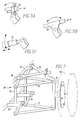
- FIGs. 3A-3D schematically illustrate the progression from a support bar directly connected to a chassis, to a support bar indirectly connected to a chassis, to two different lever arrangements that exploit the advantages of an indirect connection.
- FIG. 3A is a schematic showing the movement of a single support bar 34 that is pivotally connected to the vehicle chassis 28. As the support bar 34 is raised and lowered, the support bar 34 forms an arc, as the unattached end of the support bar 34 moves closer to the chassis 28.
- FIG. 3B shows a support bar 34 attached to an intermediate bar 36, which is attached to the vehicle chassis 28. While pivoting the support bar 34 may move the unattached end of support bar 34 closer to the chassis 28, the simultaneous movement of the intermediate bar 36 in a counterclockwise direction can be used to offset the reduced distance between the free end of the support bar 34 and the center line of the vehicle chassis 28 caused by rotation of support bar 34. Similarly, a lever slidably attached to a wheel support could offset lateral displacement in the wheel as the wheel is vertically deflected.
- FIG. 3C shows an embodiment utilizing a one piece lever 38 that includes the intermediate bar 36.
- the lever 38 is attached to the chassis 28 to move the suspension bar 34 that is attached to the end of the lever 34. As the lever is moved counterclockwise, and the lever 38 and support bar 34 rotate upward, the support bar 34 will be moved to the right a predetermined distance.
- FIG. 3D schematically shows another lever 38 utilizing a two segment design.
- the two segments are pivotally connected to the chassis 28 as well as to one another.
- various multi-segment lever designs can provide the amount of compensation for lateral movement in the wheel support according to the demands of the application.
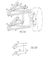
- FIGs. 4A and 4B An exemplary embodiment of a wheel suspension system in accordance with the present invention is shown in FIGs. 4A and 4B and is designated generally by the reference numeral 40.
- the wheel suspension system corresponds to a wheel on the right side of a vehicle.
- the invention may be utilized for one or both sets of wheels in the front or rear of the vehicle or the right side or left side of a vehicle only. This may vary according to the type of vehicle implementing the present invention. For example, in race car designs where the vehicle typically is driven in a single direction around a track, the inside or outside tires may be particularly prone to tire wear and abrasion due to the lateral displacement of the tires during the race.
- the invention can also be utilized in conjunction with both the steered wheels and non-streered wheels of a vehicle.
- the wishbone assembly also includes a lever 56, which is connected to a bracket 58 mounted on the chassis 46.
- the lever 56 extends between the wheel support 42 and each of the second ends 54 of the wishbone 50.
- the lever 56 slidably engages the wheel support 42 and pivotally connects to the second ends 54 of the wishbone 50.
- the bracket 58 pivotally supports the lever 56 between the wheel support 42 and each of the second ends 54 of the wishbone 50. Accordingly, the wishbone assembly 48 controls the lateral displacement of the wheel 44 in response to movement of the wheel 44.
- the lever is designed to control the extent to which the wheel 44 is displaced.
- the lever 56 may include a bent portion 60 between the wheel support 42 and each of the second ends 54 of the wishbone 50.
- the extent to which the bent portion 60 pivots relative to the vertical movement of the wheel support 42 is a factor in controlling the degree of lateral displacement offset by the wishbone assembly 48.
- the lever 56 includes an end 62 extending towards the second ends 54 of the wishbone 50.
- the end 62 of the lever 56 extends away from the wheel support 42 when an axle 64 of the wheel support 42 is substantially perpendicular to a longitudinal center line running the length of the vehicle chassis 46 at axle height. As shown in FIG.
- the first end 52 of the wishbone 50 pivotally connects with the wheel support 42 at a location spaced transversely a greater distance from a longitudinal center line of the vehicle chassis 46 than a corresponding location along the wheel support 42 for slidably engaging the lever 56.
- This embodiment prevents lever 56, which extends through a slidable collar, from slipping off of the collar or from reaching and rubbing the tire as the wheel support 42 moves up and down.
- FIGs. 5A, 5B, and 5C illustrate several alternatives for receiving the lever 56 in the wishbone assembly of the present invention.
- FIG. 5A shows a double hinge 66 pivotally connected to the wheel support 42.
- the double hinge 60 preferably includes rollers to facilitate reciprocating movement of the lever 56.
- FIG. 5B shows another preferred wishbone assembly 48 that includes a sliding collar 68 for receiving the lever 56.
- the sliding collar 68 also is pivotally connected to the wheel support 42.
- a telescoping member 70 is provided on the wheel support for receiving the lever 56.
- the telescoping member 70 is pivotally connected to the wheel support 42.
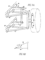
- FIGs. 6A and 6B illustrate a double wishbone and double lever embodiment.
- a preferred wishbone assembly 48 includes a secondary wishbone 72 having a first end 74 pivotally connected to the wheel support 42 and second ends 76 opposite the first end 74.
- the wishbone assembly 48 includes a secondary lever 78, which extends between the wheel support 42 and each of the second ends 76 of the secondary wishbone 72.
- the secondary lever 78 slidably engages the wheel support 42 and pivotally connects to the second ends 76 of the secondary wishbone 72.
- the wishbone assembly 48 includes a secondary bracket 80 mounted on the chassis 46 for pivotally supporting the secondary lever 78 between the wheel support 42 and each of the second ends 76 of the secondary wishbone 72.
- the wishbone assembly 48 includes a secondary wishbone 72 pivotally connected to the wheel support 42 and operatively connected to the wishbone 50.
- the spacer bar 82 pivotally connects the second ends 76 of the secondary wishbone 72 and the second ends 54 of the wishbone 50.
- the wishbone assembly 48 includes a support bar 84 pivotally connected to the second ends 76 of the secondary wishbone 72.
- the wishbone assembly 48 includes a secondary bracket 80 mounted on the chassis 46 for pivotally supporting the support bar 84.
- the wishbone assembly 48 includes a secondary wishbone 72 having a first end 74 pivotally connected to the wheel support 42 and end portions 76 opposite the first end 74.
- the wishbone assembly 48 includes a secondary lever 78 extends between the lever 56 and each of the end portions 76.
- the secondary lever 78 pivotally connects to the lever 56 and the end portions 76 of the secondary wishbone 72.
- the wishbone assembly 48 includes a secondary bracket 80 mounted on the chassis 46 for pivotally supporting the secondary lever 78 between the lever 56 and the end portions 76 of the secondary wishbone 72.
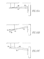
- FIGs. 10A, 10B, 10C, 11 and 12 show yet another embodiment of the present invention.
- FIGs. 10A, 10B, and 10C schematically illustrate a multiple segment lever having each of its segments supported and illustrate a wheel in an at rest condition, in a raised position, and in a lowered condition, respectively.
- the arrow represents that a portion of the lever preferably has an adjustable length feature, such as that encompassed by a telescoping member.
- FIGs. 11 and 12 illustrate two similar perspective views illustrating a preferred embodiment of a multiple segment lever arrangement.
- the wishbone assembly 48 includes a second bracket 86 depending from the chassis 46 and disposed above the wishbone assembly 48 for pivotally supporting the lever 56 between the wheel support 42 and each of the second ends 54 of the wishbone 50.
- the portion of the lever 56 between the bracket 58 and second bracket 86 is pivotally connected and adapted to have an adjustable length.
- the lever 56 includes a first lever segment 88 having a first end 90 slidably engaging the wheel support 42 and a second end 92 opposite the first end 90.
- the lever 56 includes a second lever segment 94 having a first end 96 pivotally connected to the second ends 54 of the wishbone 50 and a second end 98 opposite the first end 96.
- the second ends 92, 98 of the first and second lever segments 88, 94 are pivotally connected to each other.
- the wishbone assembly 48 includes bracket 58 is mounted on the chassis 46 for pivotally supporting the first lever segment 88 between the wheel support 42 and the second end 92 of the first lever segment 88.
- the wishbone assembly 48 includes a second bracket 86 is mounted on the chassis 46 for pivotally supporting the second lever segment 94 between the second ends 54 of the wishbone 50 and the second end 98 of the second lever segment 94.
- the wishbone assembly 48 controls lateral displacement of the wheel in response to vertical movement of the wheel 44.
- the wishbone assembly 48 may further include a secondary wishbone 72 having a first end 74 pivotally connected to the wheel support 42 and second ends 76 opposite the first ends 74 operatively connected to the wishbone 50.
- the wishbone assembly 48 includes a spacer bar 82 pivotally connected to the second ends 76 of the secondary wishbone 72 and the second ends 54 of the wishbone 50.
- the wishbone assembly 48 includes a support bar 84 pivotally connected to the second ends 76 of the secondary wishbone 72.
- a secondary bracket 80 mounted on the chassis 46 pivotally supports the support bar 84.
- the first and second lever segments 88, 94 have an adjustable length and more preferably include a telescoping member.
- the wishbone assembly of the present invention maintains the wheel 44 and wheel support 42 a predetermined lateral distance from a longitudinal center line running the length of the vehicle chassis 46 in response to movement of the wheel in a plane perpendicular to the predetermined distance.
- the actual amount of lateral displacement of the wheel in response to various degrees of vertical displacement both in a raised and lowered direction are dictated by the design requirements of a particular vehicle. For example, the requirements for a race car, go-cart, luxury vehicle, and semitrailer truck may vary dramatically according to the desires of the manufacturer and the advantages to be gained in cost, safety, and performance throughout the life of the particular vehicle.
- lever is intended to define a mechanical linkage that utilizes the principles disclosed in the present invention; namely, a linkage that slidably engages the wheel support 42 and either directly or through some number of intermediate linkage segments connects to a wishbone 50.
- Some or all of the various segments of the linkage mechanism are pivotally connected to the chassis 46 of the vehicle as required by the particular design to cause the desired control over the horizontal displacement of the wheel support 42.
- the range of motion for swinging the lever has a compensation effect in a single direction starting from the position of the wishbone where it points directly away from the vehicle chassis.
- the direction is upward.
- the wishbone will reduce the lateral displacement of the wheel caused by the swing of the lever.
- the angle of the wishbone tends to reduce the absolute distance between the wheel support and the vehicle chassis.
- the single piece lever embodiment now magnifies the lateral displacement effect instead of compensating for it. For certain designs, this situation may be efficient and acceptable.
- the compensation occurs both when the wishbone angles itself in a positive and negative swing relative to a direction away from the vehicle chassis.
- the wishbone may be a single triangular element as opposed to a V-shaped element having two arms. Additionally, it should be understood that a single bar or arm can be substituted for and is meant to be included with the wishbone element.
- the term wishbone is meant to include reasonable derivations therefrom including a bar or pipe that can be pivotally connected on its ends.
Landscapes
- Engineering & Computer Science (AREA)
- Mechanical Engineering (AREA)
- Chemical & Material Sciences (AREA)
- Combustion & Propulsion (AREA)
- Transportation (AREA)
- Vehicle Body Suspensions (AREA)
Claims (19)
- Radaufhängungssystem (40) mit:dadurch gekennzeichnet, daßeinem Radträger (42) um drehbaren Tragen eines Rades (44), das seitlich in einem vorbestimmten Abstand von einem Fahrzeugrahmen (46) angeordnet ist;einer Armanordnung (48) zum schwenkbaren Verbinden des Radträgers (42) mit dem Fahrzeugrahmen (46), wobei die Armanordnung (48) aufweist:einen Arm (50), der ein erstes Ende (52), das schwenkbar mit dem Radträger (42) verbunden ist, und ein zweites Ende (54) aufweist, das dem ersten Ende (52) gegenüberliegt;einen Hebel (56), der sich zwischen dem Radträger (42) und dem zweiten Ende (54) des Armes (50) erstreckt; undeinen Halter (58), der an dem Rahmen (46) zum schwenkbaren Abstützen des Hebels (56) zwischen dem Radträger (42) und dem zweiten Ende (54) des Armes (50) montiert ist;
der Hebel (56) mit dem Radträger (42) gleitend in Eingriff steht und mit dem zweiten Ende (54) des Armes (50) schwenkbar verbunden ist, wodurch die Armanordnung (48) die seitliche Verlagerung des Rades in Abhängigkeit von der vertikalen Bewegung des Rades steuert. - Radaufhängungssystem (40) nach Anspruch 1, wobei der Arm (50) ein Querlenkerarm ist, der ein erstes Ende (52) und zweite Enden (54) aufweist, die dem ersten Ende (52) gegenüberliegen.
- Radaufhängungssystem (40) nach Anspruch 2, wobei der Hebel (56) einen gebogenen Abschnitt (60) zwischen dem Radträger (42) und jedem der zweiten Enden (54) des Querlenkerarmes (50) aufweist.
- Radaufhängungssystem (40) nach Anspruch 2 oder 3, wobei der Hebel (56) ein Ende (62) aufweist, das sich zu den zweiten Enden (54) des Querlenkerarmes (50) hin erstreckt, wobei sich das Ende (62) des Hebels (56) von dem Radträger (42) weg erstreckt, wenn eine Achse (64) des Radträgers (42) im wesentlichen senkrecht zu einer zur Länge des Fahrzeugrahmens (46) in Achshöhe verlaufenden Längsmittellinie ist.
- Radaufhängungssystem (40) nach einem der Ansprüche 2 bis 4, wobei das erste Ende (52) des Querlenkerarmes (50) den Radträger (42) an einer Stelle schwenkbar verbindet, die seitlich in einem größeren Abstand von einer Längsmittellinie des Fahrzeugrahmens (46) als eine entsprechende Stelle entlang des Radtrdgers (42) zum gleitenden Eingreifen des Hebels (56) angeordnet ist.
- Radaufhängungssystem (40) nach einem der Ansprüche 2 bis 5, wobei die Querlenkerarmanordnung (48) ein Doppelgelenk (66) zum Aufnehmen des Hebels (56) aufweist, wobei das Doppelgelenk (66) mit dem Radträger (42) schwenkbar verbunden ist.
- Radaufhängungssystem (40) nach einem der Ansprüche 2 bis 5, wobei die Querlenkerarmanordnung (48) eine Gleitmuffe (68) zum Aufnehmen des Hebels (56) aufweist, wobei die Gleitmuffe (68) mit dem Radträger (42) schwenkbar verbunden ist.
- Radaufhängungssystem (40) nach einem der Ansprüche 2 bis 5, wobei die Querlenkerarmanordnung (48) ein Teleskopteil (70) zum Aufnehmen des Hebels (56) aufweist, wobei das Teleskopteil (70) mit dem Radträger (42) schwenkbar verbunden ist.
- Radaufhängungssystem (40) nach einem der Ansprüche 2 bis 8, wobei die Querlenkerarmanordnung (48) aufweist:einen zweiten Querlenkerarm (72), der ein erstes Ende (76), das mit dem Radträger (42) schwenkbar verbunden ist, und zweite Enden (76) aufweist, die dem ersten Ende (74) gegenüberliegen; undeinen zweiten Halter (80), der an dem Rahmen (46) zum schwenkbaren Abstützen jedes der zweiten Enden (76) des zweiten Querlenkerarmes (72) montiert ist.
- Radaufhängungssystem (40) nach Anspruch 9, wobei die Querlenkerarmanordnung (48) einen zweiten Hebel aufweist, der mit den zweiten Enden (76) des zweiten Querlenkerarmes (72) schwenkbar verbunden ist und von dem zweiten Halter (80) schwenkbar abgestützt ist.
- Radaufhängungssystem (40) nach Anspruch 10, wobei sich der zweite Hebel (78) zwischen dem Radträger (42) und jedem der zweiten Enden (76) des zweiten Querlenkerarmes (72) erstreckt, wobei der zweite Hebel (78) mit dem Radträger (42) gleitend in Eingriff steht, wobei der zweite Halter (80) den zweiten Hebel (78) zwischen dem Radträger (42) und jedem der zweiten Enden (76) des zweiten Querlenkerarmes (72) schwenkbar abstützt.
- Radaufhängungssystem (40) nach Anspruch 10, wobei sich der zweite Hebel (78) zwischen dem Hebel (56) und jedem der zweiten Enden (76) des zweiten Querlenkerarmes (72) erstreckt, wobei der zweite Hebel (78) mit dem Hebel (56) schwenkbar verbunden ist, wobei der zweite Halter (80) den zweiten Hebel (78) zwischen dem Hebel (56) und den zweiten Enden (76) des zweiten Querlenkerarmes (72) schwenkbar abstützt.
- Radaufhängungssystem (40) nach Anspruch 9, wobei die Querlenkerarmanordnung (48) einen Zwischenstab (82) aufweist, der mit den zweiten Enden (76) des zweiten Querlenkerarmes (72) und den zweiten Enden (54) des Querlenkerarmes (50) schwenkbar verbunden ist.
- Radaufhängungssystem (40) nach Anspruch 13, wobei die Querlenkerarmanordnung (48) einen Stützstab (84) aufweist, der mit den zweiten Enden (76) des zweiten Querlenkerarmes (72) schwenkbar verbunden ist und von dem zweiten Halter (80) schwenkbar abgestützt ist.
- Radaufhängungssystem (40) nach einem der Ansprüche 2 bis 14, wobei die Querlenkerarmanordnung (48) einen zweiten Halter (86) aufweist, der von dem Rahmen (46) abhängig ist und oberhalb der Querlenkerarmanordnung (48) zum schwenkbaren Abstützen des Hebels (56) zwischen dem Radträger (42) und jedem der zweiten Enden (54) des Querlenkerarmes (50) angeordnet ist, wobei der Abschnitt des Hebels (56) zwischen dem Halter (58) und dem zweiten Halter (86) derart schwenkbar verbunden und angepaßt ist, daß dieser in der Länge einstellbar ist.
- Radaufhängungssystem (40) nach Anspruch 15, wobeider Hebel (56) ein erstes Hebelsegment (88) aufweist, das ein erstes Ende (90), das mit dem Radträger (42) gleitend in Eingriff steht, und ein zweites Ende (92) aufweist, das dem ersten Ende (90) gegenüberliegt, wobei der Hebel (56) ein zweites Hebelsegment (94) aufweist, das ein erstes Ende (96), das mit den zweiten Enden (54) des Querlenkerarmes (50) schwenkbar verbunden ist, und ein zweites Ende (98) aufweist, das dem ersten Ende (96) gegenüberliegt, wobei die zweiten Enden (92, 98) des ersten und des zweiten Hebelsegments (88, 94) schwenkbar miteinander verbunden sind;wobei der Halter (58) das erste Hebelsegment (88) zwischen dem Radträger (42) und dem zweiten Ende (92) des ersten Hebelsegments (88) schwenkbar abstützt; undwobei der zweite Halter (86) das zweite Hebelsegment (94) zwischen den zweiten Enden (54) des Querlenkerarmes (50) und dem zweiten Ende (98) des zweiten Hebelsegments (94) schwenkbar abstützt.
- Radaufhängungssystem (40) nach Anspruch 16, wobei zumindest das eine der zweiten Enden (92, 98) des ersten und des zweiten Hebelsegments (88, 94) in der Länge einstellbar ist.
- Radaufhängungssystem (40) nach Anspruch 17, wobei die Segmente (88, 94) mit einer einstellbaren Länge ein Teleskopteil aufweisen.
- Radaufhängungssystem (40) nach einem der Ansprüche 2 bis 18, wobei die Querlenkerarmanordnung (48) das Rad (44) in einem im wesentlichen konstanten, vorbestimmten seitlichen Abstand von einer zur Länge des Fahrzeugrahmens (46) verlaufenden Längsmittellinie in Abhängigkeit von der Bewegung des Rades (44) in einer zu dem vorbestimmten Abstand senkrechten Ebene hält.
Applications Claiming Priority (2)
| Application Number | Priority Date | Filing Date | Title |
|---|---|---|---|
| US08/356,579 US5498019A (en) | 1994-12-15 | 1994-12-15 | Suspension system for controlling lateral displacement of a wheel |
| US356579 | 1994-12-15 |
Publications (2)
| Publication Number | Publication Date |
|---|---|
| EP0716942A1 EP0716942A1 (de) | 1996-06-19 |
| EP0716942B1 true EP0716942B1 (de) | 2000-03-29 |
Family
ID=23402043
Family Applications (1)
| Application Number | Title | Priority Date | Filing Date |
|---|---|---|---|
| EP95119567A Expired - Lifetime EP0716942B1 (de) | 1994-12-15 | 1995-12-12 | Aufhängungssystem zur Steuerung der seitlichen Verlagerung eines Rades |
Country Status (3)
| Country | Link |
|---|---|
| US (1) | US5498019A (de) |
| EP (1) | EP0716942B1 (de) |
| DE (1) | DE69515970T2 (de) |
Cited By (1)
| Publication number | Priority date | Publication date | Assignee | Title |
|---|---|---|---|---|
| DE102018205788A1 (de) | 2018-04-17 | 2019-10-17 | Audi Ag | Radaufhängung für einen Kraftwagen, Halteanordnung sowie Kraftwagen |
Families Citing this family (26)
| Publication number | Priority date | Publication date | Assignee | Title |
|---|---|---|---|---|
| US5937967A (en) * | 1997-09-03 | 1999-08-17 | Morgan; Frank O. | Mobile scaffolding apparatus with retractable wheels |
| US6173978B1 (en) * | 1999-05-07 | 2001-01-16 | Zero Roll Suspension Corporation | Zero roll suspension system |
| US6550797B2 (en) * | 2000-11-22 | 2003-04-22 | Zero Roll Suspension, Llc | Zero roll suspension system |
| US20040046350A1 (en) * | 2001-05-21 | 2004-03-11 | Wagner Engineering, Llc | Method and apparatus for suspending a vehicular wheel assembly |
| FR2839280B1 (fr) * | 2002-05-06 | 2004-10-22 | Joel Guitteaud | Suspension amelioree pour vehicule terrestre |
| US20040178600A1 (en) * | 2003-03-10 | 2004-09-16 | Wagner Engineering, Llc | Method and apparatus for suspending a vehicle |
| US7510199B2 (en) * | 2003-04-02 | 2009-03-31 | Yamaha Hatsudoki Kabushiki Kaisha | Off-road vehicle with wheel suspension |
| US7287619B2 (en) | 2003-04-02 | 2007-10-30 | Yamaha Hatsudoki Kabushiki Kaisha | Air intake system for off-road vehicle |
| US7438147B2 (en) | 2003-04-02 | 2008-10-21 | Yamaha Hatsudoki Kabushiki Kaisha | Transmission for off-road vehicle |
| US7367417B2 (en) * | 2003-04-02 | 2008-05-06 | Yamaha Hatsudoki Kabushiki Kaisha | Floor arrangement for off-road vehicle |
| US7357211B2 (en) * | 2003-04-02 | 2008-04-15 | Yamaha Hatsudoki Kabushiki Kaisha | Steering system for off-road vehicle |
| US7650959B2 (en) * | 2003-04-02 | 2010-01-26 | Yamaha Hatsudoki Kabushiki Kaisha | Frame arrangement for off-road vehicle |
| US7506712B2 (en) * | 2003-04-02 | 2009-03-24 | Yamaha Hatsudoki Kabushiki Kaisha | Off road vehicle with air intake system |
| US20060108763A1 (en) * | 2004-11-23 | 2006-05-25 | Ray Michael A | Suspension control arm assembly for vehicles |
| US7380805B1 (en) | 2004-12-08 | 2008-06-03 | Asian Ventures, Inc. | Go-cart |
| US20080036168A1 (en) * | 2005-11-30 | 2008-02-14 | Wagner J T | Method and apparatus for suspending a vehicle |
| DE102006004959B4 (de) * | 2006-02-01 | 2010-04-22 | Zf Friedrichshafen Ag | Radaufhängung für ein Kraftfahrzeug |
| DE102006006513A1 (de) * | 2006-02-10 | 2007-08-23 | Zf Friedrichshafen Ag | Radaufhängung |
| DE102006052252A1 (de) * | 2006-11-03 | 2008-05-08 | Zf Friedrichshafen Ag | Einzelradaufhängung |
| SE531036C2 (sv) | 2007-04-02 | 2008-11-25 | Bae Systems Haegglunds Ab | Hjulupphängning för hjulfordon |
| SE533002C2 (sv) | 2008-10-20 | 2010-06-08 | Bae Systems Haegglunds Ab | Hjulupphängning för hjulfordon |
| US8141891B2 (en) * | 2009-07-31 | 2012-03-27 | Honda Motor Co., Ltd. | Friction control apparatus for vehicle suspension |
| EP2332754A1 (de) * | 2009-11-30 | 2011-06-15 | Philippe Cappuyns | Karosserie für ein Schwebefahrzeug, Schwebefahrzeug, das eine solche Karosserie umfasst, und Verfahren zur Korrektur des Radsturzes eines Schwebefahrzeugs als Reaktion auf das Rollen des Schwebefahrzeugs während des Abbiegens |
| JP6489180B2 (ja) * | 2017-09-04 | 2019-03-27 | マツダ株式会社 | 車両用サスペンション装置 |
| KR102563433B1 (ko) * | 2018-12-13 | 2023-08-03 | 현대자동차 주식회사 | 차량용 현가장치 |
| WO2021137210A1 (en) * | 2019-12-30 | 2021-07-08 | Ree Automotive Ltd. | Transverse wheel suspension system |
Family Cites Families (11)
| Publication number | Priority date | Publication date | Assignee | Title |
|---|---|---|---|---|
| US2767998A (en) * | 1955-08-09 | 1956-10-23 | Charles L Powell | Dirigible wheel suspension means |
| US3680881A (en) * | 1969-12-05 | 1972-08-01 | Kenneth R Douglas | Linkage mechanism |
| BR8108870A (pt) * | 1980-11-19 | 1982-10-13 | Ford Motor Co | Suspensao de roda de veiculo motorizado |
| DE3048837C2 (de) * | 1980-12-23 | 1987-03-12 | Daimler-Benz Ag, 7000 Stuttgart | Unabhängige Radaufhängung |
| JPS6092979A (ja) * | 1983-10-27 | 1985-05-24 | Nissan Motor Co Ltd | 後輪操舵装置 |
| JPS6418710A (en) * | 1987-07-13 | 1989-01-23 | Fuji Heavy Ind Ltd | Suspension for automobile |
| GB2222559B (en) * | 1988-08-11 | 1992-12-16 | Honda Motor Co Ltd | Suspension system for automobiles |
| US5098116A (en) * | 1989-11-29 | 1992-03-24 | Mazda Motor Manufacturing | Suspension system for vehicle |
| US5114176A (en) * | 1990-01-09 | 1992-05-19 | Yamaha Hatsudoki Kabushiki Kaisha | Suspension mechanism for vehicles |
| US5286052A (en) * | 1992-11-23 | 1994-02-15 | Chrysler Corporation | Vehicle suspension with floating upper arm |
| US5560637A (en) * | 1992-12-02 | 1996-10-01 | Hyundai Motor Company | Suspension system for vehicle |
-
1994
- 1994-12-15 US US08/356,579 patent/US5498019A/en not_active Expired - Fee Related
-
1995
- 1995-12-12 EP EP95119567A patent/EP0716942B1/de not_active Expired - Lifetime
- 1995-12-12 DE DE69515970T patent/DE69515970T2/de not_active Expired - Fee Related
Cited By (4)
| Publication number | Priority date | Publication date | Assignee | Title |
|---|---|---|---|---|
| DE102018205788A1 (de) | 2018-04-17 | 2019-10-17 | Audi Ag | Radaufhängung für einen Kraftwagen, Halteanordnung sowie Kraftwagen |
| WO2019201490A1 (de) | 2018-04-17 | 2019-10-24 | Audi Ag | Radaufhängung für einen kraftwagen, halteanordnung sowie kraftwagen |
| DE102018205788B4 (de) * | 2018-04-17 | 2020-02-13 | Audi Ag | Radaufhängung für einen Kraftwagen, Halteanordnung sowie Kraftwagen |
| US11279188B2 (en) | 2018-04-17 | 2022-03-22 | Audi Ag | Wheel suspension for a motor vehicle, holding arrangement, and motor vehicle |
Also Published As
| Publication number | Publication date |
|---|---|
| DE69515970T2 (de) | 2000-12-14 |
| EP0716942A1 (de) | 1996-06-19 |
| DE69515970D1 (de) | 2000-05-04 |
| US5498019A (en) | 1996-03-12 |
Similar Documents
| Publication | Publication Date | Title |
|---|---|---|
| US5498019A (en) | Suspension system for controlling lateral displacement of a wheel | |
| US6467783B1 (en) | Motor vehicle equipped with a system for controlling the camber of the wheels of the vehicle on a bend | |
| US6793228B2 (en) | Anti-roll suspension for automobiles | |
| KR100374951B1 (ko) | 차륜현가장치 | |
| US6722676B2 (en) | Anti-roll automobile suspension | |
| US5499839A (en) | Wheel suspension system with elastokinematic wheel adjustment | |
| JPS624241B2 (de) | ||
| KR20010045892A (ko) | 자동차의 전륜 현가장치 | |
| JP2518349B2 (ja) | 車輌用リヤサスペンション | |
| JPH022724B2 (de) | ||
| US7407174B2 (en) | Suspension system for vehicle | |
| US5088570A (en) | Steerable rear dual axle system for large trucks | |
| KR910006830B1 (ko) | 캐스터(Castor) 콘트롤에 의한 앤티롤(Anti-roll) 메카니즘(Mechanism) | |
| US4995634A (en) | Equalizing suspension arrangement for tandem steering axles with coordinated geometry control of no. 2 steering axle | |
| JP2705300B2 (ja) | 前輪用サスペンション装置 | |
| US20260077813A1 (en) | Steering device | |
| JP3083305B2 (ja) | 独立懸架式サスペンション | |
| AU2007335047A1 (en) | Wheel suspension | |
| CA2505421A1 (en) | Method and apparatus for suspending a vehicle | |
| GB2298693A (en) | A linear-motion Watts linkage for a vehicle suspension | |
| KR0185442B1 (ko) | 자동차용 후륜 현가장치 | |
| KR100394631B1 (ko) | 자동차의 조향륜 현가장치 | |
| KR20040048120A (ko) | 자동차의 현가장치 | |
| KR200260742Y1 (ko) | 자동차용 차축 현가 장치 | |
| KR0136258B1 (ko) | 자동차의 현가장치 |
Legal Events
| Date | Code | Title | Description |
|---|---|---|---|
| PUAI | Public reference made under article 153(3) epc to a published international application that has entered the european phase |
Free format text: ORIGINAL CODE: 0009012 |
|
| AK | Designated contracting states |
Kind code of ref document: A1 Designated state(s): DE FR GB IT |
|
| 17P | Request for examination filed |
Effective date: 19961218 |
|
| 17Q | First examination report despatched |
Effective date: 19980807 |
|
| GRAG | Despatch of communication of intention to grant |
Free format text: ORIGINAL CODE: EPIDOS AGRA |
|
| GRAG | Despatch of communication of intention to grant |
Free format text: ORIGINAL CODE: EPIDOS AGRA |
|
| GRAH | Despatch of communication of intention to grant a patent |
Free format text: ORIGINAL CODE: EPIDOS IGRA |
|
| GRAH | Despatch of communication of intention to grant a patent |
Free format text: ORIGINAL CODE: EPIDOS IGRA |
|
| GRAA | (expected) grant |
Free format text: ORIGINAL CODE: 0009210 |
|
| AK | Designated contracting states |
Kind code of ref document: B1 Designated state(s): DE FR GB IT |
|
| PG25 | Lapsed in a contracting state [announced via postgrant information from national office to epo] |
Ref country code: IT Free format text: LAPSE BECAUSE OF FAILURE TO SUBMIT A TRANSLATION OF THE DESCRIPTION OR TO PAY THE FEE WITHIN THE PRE;WARNING: LAPSES OF ITALIAN PATENTS WITH EFFECTIVE DATE BEFORE 2007 MAY HAVE OCCURRED AT ANY TIME BEFORE 2007. THE CORRECT EFFECTIVE DATE MAY BE DIFFERENT FROM THE ONE RECORDED.SCRIBED TIME-LIMIT Effective date: 20000329 |
|
| REF | Corresponds to: |
Ref document number: 69515970 Country of ref document: DE Date of ref document: 20000504 |
|
| ET | Fr: translation filed | ||
| PLBE | No opposition filed within time limit |
Free format text: ORIGINAL CODE: 0009261 |
|
| STAA | Information on the status of an ep patent application or granted ep patent |
Free format text: STATUS: NO OPPOSITION FILED WITHIN TIME LIMIT |
|
| 26N | No opposition filed | ||
| REG | Reference to a national code |
Ref country code: GB Ref legal event code: IF02 |
|
| PGFP | Annual fee paid to national office [announced via postgrant information from national office to epo] |
Ref country code: DE Payment date: 20051130 Year of fee payment: 11 |
|
| PGFP | Annual fee paid to national office [announced via postgrant information from national office to epo] |
Ref country code: FR Payment date: 20051202 Year of fee payment: 11 |
|
| PG25 | Lapsed in a contracting state [announced via postgrant information from national office to epo] |
Ref country code: DE Free format text: LAPSE BECAUSE OF NON-PAYMENT OF DUE FEES Effective date: 20070703 |
|
| PGFP | Annual fee paid to national office [announced via postgrant information from national office to epo] |
Ref country code: GB Payment date: 20071228 Year of fee payment: 13 |
|
| REG | Reference to a national code |
Ref country code: FR Ref legal event code: ST Effective date: 20081020 |
|
| PG25 | Lapsed in a contracting state [announced via postgrant information from national office to epo] |
Ref country code: FR Free format text: LAPSE BECAUSE OF NON-PAYMENT OF DUE FEES Effective date: 20071231 |
|
| PG25 | Lapsed in a contracting state [announced via postgrant information from national office to epo] |
Ref country code: FR Free format text: LAPSE BECAUSE OF NON-PAYMENT OF DUE FEES Effective date: 20061231 |
|
| GBPC | Gb: european patent ceased through non-payment of renewal fee |
Effective date: 20081212 |
|
| PG25 | Lapsed in a contracting state [announced via postgrant information from national office to epo] |
Ref country code: GB Free format text: LAPSE BECAUSE OF NON-PAYMENT OF DUE FEES Effective date: 20081212 |