EP0716954B1 - Vorrichtung zum Einstellen der optischen Achse eines Scheinwerfers - Google Patents
Vorrichtung zum Einstellen der optischen Achse eines Scheinwerfers Download PDFInfo
- Publication number
- EP0716954B1 EP0716954B1 EP95119647A EP95119647A EP0716954B1 EP 0716954 B1 EP0716954 B1 EP 0716954B1 EP 95119647 A EP95119647 A EP 95119647A EP 95119647 A EP95119647 A EP 95119647A EP 0716954 B1 EP0716954 B1 EP 0716954B1
- Authority
- EP
- European Patent Office
- Prior art keywords
- forwardly
- optical axis
- illumination lamp
- backwardly
- adjusting device
- Prior art date
- Legal status (The legal status is an assumption and is not a legal conclusion. Google has not performed a legal analysis and makes no representation as to the accuracy of the status listed.)
- Expired - Lifetime
Links
- 230000003287 optical effect Effects 0.000 title claims description 32
- 238000005286 illumination Methods 0.000 title claims description 22
- 230000033001 locomotion Effects 0.000 claims description 15
- 230000001131 transforming effect Effects 0.000 claims description 2
- 238000010276 construction Methods 0.000 description 8
- 230000000694 effects Effects 0.000 description 2
- 230000005540 biological transmission Effects 0.000 description 1
- 230000001419 dependent effect Effects 0.000 description 1
- 238000004519 manufacturing process Methods 0.000 description 1
Images


Classifications
-
- B—PERFORMING OPERATIONS; TRANSPORTING
- B60—VEHICLES IN GENERAL
- B60Q—ARRANGEMENT OF SIGNALLING OR LIGHTING DEVICES, THE MOUNTING OR SUPPORTING THEREOF OR CIRCUITS THEREFOR, FOR VEHICLES IN GENERAL
- B60Q1/00—Arrangement of optical signalling or lighting devices, the mounting or supporting thereof or circuits therefor
- B60Q1/02—Arrangement of optical signalling or lighting devices, the mounting or supporting thereof or circuits therefor the devices being primarily intended to illuminate the way ahead or to illuminate other areas of way or environments
- B60Q1/04—Arrangement of optical signalling or lighting devices, the mounting or supporting thereof or circuits therefor the devices being primarily intended to illuminate the way ahead or to illuminate other areas of way or environments the devices being headlights
- B60Q1/06—Arrangement of optical signalling or lighting devices, the mounting or supporting thereof or circuits therefor the devices being primarily intended to illuminate the way ahead or to illuminate other areas of way or environments the devices being headlights adjustable, e.g. remotely-controlled from inside vehicle
- B60Q1/076—Arrangement of optical signalling or lighting devices, the mounting or supporting thereof or circuits therefor the devices being primarily intended to illuminate the way ahead or to illuminate other areas of way or environments the devices being headlights adjustable, e.g. remotely-controlled from inside vehicle by electrical means including means to transmit the movements, e.g. shafts or joints
Definitions
- This invention relates to an optical axis adjusting device for a front illumination lamp according to the preamble of claim 1.
- Such an optical axis adjusting device for a front illumination lamp is known from the closest prior art document DE-U1-91 07 346.
- the related device comprises a casing accommodating an adjustment shaft received within a hollow shaft.
- Said hollow shaft is axially movable within an opening of the casing for tilting a vehicle lamp.
- a worm wheel is accommodated within said casing.
- Said worm wheel comprises an outer gearing and an inner portion provided with a thread facing a thread portion of the casing.
- Said outer gearing is engaged with a driving means such that the worm wheel is rotated around the longitudinal axis thereof.
- said worm wheel is also moved in direction of the longitudinal axis thereof in case of rotating the same.
- Said adjusting shaft comprises a flange portion being clamped at an inner flange of the worm wheel by a clamping member, such that the adjustment shaft is axially movable together with the worm wheel, but not rotated by the rotational movement of said worm wheel.
- said clamping member comprises a clamping arm for clamping a lever on said worm wheel so that said lever is axially movable with said worm wheel, but in sliding contact with regard to the rotational motion of said worm wheel.
- Said lever is in contact with a potentiometer which serves as a positioning detecting means.
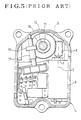
- Fig. 4 is a sectional view of a main portion of a conventional optical axis adjusting device for a front illumination lamp.
- Fig. 5 is a plan view showing an internal construction of the optical axis adjusting device shown in Fig. 4.
- reference numeral 1 denotes a lamp housing.
- the lamp housing 1 has a lens 2 attached to and covering a front opening of the lamp housing 1.
- a reflector 3 supported by the lamp housing 1 is tilted through a ball bearing, not shown.
- An optical axis adjusting unit 4 is also attached to the lamp housing 1.
- This optical axis adjusting unit 4 contains a motor 5.
- Reference numeral 6 denotes a center axis of a rotary shaft 7 (see Fig. 5) of the motor 5.
- a worm 8, shown in Fig. 5, is attached to the rotary shaft 5.
- the worm 8 is in mesh with a worm wheel 9 which is, in turn, rotationally driven by the worm 8.
- a female-thread is formed in an inner wall, which defines a center hole of the worm wheel 9, of the worm wheel 9.
- the female-thread is in engagement with a male-thread 11 formed on a drive rod 10.
- the drive rod 10 is reciprocated in an axial direction (forward and backward directions F and R in Fig. 4) in response to rotation of the worm wheel 9.
- the term "forward” refers to a direction in which the front illumination lamp projects a beam of light.
- a spherical end portion 12 is formed on a front end of the drive rod 10.
- the spherical end portion 12 is relatively rotatably connected to a bracket 14 of the reflector 3 through a mounting member 13. According to this arrangement, the reflector 3 is tilted in response to the reciprocative movement of the drive rod 10, so that the optical axis of the reflector 3 is adjusted.
- An aiming member 15 for initial adjustment is disposed on a rear end of the lamp housing 1.
- the aiming member 15 is rotatably supported by a bearing member 16.
- This conventional optical axis adjusting device for a front illumination lamp is designed such that when the aiming member 15 is manually turned with a tool, such as a driver, the drive rod 10 is turned in unison with the aiming member 15 and moved forwardly and backwardly under the effect of the male-thread 11. By doing this, an ex-factory basic adjustment (or aiming) is accomplished.
- the worm wheel 9 is not rotated because it is in mesh with the worm 8.
- Reference numeral 17 denotes a rotation angle detector for detecting a tilt angle of the reflector 3. Rotation of the worm wheel 9 is transmitted to the rotation angle detector 17 at a reduced speed.
- the reflector 3 is tiltably supported by the lamp housing 1 and driven by the optical axis adjusting unit 4 for tilting.
- another conventional optical axis adjusting device for a front illumination lamp in which a reflector 3 and a lamp housing 1 are integrally formed, the lamp housing 1 is tiltably supported by a vehicle body or the like, and the lamp housing 1 and the reflector 3 are tilted in unison.
- the related device comprises a drive rod being axially movable for tilting the related headlight.
- Said drive rod is integrally provided with a rack means which is engaged with a driving gear of a related driving means.
- a related positioning detecting means consists of a slide potentiometer extending parallel to the drive rod.
- An input member of said potentiometer consists of a first slide traveling along an opening in the potentiometer.
- a second slide sleeve means is connected integrally with said first slide via an appendix being integrally provided at said first slide.
- Said second slide means comprises a hole to receive an end portion of the drive rod so that the drive rod is in frictional contact with said slide and a lock screw is provided for locking said drive rod inside of said hole.
- said screw is released and the rod is displaced by the driving means via the above-mentioned rack means.
- the initial adjustment of the lamp can be carried out by choosing said lamp in an initial state.
- the second slide means is moved to place the appendix of the position detecting sensor in a position corresponding to said initial state and said screw is used to connect the rod with the second slide means in said position.
- the screw rod member is provided with an aiming member for use in manual adjustment. It is preferred that the screw rod member is operated to tilt a reflector disposed within a housing, a threaded portion is formed on a distal end portion of the screw rod member, a screw mounting member is turnably provided on the reflector, the threaded portion of the screw rod member is engaged with the screw mounting member, and a rear end portion of the screw rod member is rotatably supported by the housing.
- an annular flange is formed on the screw rod member, and an annular groove for engaging with the annular flange is formed in the forwardly/backwardly movable sleeve member. It is preferred that the stator is secured to the housing. Desirably, a reduction gear mechanism is disposed between the drive rod and the motor.
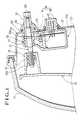
- Fig. 1 is a sectional view of a main portion of an optical axis adjusting device for a front illumination lamp.
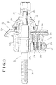
- Fig. 2 is a sectional view showing an internal construction of an optical axis adjusting unit shown in Fig. 1.
- reference numeral 20 denotes a lamp housing.
- the lamp housing 20 has a lens 21 attached to and covering a front opening portion of the lamp housing 20.
- a reflector 22 is tiltably supported by the lamp housing 20 through ball bearing, not shown.
- An optical axis adjusting unit 23 is also attached to the lamp housing 20.
- An optical axis of the light of the illumination lamp is tilted for adjustment in response to a tilting motion of the reflector 22.
- the reflector 22 is integrally formed with a bracket 24.
- a screw mounting member 25 is rotatably supported by the bracket 24.
- the screw mounting member 25 has a female-thread portion.
- a screw rod member 26 is in engagement with the screw mounting portion 25.
- Reference numeral 26a denotes a male-thread portion of the screw rod member 26.
- the screw rod member 26 and a drive rod 28 constitute a forwardly/backwardly movable sleeve member 27.
- the forwardly/backwardly movable member 27 is of a two-piece construction here.
- the screw rod member 26 is inserted into the forwardly/backwardly movable sleeve member 27.
- Detailed constructions of the forwardly/backwardly movable sleeve member 27 and the screw rod member 26 will be described later.
- the optical axis adjusting unit 23 will now be described.
- the optical axis adjusting unit 23 includes a casing 23a.
- a driving motor 29 for adjusting the tilting angle of the reflector 22 is disposed within the casing 23a as shown in Fig. 2.
- a worm 30 is mounted on an output shaft 29a of the driving motor 29 as shown in Fig. 3.
- Support shafts 29b and 29c are formed on the casing 23a.
- a cylindrical threaded member 31 is rotatably supported by the support shafts 29b and 29c.
- the cylindrical threaded member 31 includes a reduced diameter portion and an enlarged diameter portion.
- a worm wheel 31a is formed in the reduced diameter portion and a worm 31b is formed on the enlarged diameter portion.
- the worm wheel 31a is in mesh with the worm 30.
- the screw rod member 26 has an annular flange 26b formed on an intermediate portion thereof.
- a D-shaped portion is formed on a rear end portion 26c of the screw rod member 26.
- An aiming member 32 is fitted to the D-shaped portion.
- a guide hole 33 is formed in the aiming member 32, and the forwardly/backwardly movable sleeve member 27 is slidably engaged with the guide hole 33.
- An annular groove 27a is formed in the center of the forwardly/backwardly movable sleeve member 27, and a worm rack 27b is integrally formed on a lower part thereof.
- the worm rack 27b is in mesh with the worm 31b.
- the annular flange 26b is in engagement with the annular groove 27a.
- the screw rod member 26 is rotatable relative to the forwardly/backwardly movable sleeve member 27.
- the aiming member 32 is used for initial adjustment before the devices which are finished products are transported from the factory.
- the screw rod member 26 is moved forwardly and backwardly while being rotated. Since the worm rack 27b is in mesh with the worm 31b at that time, the forwardly/backwardly movable sleeve member 27 is not moved forwardly and backwardly in response to the forward and backward movement of the screw rod member 26.
- the worm 30, worm wheel 21a, and worm 31a constitute, as shown in Fig. 2, a reduction gear mechanism 34 for transmitting the rotation of the driving motor 29 to the forwardly/backwardly movable sleeve member 27 at a reduced speed.
- the worm rack 27b has a role for transforming the rotation of the reduction gear mechanism 34 to a linear motion.
- the rotation of the driving motor 29 is transmitted to the drive rod 28 through the reduction gear mechanism 34 and the worm rack 27b.
- the drive rod 28 is moved forwardly and backwardly in accordance with the normal/reverse rotation of the driving motor 29.
- a support member 27c is formed on the forwardly/backwardly movable sleeve member 27 as shown in Fig. 1.
- a movable element 35 is secured to the support member 27c.
- a stator 36 is secured within the casing 23a.
- the stator 36 is secured to a circuit board 37.
- the stator 36 is, for example, a resistor variable element.
- the movable element 35 is slidably in contact with the stator 36.
- the movable element 35 and the stator 36 constitute a position sensor 38 for detecting a forward/backward position of the drive rod 28.
- reference numeral 39 is a bearing portion for rotatably supporting the aiming member 32
- reference numeral 40 is a seal member
- reference numeral 41 is a connecting terminal for supply a power source to the circuit board 37.
- the forwardly/backwardly movable sleeve member 27 is moved forwardly and backwardly in response to the rotation of the driving motor 29.
- the screw rod member 26 is also moved forwardly and backwardly in unison with the forward and backward movement of the forwardly/backwardly movable sleeve member 27. By doing this, the reflector 22 is tilted through the screw mounting member 25.
- the control of the driving motor 29 is performed by switching operation from a driving seat of an automobile.
- the position of the drive rod 28 can be detected in real time, and the tilting angle of the reflector 22 can be calculated with high precision.
Landscapes
- Engineering & Computer Science (AREA)
- Mechanical Engineering (AREA)
- Lighting Device Outwards From Vehicle And Optical Signal (AREA)
- Non-Portable Lighting Devices Or Systems Thereof (AREA)
- Securing Globes, Refractors, Reflectors Or The Like (AREA)
Claims (7)
- Vorrichtung zur Einstellung der optischen Achse eines Frontscheinwerfers mit:einem Antriebsstab (28) und einem Motor (29), um den Antriebsstab (28) vorwärts und rückwärts zu bewegen, um die optische Achse des Frontscheinwerfers durch Vorwärts-/Rückwärtsbewegung des Antriebsstabes einzustellen;einem Positionserfassungssensor (38), der ein bewegbares Element (35) aufweist, das in der Lage ist, sich in Übereinstimmung mit der Vorwärts-/Rückwärtsbewegung des Antriebsstabes zu bewegen;und einem Stator (36) zur Erfassung einer vorwärts-/rückwärtigen Position des Antriebsstabes (28) durch Zusammenwirken mit dem bewegbaren Element (35);wobei der Antriebsstab (28) ein vorwärts-/rückwärts bewegbares Hülsenteil (27) aufweist, das durch die Drehung des Motors (29) veranlaßt wird, sich vorwärts/rückwärts zu bewegen, einem Spindelteil (26), das in das vorwärts-/rückwärts bewegbare Hülsenteil (27) eingesetzt und in Übereinstimmung mit der Vorwärts/Rückwärtsbewegung des vorwärts-/rückwärts bewegbaren Hülsenteiles (27) bewegbar ist, wobei das Spindelteil (26) relativ drehbar mit dem vorwärts-/rückwärts bewegbaren Hülsenteil (27) im Eingriff ist, und einer Eingriffseinrichtung (27b) zur Umwandlung der Drehung des Motors (29) in eine lineare Bewegung, die an dem vorwärts-/rückwärts bewegbaren Hülsenteil (27) ausgebildet ist, dadurch gekennzeichnet, daß die Eingriffseinrichtung eine Zahnstange (27b) ist, ausgebildet an dem vorwärts-/rückwärts bewegbaren Hülsenteil (27) und das bewegbare Element (35) an dem vorwärts-/rückwärts bewegbaren Hülsenteil (27) ausgebildet ist.
- Vorrichtung zur Einstellung der optischen Achse eines Frontscheinwerfers nach Anspruch 1, dadurch gekennzeichnet, daß ein Ringflansch (26b) an dem Spindelteil (26) ausgebildet ist und eine Ringnut (27a) in dem vorwärts-/rückwärts bewegbaren Hülsenteil (27) ausgebildet ist, um in den Ringflansch einzugreifen.
- Vorrichtung zur Einstellung der optischen Achse eines Frontscheinwerfers nach Anspruch 1 oder 2, dadurch gekennzeichnet, daß eine Untersetzungsgetriebevorrichtung (34) zwischen dem Antriebsstab (28) und dem Motor (29) angeordnet ist.
- Vorrichtung zur Einstellung der optischen Achse eines Frontscheinwerfers nach einem der Ansprüche 1 bis 3, dadurch gekennzeichnet, daß das Spindelteil (26) mit einem Richtteil (32) zur Benutzung in der manuellen Einstellung vorgesehen ist.
- Vorrichtung zur Einstellung der optischen Achse eines Frontscheinwerfers nach einem der Ansprüche 1 bis 4, dadurch gekennzeichnet, daß das Spindelteil (26) betätigt wird, um einen Reflektor (22), angebracht innerhalb eines Gehäuses (20), zu neigen.
- Vorrichtung zur Einstellung der optischen Achse eines Frontscheinwerfers nach einem der Ansprüche 1 bis 4, dadurch gekennzeichnet, daß ein Gewindeabschnitt an einem vorauslaufenden Endabschnitt des Spindelteiles (26) ausgebildet ist und ein Schraubenmontageteil (25) drehbar an dem Reflektor (22) vorgesehen ist, wobei der Gewindeabschnitt des Spindelteiles (26) in Eingriff ist mit dem Schraubenmontageteil (25), ein hinterer Endabschnitt des Spindelteiles (26) ist drehbar durch das Gehäuse (20) gelagert.
- Vorrichtung zur Einstellung der optischen Achse eines Frontscheinwerfers nach einem der Ansprüche 1 bis 4, dadurch gekennzeichnet, daß der Stator (36) an dem Gehäuse (20) befestigt ist.
Applications Claiming Priority (3)
| Application Number | Priority Date | Filing Date | Title |
|---|---|---|---|
| JP31062694A JP3161259B2 (ja) | 1994-12-14 | 1994-12-14 | 前照灯の光軸調整装置 |
| JP310626/94 | 1994-12-14 | ||
| JP31062694 | 1994-12-14 |
Publications (3)
| Publication Number | Publication Date |
|---|---|
| EP0716954A2 EP0716954A2 (de) | 1996-06-19 |
| EP0716954A3 EP0716954A3 (de) | 1997-03-19 |
| EP0716954B1 true EP0716954B1 (de) | 2001-09-05 |
Family
ID=18007528
Family Applications (1)
| Application Number | Title | Priority Date | Filing Date |
|---|---|---|---|
| EP95119647A Expired - Lifetime EP0716954B1 (de) | 1994-12-14 | 1995-12-13 | Vorrichtung zum Einstellen der optischen Achse eines Scheinwerfers |
Country Status (4)
| Country | Link |
|---|---|
| EP (1) | EP0716954B1 (de) |
| JP (1) | JP3161259B2 (de) |
| KR (1) | KR0173817B1 (de) |
| DE (1) | DE69522538T2 (de) |
Cited By (1)
| Publication number | Priority date | Publication date | Assignee | Title |
|---|---|---|---|---|
| CN101469839B (zh) * | 2007-12-24 | 2012-09-05 | 上海小糸车灯有限公司 | 一种用于汽车前照灯的调光执行器 |
Families Citing this family (7)
| Publication number | Priority date | Publication date | Assignee | Title |
|---|---|---|---|---|
| ITTO980401A1 (it) * | 1998-05-12 | 1999-11-12 | Magneti Marelli Spa | Dispositivo regolatore d'assetto per un faro di un veicolo. |
| JP3928687B2 (ja) * | 1999-09-30 | 2007-06-13 | 株式会社小糸製作所 | 車輌用前照灯のレベリング装置 |
| JP3887526B2 (ja) | 1999-09-30 | 2007-02-28 | 株式会社小糸製作所 | 車輌用前照灯のレベリング装置 |
| JP2001216818A (ja) | 2000-02-02 | 2001-08-10 | Ichikoh Ind Ltd | 自動車用前照灯における光軸調整装置 |
| JP4353241B2 (ja) | 2006-11-24 | 2009-10-28 | 市光工業株式会社 | 車両用前照灯のレベリング装置およびレベリング装置を備える車両用前照灯 |
| JP4831062B2 (ja) * | 2007-12-26 | 2011-12-07 | 市光工業株式会社 | 車両用前照灯のレベリング装置 |
| CN102700456A (zh) * | 2012-05-23 | 2012-10-03 | 常州星宇车灯股份有限公司 | 汽车前照灯外置调光电机装置 |
Family Cites Families (4)
| Publication number | Priority date | Publication date | Assignee | Title |
|---|---|---|---|---|
| EP0120442B1 (de) * | 1983-03-22 | 1987-12-09 | Ichikoh Industries Limited | Vorrichtung zur Regelung der Leuchtweite eines Kraftfahrzeugscheinwerfers |
| IT1237749B (it) * | 1989-12-29 | 1993-06-15 | Carello Spa | Proiettore orientabile per veicoli |
| DE9107346U1 (de) * | 1991-06-14 | 1992-10-08 | Robert Bosch Gmbh, 7000 Stuttgart | Vorrichtung zum Verstellen der Neigung von Scheinwerfern bei Kraftfahrzeugen |
| DE9407070U1 (de) * | 1994-04-28 | 1994-06-30 | Hella Kg Hueck & Co, 59557 Lippstadt | Haltevorrichtung für ein verschiebbares Abgriffelement eines Potentiometers einer elektrischen Verstelleinrichtung zur Verstellung eines Reflektors eines Fahrzeug-Scheinwerfers |
-
1994
- 1994-12-14 JP JP31062694A patent/JP3161259B2/ja not_active Expired - Fee Related
-
1995
- 1995-12-13 EP EP95119647A patent/EP0716954B1/de not_active Expired - Lifetime
- 1995-12-13 DE DE69522538T patent/DE69522538T2/de not_active Expired - Lifetime
- 1995-12-14 KR KR1019950049618A patent/KR0173817B1/ko not_active Expired - Fee Related
Cited By (1)
| Publication number | Priority date | Publication date | Assignee | Title |
|---|---|---|---|---|
| CN101469839B (zh) * | 2007-12-24 | 2012-09-05 | 上海小糸车灯有限公司 | 一种用于汽车前照灯的调光执行器 |
Also Published As
| Publication number | Publication date |
|---|---|
| EP0716954A2 (de) | 1996-06-19 |
| KR0173817B1 (ko) | 1999-02-18 |
| EP0716954A3 (de) | 1997-03-19 |
| JP3161259B2 (ja) | 2001-04-25 |
| DE69522538T2 (de) | 2002-07-11 |
| JPH08164789A (ja) | 1996-06-25 |
| KR960021849A (ko) | 1996-07-18 |
| DE69522538D1 (de) | 2001-10-11 |
Similar Documents
| Publication | Publication Date | Title |
|---|---|---|
| JP4761563B2 (ja) | 車輌用灯具及び車輌用灯具の光軸調整装置 | |
| US20080112179A1 (en) | Lighting device for vehicle | |
| EP1283534B1 (de) | Manuelle Eingabevorrichtung mit Kraftrückkopplungsfunktion | |
| US5070433A (en) | Headlight for a motor vehicle having an adjustable motor-driven reflector | |
| EP0716954B1 (de) | Vorrichtung zum Einstellen der optischen Achse eines Scheinwerfers | |
| GB2239513A (en) | Vehicle headlight | |
| US20050035261A1 (en) | Vehicle seat adjuster | |
| KR920004478B1 (ko) | 변속제어장치 | |
| JP2517487B2 (ja) | 前照灯の照射角度調整装置 | |
| GB2192052A (en) | Light focus driving lights for vehicles | |
| JPH0834064B2 (ja) | 車輌用前照灯の傾動装置 | |
| JPH0668992U (ja) | バックミラーの角度調整機構 | |
| JPH0229537B2 (de) | ||
| JPH083922Y2 (ja) | 配光可変型前照灯のレンズ駆動機構 | |
| JP2813854B2 (ja) | ヘッドランプレベリング機構 | |
| KR100873097B1 (ko) | 자동차용 전조등의 각도조정장치 | |
| JPS61202945A (ja) | 前照灯の光軸調整装置 | |
| JP4085451B2 (ja) | 自動車用前照灯の光軸調整装置 | |
| KR100543386B1 (ko) | 자동차용전조등의광축조정장치 | |
| WO2008047381A1 (en) | Headlamp adjuster for automobiles | |
| JPH0141622Y2 (de) | ||
| JPH0113641Y2 (de) | ||
| EP0793076B1 (de) | Vorrichtung zur Bestimmung der Ausgangswellenposition eines Stellgliedes | |
| JP2534536B2 (ja) | 前照灯装置 | |
| JPS61200044A (ja) | 前照灯の光軸調整装置 |
Legal Events
| Date | Code | Title | Description |
|---|---|---|---|
| PUAI | Public reference made under article 153(3) epc to a published international application that has entered the european phase |
Free format text: ORIGINAL CODE: 0009012 |
|
| 17P | Request for examination filed |
Effective date: 19951213 |
|
| AK | Designated contracting states |
Kind code of ref document: A2 Designated state(s): DE FR GB |
|
| PUAL | Search report despatched |
Free format text: ORIGINAL CODE: 0009013 |
|
| AK | Designated contracting states |
Kind code of ref document: A3 Designated state(s): DE FR GB |
|
| 17Q | First examination report despatched |
Effective date: 19981130 |
|
| GRAG | Despatch of communication of intention to grant |
Free format text: ORIGINAL CODE: EPIDOS AGRA |
|
| GRAG | Despatch of communication of intention to grant |
Free format text: ORIGINAL CODE: EPIDOS AGRA |
|
| GRAH | Despatch of communication of intention to grant a patent |
Free format text: ORIGINAL CODE: EPIDOS IGRA |
|
| GRAH | Despatch of communication of intention to grant a patent |
Free format text: ORIGINAL CODE: EPIDOS IGRA |
|
| GRAA | (expected) grant |
Free format text: ORIGINAL CODE: 0009210 |
|
| AK | Designated contracting states |
Kind code of ref document: B1 Designated state(s): DE FR GB |
|
| REF | Corresponds to: |
Ref document number: 69522538 Country of ref document: DE Date of ref document: 20011011 |
|
| REG | Reference to a national code |
Ref country code: GB Ref legal event code: IF02 |
|
| ET | Fr: translation filed | ||
| PLBE | No opposition filed within time limit |
Free format text: ORIGINAL CODE: 0009261 |
|
| STAA | Information on the status of an ep patent application or granted ep patent |
Free format text: STATUS: NO OPPOSITION FILED WITHIN TIME LIMIT |
|
| 26N | No opposition filed | ||
| PGFP | Annual fee paid to national office [announced via postgrant information from national office to epo] |
Ref country code: GB Payment date: 20091209 Year of fee payment: 15 Ref country code: FR Payment date: 20091221 Year of fee payment: 15 |
|
| PGFP | Annual fee paid to national office [announced via postgrant information from national office to epo] |
Ref country code: DE Payment date: 20091222 Year of fee payment: 15 |
|
| GBPC | Gb: european patent ceased through non-payment of renewal fee |
Effective date: 20101213 |
|
| REG | Reference to a national code |
Ref country code: FR Ref legal event code: ST Effective date: 20110831 |
|
| PG25 | Lapsed in a contracting state [announced via postgrant information from national office to epo] |
Ref country code: FR Free format text: LAPSE BECAUSE OF NON-PAYMENT OF DUE FEES Effective date: 20110103 |
|
| PG25 | Lapsed in a contracting state [announced via postgrant information from national office to epo] |
Ref country code: DE Free format text: LAPSE BECAUSE OF NON-PAYMENT OF DUE FEES Effective date: 20110701 Ref country code: GB Free format text: LAPSE BECAUSE OF NON-PAYMENT OF DUE FEES Effective date: 20101213 |
|
| REG | Reference to a national code |
Ref country code: DE Ref legal event code: R119 Ref document number: 69522538 Country of ref document: DE Effective date: 20110701 |