EP0717271A2 - Système de capteur de pesage - Google Patents
Système de capteur de pesage Download PDFInfo
- Publication number
- EP0717271A2 EP0717271A2 EP95105851A EP95105851A EP0717271A2 EP 0717271 A2 EP0717271 A2 EP 0717271A2 EP 95105851 A EP95105851 A EP 95105851A EP 95105851 A EP95105851 A EP 95105851A EP 0717271 A2 EP0717271 A2 EP 0717271A2
- Authority
- EP
- European Patent Office
- Prior art keywords
- support
- load cell
- pendulum
- pendulum support
- cell arrangement
- Prior art date
- Legal status (The legal status is an assumption and is not a legal conclusion. Google has not performed a legal analysis and makes no representation as to the accuracy of the status listed.)
- Granted
Links
- 230000002093 peripheral effect Effects 0.000 claims description 4
- 238000007789 sealing Methods 0.000 claims 2
- 238000010276 construction Methods 0.000 abstract 1
- 238000005303 weighing Methods 0.000 description 8
- 238000003466 welding Methods 0.000 description 2
- 238000011109 contamination Methods 0.000 description 1
- 230000001419 dependent effect Effects 0.000 description 1
- 238000011156 evaluation Methods 0.000 description 1
- 238000009434 installation Methods 0.000 description 1
- 239000002184 metal Substances 0.000 description 1
- 238000004080 punching Methods 0.000 description 1
- 238000005476 soldering Methods 0.000 description 1
Images
Classifications
-
- G—PHYSICS
- G01—MEASURING; TESTING
- G01G—WEIGHING
- G01G3/00—Weighing apparatus characterised by the use of elastically-deformable members, e.g. spring balances
- G01G3/12—Weighing apparatus characterised by the use of elastically-deformable members, e.g. spring balances wherein the weighing element is in the form of a solid body stressed by pressure or tension during weighing
- G01G3/14—Weighing apparatus characterised by the use of elastically-deformable members, e.g. spring balances wherein the weighing element is in the form of a solid body stressed by pressure or tension during weighing measuring variations of electrical resistance
- G01G3/1402—Special supports with preselected places to mount the resistance strain gauges; Mounting of supports
- G01G3/1408—Special supports with preselected places to mount the resistance strain gauges; Mounting of supports the supports being of the column type, e.g. cylindric
-
- G—PHYSICS
- G01—MEASURING; TESTING
- G01G—WEIGHING
- G01G19/00—Weighing apparatus or methods adapted for special purposes not provided for in the preceding groups
- G01G19/02—Weighing apparatus or methods adapted for special purposes not provided for in the preceding groups for weighing wheeled or rolling bodies, e.g. vehicles
- G01G19/021—Weighing apparatus or methods adapted for special purposes not provided for in the preceding groups for weighing wheeled or rolling bodies, e.g. vehicles having electrical weight-sensitive devices
-
- G—PHYSICS
- G01—MEASURING; TESTING
- G01G—WEIGHING
- G01G21/00—Details of weighing apparatus
- G01G21/23—Support or suspension of weighing platforms
Definitions
- the invention relates to a load cell arrangement with a pendulum support load cell, with at least one support element assigned to one end of the pendulum support and with a device comprising associated elements on the pendulum support and support element in order to limit the rotation of the pendulum support about its axis.
- Load cell arrangements of this type are used, inter alia, in weighing devices, platform scales and, in particular, in weighing platforms for weighing vehicles.
- Several load cell arrangements each with a pendulum support load cell, are arranged between the weighing platform and a foundation.
- the weighing platform can be moved horizontally within permitted limits, so that during these movements the load cells perform pendulum movements which generally do not exceed an angular range of 10 degrees.
- the load cells are therefore exposed to both vertical and transverse forces. This can result in the load cells being forced onto undesired rotary movements about their axis, which under certain circumstances can lead to the wiring being torn off.
- a rotational movement of the pendulum support about its axis is limited by assigning an axially parallel extending tab fastened near the pendulum support end to a screw which is screwed radially into the support element such that the screw has a long slot in the tab reaches through with play.
- a bell-shaped part is provided at the end of the pendulum support, which bulges over the support point and which has four circumferential recesses distributed over the circumference and extending from the edge of the bell-shaped part.
- a load cell arrangement is known from EP patent 0 419 784, in which one end of the pendulum support has a non-circular shape, this end region also being designed in the form of a segment of a straight cylinder. This end region is arranged in a correspondingly designed recess in the support element. It is further disclosed to provide one end of the pendulum support with transversely extending pin-shaped extensions which engage in corresponding recesses in the support element. Furthermore, load cell arrangements are disclosed in this US patent, in which the housing surrounding the pendulum support has extensions which are arranged between two webs which are fixedly arranged for support.
- the invention is therefore based on the object of providing a load cell arrangement with a rotation limiting device which is compact and simple and inexpensive.
- the pendulum support is provided at its end region with a collar which has a recess with stop faces which cooperate with an element which is fixedly arranged on the support element.
- the collar can be produced very simply as a stamped or flame-cut sheet metal part and can be connected to the end of the pendulum support, for example by welding or soldering.
- the collar can be ring-shaped and produced as a turned part will. The recesses can be made before parting the ring or on the finished ring part.
- the pin-shaped, axially parallel attached to the support element is arranged close to the support surface for the end of the pendulum support.
- a bellows can be attached to the outer diameter of the support element and housing, which sealingly surrounds the support point and the rotation limiting device.
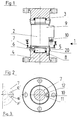
- the pendulum support load cell 2 has a pendulum support 6 and a housing 9 which tightly surrounds the pendulum support 6.
- the pendulum support 6 is provided in a manner not shown with strain gauges for detecting load-dependent deformations due to the load to be weighed.
- the strain gauges are connected to a signal processing circuit housed in the housing 9, which in turn is provided with a connection unit 10 for an evaluation device.
- the two end regions of the pendulum support 6 are spherical and are supported in a sealed manner in recesses in the support elements 3 and 4.
- the pendulum support 6 z. B. be designed self-righting or not self-righting, as this z. B. is described in more detail in EP 0 315 846 A1.
- the rotation limiting device 5 comprises the element 7 fastened to the pendulum support 6, designed as a collar and extending in a cross-sectional plane, which has a peripheral recess 10 with stop surfaces 11 and 12 on the outside diameter.
- the stop surfaces 11 and 12 run approximately radially outwards.
- the element 7 is made by punching out of a sheet and by z. B. welding attached to the pendulum support 6.
- 3 shows an embodiment in which, instead of the circumferential recess 10, an elongated hole-shaped recess 10 'extending along a circular line section is provided, the stop surfaces 11', 12 'being located at the ends of the elongated hole-shaped recess 10'.
- the rotation limiting device 5 further comprises the pin-shaped element 8 which is fastened to the support element 4 and extends axially parallel to the pendulum support axis.
- the element 8 is a cylindrical pin inserted into a blind bore of the support element 4.
- the length of the pin-shaped element 8 and the position of the collar on the end region of the pendulum support 6 are chosen so that even with maximum inclination of the pendulum support 6 the collar remains in engagement with the pin-shaped element 8 on the one hand and on the other hand does not come into contact with the end face of the support element 4 is coming. Likewise, the pin-shaped element 8 does not come into contact with the end face of the housing 9.
- the peripheral recess 10 or the slot-shaped recess 10 surrounds the pin-shaped element 8 with such play that an inclination of the pendulum support 6 in space, ie an inclination with the Pendulum support axis on a cone jacket around the support point is possible in the support element 4 without hindrance by contact between the collar and the pin-shaped element 8.
- Such a pendulum movement in space has an angle of less than 10 degrees.
- the rotary movement device 5 can of course be provided on its upper end area instead of on the lower end area of the pendulum support 6 and then interacts with the upper support element 3.
- an elastic bellows 20 is provided in the exemplary embodiment shown, the ends of which are mounted on the support element 4 and on the housing 9 of the pendulum support 6.
- the load cell arrangement according to the invention can, for. B. used in platform scales or weighing platforms for weighing vehicles or for container weighing; Possible applications are described and described in detail in the brochure "Installation of load cells” from Hottinger Baldwin Messtechnik GmbH.
Landscapes
- Physics & Mathematics (AREA)
- General Physics & Mathematics (AREA)
- Measurement Of Force In General (AREA)
- Micro-Organisms Or Cultivation Processes Thereof (AREA)
- Pivots And Pivotal Connections (AREA)
Applications Claiming Priority (2)
| Application Number | Priority Date | Filing Date | Title |
|---|---|---|---|
| DE9419696U DE9419696U1 (de) | 1994-12-13 | 1994-12-13 | Wägezellenanordnung |
| DE9419696U | 1994-12-13 |
Publications (3)
| Publication Number | Publication Date |
|---|---|
| EP0717271A2 true EP0717271A2 (fr) | 1996-06-19 |
| EP0717271A3 EP0717271A3 (fr) | 1997-06-04 |
| EP0717271B1 EP0717271B1 (fr) | 2001-08-08 |
Family
ID=6917163
Family Applications (1)
| Application Number | Title | Priority Date | Filing Date |
|---|---|---|---|
| EP95105851A Expired - Lifetime EP0717271B1 (fr) | 1994-12-13 | 1995-04-19 | Système de capteur de pesage |
Country Status (3)
| Country | Link |
|---|---|
| US (1) | US5566575A (fr) |
| EP (1) | EP0717271B1 (fr) |
| DE (3) | DE9419696U1 (fr) |
Cited By (1)
| Publication number | Priority date | Publication date | Assignee | Title |
|---|---|---|---|---|
| CN102426048A (zh) * | 2011-09-13 | 2012-04-25 | 中航电测仪器股份有限公司 | 弯板式传感器轴重称 |
Families Citing this family (9)
| Publication number | Priority date | Publication date | Assignee | Title |
|---|---|---|---|---|
| US4566251A (en) * | 1985-01-07 | 1986-01-28 | Ex-Cell-O Corporation | Carton forming, sterilizing, filling and sealing machine |
| DE19625821C1 (de) * | 1996-06-28 | 1997-12-18 | Johannes Borngaesser | Standfuß für eine Meßzelle |
| US8058493B2 (en) * | 2003-05-21 | 2011-11-15 | Baker Hughes Incorporated | Removing amines from hydrocarbon streams |
| DE102008064169B4 (de) | 2008-12-22 | 2013-07-18 | Hottinger Baldwin Messtechnik Gmbh | Wägezelle |
| DE102010014152B4 (de) * | 2010-04-07 | 2015-12-24 | Hottinger Baldwin Messtechnik Gmbh | Wägezelle |
| CN103674212B (zh) * | 2012-09-19 | 2017-11-28 | 梅特勒-托利多有限公司 | 测力计称重模块 |
| DE102017128078B4 (de) * | 2017-11-28 | 2022-09-01 | Minebea Intec GmbH | Verdrehsensor für eine Wägezelle |
| DE102019129558A1 (de) * | 2019-11-01 | 2021-05-06 | Minebea Intec GmbH | Verdrehsicherung für eine Wägezelle |
| CN118500600B (zh) * | 2024-04-18 | 2025-05-02 | 中建宏达建筑有限公司 | 一种可称重安全智能液压防护平台及其施工方法 |
Family Cites Families (13)
| Publication number | Priority date | Publication date | Assignee | Title |
|---|---|---|---|---|
| US2488348A (en) * | 1944-05-01 | 1949-11-15 | Baldwin Locomotive Works | Electric load weighing device |
| US2775887A (en) * | 1953-06-11 | 1957-01-01 | Baldwin Lima Hamilton Corp | Load cell type dynamometer with overload protection means |
| US2901235A (en) * | 1956-11-21 | 1959-08-25 | Toledo Scale Corp | Platform supporting structure for weighing scales |
| US3407891A (en) * | 1966-11-25 | 1968-10-29 | Fairbanks Morse Inc | Load cell mounting of load receiver means as a scale weighbridge |
| FR2208521A5 (fr) * | 1972-11-28 | 1974-06-21 | Trayvou Sa | |
| US4493220A (en) * | 1982-11-23 | 1985-01-15 | Advanced Mechanical Technology, Inc. | Force measuring platform and load cell therefor using strain gages to measure shear forces |
| US4475610A (en) * | 1983-03-24 | 1984-10-09 | Timex Mecial Products Corporation | Levered scale with strain gauge tension link |
| US4581948A (en) * | 1984-02-07 | 1986-04-15 | World Wide Weighing, Inc. | Load cell assembly for use in a vehicle platform scale |
| US4804053B1 (en) * | 1987-11-10 | 1996-09-03 | Flintab Ab | Rocker pin load cell |
| US4815547A (en) * | 1987-11-30 | 1989-03-28 | Toledo Scale Corporation | Load cell |
| US4932253A (en) * | 1989-05-02 | 1990-06-12 | Mccoy James N | Rod mounted load cell |
| US4955441A (en) * | 1989-09-26 | 1990-09-11 | Toledo Scale Corporation | Load cell mounting for rotational control |
| US5090493A (en) * | 1990-10-29 | 1992-02-25 | International Road Dynamics Inc. | Load cells and scales therefrom |
-
1994
- 1994-12-13 DE DE9419696U patent/DE9419696U1/de not_active Expired - Lifetime
-
1995
- 1995-04-19 EP EP95105851A patent/EP0717271B1/fr not_active Expired - Lifetime
- 1995-04-19 DE DE59509487T patent/DE59509487D1/de not_active Expired - Lifetime
- 1995-04-22 DE DE19514892A patent/DE19514892A1/de not_active Withdrawn
- 1995-06-06 US US08/465,732 patent/US5566575A/en not_active Expired - Lifetime
Cited By (1)
| Publication number | Priority date | Publication date | Assignee | Title |
|---|---|---|---|---|
| CN102426048A (zh) * | 2011-09-13 | 2012-04-25 | 中航电测仪器股份有限公司 | 弯板式传感器轴重称 |
Also Published As
| Publication number | Publication date |
|---|---|
| EP0717271A3 (fr) | 1997-06-04 |
| US5566575A (en) | 1996-10-22 |
| DE19514892A1 (de) | 1996-06-20 |
| EP0717271B1 (fr) | 2001-08-08 |
| DE59509487D1 (de) | 2001-09-13 |
| DE9419696U1 (de) | 1995-02-02 |
Similar Documents
| Publication | Publication Date | Title |
|---|---|---|
| DE3509128C1 (de) | Lagerring | |
| EP0351006B1 (fr) | Transducteur de pression ou de force utilisant un ressort circulaire à symétrie axiale | |
| DE69825843T2 (de) | Vorrichtung zur Messung des Axialschubs in einer drehenden Welle | |
| DE1929478B2 (de) | Piezoelektrische messzelle | |
| EP0717271B1 (fr) | Système de capteur de pesage | |
| DE2027119C3 (de) | Kugelgelenkverbindung zwischen einer Lastaufnahmeplattform und Druckmeßzellen einer elektrischen Waage | |
| DE3026352C2 (fr) | ||
| AT394112B (de) | Druckaufnehmer | |
| DE10224199A1 (de) | Kraft-Messdose | |
| EP0987532B1 (fr) | Dispositif de mesure pour la détermination du couple de serrage total, du moment de friction d'une tête de vis et de la force de précontrainte d'une connexion à vis serrée | |
| EP0338325B1 (fr) | Dispositif de mesure de force du type d'anneau à torsion | |
| DE3625842A1 (de) | Druckmesszelle | |
| DE10139524A1 (de) | Vorrichtung zur Messung von Belastungen an rotierenden Bauteilen | |
| DE3342817C2 (de) | Meßnabe | |
| DE2631698C2 (de) | Kraftmeßwandler | |
| EP0229225B1 (fr) | Dispositif pour mesurer le niveau dans un récipient | |
| EP0836033B1 (fr) | Support pour une unité motrice vibratoire | |
| DE2158626A1 (de) | Zweiaxialer Kraftsensor für die Nabe von Steuerradlenkungen, insbesondere bei Flugzeugen | |
| EP0837002B1 (fr) | Boítier à applications industrielles | |
| EP0800064A2 (fr) | Capteur de pesage de forme allongé | |
| DE102018113771B4 (de) | Messvorrichtung zur Ermittlung von Zug- und Druckkräften, insbesondere Wägezelle | |
| DE102016010546B3 (de) | Drehmomentsensor mit axialem Anschlagelement | |
| DE19539581B4 (de) | Universalgelenk mit Feder-Viergelenken | |
| DE2909164A1 (de) | Kraftaufnehmer zur messung von auf einen pruefkoerper einwirkenden kraeften | |
| DE69309240T2 (de) | Taststiftvorrichtung, insbesondere für Kopiermaschinen |
Legal Events
| Date | Code | Title | Description |
|---|---|---|---|
| PUAI | Public reference made under article 153(3) epc to a published international application that has entered the european phase |
Free format text: ORIGINAL CODE: 0009012 |
|
| AK | Designated contracting states |
Kind code of ref document: A2 Designated state(s): DE FR GB IT NL |
|
| PUAL | Search report despatched |
Free format text: ORIGINAL CODE: 0009013 |
|
| AK | Designated contracting states |
Kind code of ref document: A3 Designated state(s): DE FR GB IT NL |
|
| 17P | Request for examination filed |
Effective date: 19970710 |
|
| 17Q | First examination report despatched |
Effective date: 19990825 |
|
| GRAG | Despatch of communication of intention to grant |
Free format text: ORIGINAL CODE: EPIDOS AGRA |
|
| GRAG | Despatch of communication of intention to grant |
Free format text: ORIGINAL CODE: EPIDOS AGRA |
|
| GRAH | Despatch of communication of intention to grant a patent |
Free format text: ORIGINAL CODE: EPIDOS IGRA |
|
| GRAH | Despatch of communication of intention to grant a patent |
Free format text: ORIGINAL CODE: EPIDOS IGRA |
|
| GRAA | (expected) grant |
Free format text: ORIGINAL CODE: 0009210 |
|
| AK | Designated contracting states |
Kind code of ref document: B1 Designated state(s): DE FR GB IT NL |
|
| GBT | Gb: translation of ep patent filed (gb section 77(6)(a)/1977) |
Effective date: 20010808 |
|
| REF | Corresponds to: |
Ref document number: 59509487 Country of ref document: DE Date of ref document: 20010913 |
|
| ET | Fr: translation filed | ||
| REG | Reference to a national code |
Ref country code: GB Ref legal event code: IF02 |
|
| PG25 | Lapsed in a contracting state [announced via postgrant information from national office to epo] |
Ref country code: GB Free format text: LAPSE BECAUSE OF NON-PAYMENT OF DUE FEES Effective date: 20020419 |
|
| PLBE | No opposition filed within time limit |
Free format text: ORIGINAL CODE: 0009261 |
|
| STAA | Information on the status of an ep patent application or granted ep patent |
Free format text: STATUS: NO OPPOSITION FILED WITHIN TIME LIMIT |
|
| 26N | No opposition filed | ||
| GBPC | Gb: european patent ceased through non-payment of renewal fee |
Effective date: 20020419 |
|
| PGFP | Annual fee paid to national office [announced via postgrant information from national office to epo] |
Ref country code: DE Payment date: 20140630 Year of fee payment: 20 Ref country code: FR Payment date: 20140429 Year of fee payment: 20 Ref country code: NL Payment date: 20140429 Year of fee payment: 20 Ref country code: IT Payment date: 20140428 Year of fee payment: 20 |
|
| REG | Reference to a national code |
Ref country code: DE Ref legal event code: R071 Ref document number: 59509487 Country of ref document: DE |
|
| REG | Reference to a national code |
Ref country code: NL Ref legal event code: V4 Effective date: 20150419 |