EP0717335A2 - Dispositif de restriction pour le mouvement d'une pédale dans une machine de contruction - Google Patents
Dispositif de restriction pour le mouvement d'une pédale dans une machine de contruction Download PDFInfo
- Publication number
- EP0717335A2 EP0717335A2 EP95402126A EP95402126A EP0717335A2 EP 0717335 A2 EP0717335 A2 EP 0717335A2 EP 95402126 A EP95402126 A EP 95402126A EP 95402126 A EP95402126 A EP 95402126A EP 0717335 A2 EP0717335 A2 EP 0717335A2
- Authority
- EP
- European Patent Office
- Prior art keywords
- restricting
- operation pedal
- pedal
- stepping
- tool member
- Prior art date
- Legal status (The legal status is an assumption and is not a legal conclusion. Google has not performed a legal analysis and makes no representation as to the accuracy of the status listed.)
- Withdrawn
Links
- 230000010355 oscillation Effects 0.000 claims abstract description 43
- 230000007935 neutral effect Effects 0.000 claims description 2
- 230000001429 stepping effect Effects 0.000 description 25
- 230000002452 interceptive effect Effects 0.000 description 6
- 230000002093 peripheral effect Effects 0.000 description 2
- 230000004308 accommodation Effects 0.000 description 1
- 238000010276 construction Methods 0.000 description 1
- 230000002542 deteriorative effect Effects 0.000 description 1
- 230000002708 enhancing effect Effects 0.000 description 1
- 230000037431 insertion Effects 0.000 description 1
- 238000003780 insertion Methods 0.000 description 1
Images



Classifications
-
- G—PHYSICS
- G05—CONTROLLING; REGULATING
- G05G—CONTROL DEVICES OR SYSTEMS INSOFAR AS CHARACTERISED BY MECHANICAL FEATURES ONLY
- G05G1/00—Controlling members, e.g. knobs or handles; Assemblies or arrangements thereof; Indicating position of controlling members
- G05G1/30—Controlling members actuated by foot
- G05G1/48—Non-slip pedal treads; Pedal extensions or attachments characterised by mechanical features only
- G05G1/483—Non-slip treads; Pedal extensions or attachments characterised by mechanical features only
-
- G—PHYSICS
- G05—CONTROLLING; REGULATING
- G05G—CONTROL DEVICES OR SYSTEMS INSOFAR AS CHARACTERISED BY MECHANICAL FEATURES ONLY
- G05G1/00—Controlling members, e.g. knobs or handles; Assemblies or arrangements thereof; Indicating position of controlling members
- G05G1/30—Controlling members actuated by foot
- G05G1/44—Controlling members actuated by foot pivoting
- G05G1/445—Controlling members actuated by foot pivoting about a central fulcrum
-
- G—PHYSICS
- G05—CONTROLLING; REGULATING
- G05G—CONTROL DEVICES OR SYSTEMS INSOFAR AS CHARACTERISED BY MECHANICAL FEATURES ONLY
- G05G5/00—Means for preventing, limiting or returning the movements of parts of a control mechanism, e.g. locking controlling member
- G05G5/005—Means for preventing, limiting or returning the movements of parts of a control mechanism, e.g. locking controlling member for preventing unintentional use of a control mechanism
-
- G—PHYSICS
- G05—CONTROLLING; REGULATING
- G05G—CONTROL DEVICES OR SYSTEMS INSOFAR AS CHARACTERISED BY MECHANICAL FEATURES ONLY
- G05G5/00—Means for preventing, limiting or returning the movements of parts of a control mechanism, e.g. locking controlling member
- G05G5/04—Stops for limiting movement of members, e.g. adjustable stop
Definitions
- the present invention relates to a stepping restricting device for an operation pedal in a working machine, such as a hydraulic shovel.
- Working machines such is hydraulic shovels, of the type which are constructed such that a working portion thereof is actuated on the basis of the stepping operation of an operation pedal disposed in front of an operator seat are known. While some operation pedals are for general use, others are used for optionally mounted attachments. Where such an attachment is not mounted or used, it is desirable that the operation pedal be locked. Where an attachment is mounted, a number of actuations of the working portion may differ depending on the type of attachment. Some attachments require change-over between a state where only the forward stepping is possible and a state where both forward and backward steppings are possible.
- Fig. 9 illustrates a conventional mechanism for performing such a change-over operation.
- an operation pedal 14 is provided in such a manner that it can be oscillated forward and backward about an oscillation axis 18a.
- a pedal support frame 27 having a through-hole 27b for full restriction and a through-hole 27c for half restriction protrudes from a machine body.
- a pedal frame 16 of the operation pedal 14 has a through-hole 16b for full restriction and an elongated hole 16c for half restriction.
- a restricting pin 28 is passed through the fully-restricting through-holes 16b and 27b.
- the restricting pin 28 is passed through the half-restricting hole 27c and the elongated hole 16c.
- the restricting pin 28 is passed through an accommodation hole 27a formed in the pedal support frame 27.
- the above-described change-over mechanism has problems in that change-over operation of the restricting pin 28 is troublesome and complicated, in that a pin 28a or a screw 28b for preventing release of the restricting pin 28 may be removed or lost, and in that the restricting pin 28 may also be lost when a chain 29 for connecting the restricting pin 28 to the pedal support frame 27 is cut.
- insertion and removal of the restricting pin 28 are conducted in front of the pedal where there is only a small space in the front portion of the cab, thus deteriorating workability.
- an object of the present invention is to provide an operation pedal stepping restricting device for restricting a stepping operation of an operation pedal in a working machine constructed such that a working portion is actuated on the basis of the stepping operation of the operation pedal disposed in front of an operator seat.
- the restricting device comprises an operation tool member which can be oscillated between a restricting position and a non-restricting position, and a restricting portion which does not interfere with the operation tool member at the non-restricting position but interferes with the operation tool member at the restricting position to restrict oscillation of the operation pedal.
- a hydraulic shovel 1 includes a crawler type lower travel body 2, an upper swivel body 3 turnably supported on the lower travel body 2, a working portion 4 mounted on the front of the upper swivel body 3, and so on. These components are hydraulically actuated on the basis of the power of an engine.
- the basic construction of each of these components is a known one.
- the working portion 4 includes a boom 5 whose proximal portion is supported on the upper swivel body 3 in such a manner that it can be oscillated up and down, an arm 6 supported on the distal end portion of the boom 5 in such a manner that it can be oscillated forward and backward and so on.
- Any of various attachments including bucket, a crusher, a grapple and a hammer, can be mounted on the distal end portion of the arm 6.
- a grapple 7 is mounted as the attachment.
- a cab 8 disposed in the upper swivel body 3 are provided various hydraulic operation tools, including right and left travelling levers 9R and 9L and right and left travelling pedals 10R and 10L used for travelling operations of the lower travel body 2, and right and left control levers 11R and 11L used for both swivel operation of the upper swivel body 3 and operations of the boom 5 and arm 6, and various operation units, such as an operator seat 12 and a monitor panel 13.
- an operation pedal 14 used for actuating a hydraulic actuator (not shown) for the grapple 7 is provided in front of the operator seat 12. The present invention is carried out in the operation pedal 14.
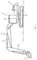
- the operation pedal 14 is made up of a pedal rubber 15, a pedal frame 16 and so on.
- a bottom surface portion of the pedal frame 16 is fixed, by bolts 18b, to an upper surface portion of an valve assembly 18 mounted in such a manner that it passes through a cab floor 17, in such a manner that it can be oscillated forward or backward about an oscillation axis 18a so that the pedal can be stepped forward or backward from a neutral position where the bottom surface portion of the pedal frame 16 is substantially parallel to the cab floor 17.
- a pilot valve (not shown) assembled in the valve assembly 18 is changed over according to the forward or backward stepping operation of the operation pedal 1, whereby an oil is supplied to the hydraulic actuator for the grapple 7 to operate the hydraulic actuator.
- a restricting device 19 for restricting the stepping operation of the operation pedal 14 is used when an attachment A (which may be a bucket actuated on the basis of the operation of the controller lever 11), which does not require the stepping operation of the operation pedal 14, is mounted in place of the grapple 7 or when the pilot valve has only one changing-over operation portion to be changed over by the operation pedal 14 and thus an attachment B (which may be a hydraulic hammer) mounted in place of the grapple 7 requires only the forward stepping of the operation pedal 14.
- an attachment A which may be a bucket actuated on the basis of the operation of the controller lever 11
- an attachment B which may be a hydraulic hammer mounted in place of the grapple 7 requires only the forward stepping of the operation pedal 14.
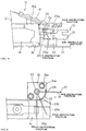
- the restricting device 19 is made up of a restricting member 20 provided on the side of the operation pedal 14, an oscillation lever 21 (corresponding to an operation tool member according to the present invention) provided on the side of the cab floor 17, a positioning member 22, a lock bolt and so on, as will be described later.
- the restricting member 20 has substantially a U-shaped form having a long upper piece 20a (corresponding to a first restricting portion according to the present invention) and a short lower piece 20b (corresponding to a second restricting portion according to the present invention).
- An upper portion of the upper piece 20a is fixed to a flange portion 16a formed at the rear end of the bottom portion of the pedal frame 16 in a state wherein an open side of the restricting member 20 is directed in a backward direction (toward the operator seat 12).
- a base frame 24 is disposed below the restricting member 20.
- the base frame 24 is fixed to the cab floor 17 through washers 24a and bolts 24b.
- a shaft tube portion 25 is provided upright from the base frame 24 in such a manner that the axis is directed in a vertical direction.
- a boss tube portion 26 is fitted on the outer peripheral portion of the shaft tube portion 25 in such a manner as to be rotatable about the axis of the shaft tube portion 25 and movable up and down.
- the proximal end portion of the oscillation lever 21 is fixed to the boss tube portion 26 so that the oscillation lever 21 can be oscillated about the shaft tube portion 25.
- An interfering piece 21a for interfering with the restricting member 20 provided on the side of the operation pedal 14 is formed at the distal end portion of the oscillation lever 21.
- the oscillation lever 21 When the oscillation lever 21 is positioned at a fully-restricting position where the distal end portion thereof is directed sideways, the interfering piece 21a is fitted between the upper and lower pieces 20a and 20b of the restricting member 20 and interferes with the bottom surface of the upper piece 20a and the upper surface of the lower piece 20b, whereby the forward and rearward steppings of the operation pedal 14 are restricted (see Fig. 6).
- the interfering piece 21a interferes with the bottom surface of the upper piece 20a but does not interfere with the short lower piece 20b, whereby the backward operation of the operation pedal 14 is restricted while the forward operation thereof is allowed for (see Fig. 7).
- the positioning member 22 for positioning the oscillation lever 21 at the fully-restricting position, the half-restricting position and non-restricting position is provided upward from the base frame 24 in an arc shape along the oscillation locus of the oscillator lever 21.
- the positioning member 22 has positioning recessed grooves 22a, 22b and 22c with which the lower portion of the oscillator lever 21 can engage at the fully-restricting position, the half-restricting position and the non-restricting position, respectively.
- the locking bolt 23 (corresponding to the locking member according to the present invention) is screwed into a threaded hole 25a cut into an inner peripheral portion of the shaft tube portion 25 in such a manner as to be movable up and down.
- a flange portion 23a is provided at the upper end portion of the locking bolt 23 above the boss tube portion 26 so as to allow for upward and downward movement of the oscillation lever 21 by a distance corresponding to a clearance S between the upper end of the boss tube portion 26 and the bottom surface of the flange portion 23a.
- the oscillation lever 21 can be oscillated freely to either of the fully-restricting position, the half-restricting position and the non-restricting position without the positioning member 22 interfering with the oscillation lever 21 by moving the locking bolt 23 up until the clearance S becomes greater than the depth of the positioning recessed grooves 22a, 22b and 22c and then by moving the oscillation lever 21 up until the lower end thereof is located above the upper end of the positioning member 22 in that state.
- the oscillation lever 21 After the oscillation lever 21 has been oscillated to either of the fully-restricting position, the half-restricting position and the non-restricting position, it is moved down to allow the lower portion of the oscillation lever 21 to be brought into engagement with either of the positioning recessed grooves 22a, 22b and 22c. In that state, the locking bolt 23 is moved down until the bottom surface of the flange portion 23a comes contact with the upper end of the boss tube portion 26 to lock upward movement of the oscillation lever 21, whereby the oscillation lever 21 is positioned at either of the positioning recessed grooves 22a, 22b and 22c.
- a clearance X between the oscillation lever 21 located at the fully-restricting position or the half-restricting position and the restricting member 20 is set to a value greater than an engagement depth Y of the oscillation lever 21 with the positioning recessed groove 22a or 22b (the depth of the positioning recessed groove 22a or 22b) (X > Y)
- X > Y an engagement depth Y of the oscillation lever 21 with the positioning recessed groove 22a or 22b
- Locking between the oscillation lever 21 and the positioning member 22 at each position is not limited to the use of the positioning recessed grooves 22a, 22b and 22c as employed in this embodiment, and any engagement structure, such as serration engagement or saw-teeth like engagement, can be employed as long as it assures positioning during operation.
- positioning of the oscillation lever 21 at each position is conducted in the following manner: the locking bolt 23 is moved up, and then the oscillation lever 21 is oscillated in that state to either of the fully-restricting position where the interference piece 21a interferes with both the upper and lower pieces 20a and 20b of the restricting member 20 to restrict the forward and backward stepping operations of the operation pedal 14, the half-restricting position where the interference piece 21a interferes with only the upper piece 20a to restrict backward stepping operation of the operation pedal 14 and the non-restricting position where the interference piece 21a interferes with neither the upper piece 20a nor the lower piece 20b and forward and backward stepping operations of the operation pedal 14 are thus allowed for. Thereafter, the oscillation lever 21 is moved down at each position to bring it into engagement with the positioning recessed groove 22a, 22b or 22c of the positioning member 22, and then the locking bolt 23 is moved down to lock the upward movement of the oscillation lever 21.
- the operation pedal 14 can be changed over between the fully-restricted state where forward and backward stepping operations are restricted, the half-restricted state where the backward stepping operation is restricted and the non-restricted state where the forward and backward stepping operations are allowed for by oscillating the oscillation lever 21 to either of the fully-restricting position, the half-restricting position and non-restricting position and then by positioning the oscillation lever 21 at that position. Further, positioning and unlocking of the positioning of the oscillation lever 21 can be done by moving up and down the locking bolt 23, which is a simple and easy operation.
- the restricting device 19 is disposed at the rear of the operation pedal 14, the operator can perform the oscillation operation of the oscillation lever 21 and the upward and downward movement operation of the locking bolt 23 from the operator seat 12. Thus, it is not necessary for the operator to perform the change-over operation in a narrow space located in front of the operation pedal, and workability is thus further enhanced.
- the operation pedal can be changed over between the restricted state where the operation tool member interferes with the restricting portion to restrict the stepping operation of the operation pedal and the non-restricted state where the operation tool member does not interfere with the restricting portion and the stepping operation of the operation pedal is thus allowed for by oscillation of the operation tool member to the restricting position and to the non-restricting position, the change-over operation is facilitated, as compared with a conventional structure in which the restricted state of the operation pedal is changed over by changing over passage of the restriction pin, and disengagement or missing of the restricting pin, separation-preventing pin or screw is eliminated, thus enhancing workability.
- the restricting device is disposed at the rear of the operation pedal, the operator can perform the oscillation operation of the operation tool member from the operator seat. Thus, it is not necessary for the operator to perform the chang-over operation in a narrow space located in front of the operation pedal, and workability is thus further enhanced.
Landscapes
- Physics & Mathematics (AREA)
- General Physics & Mathematics (AREA)
- Engineering & Computer Science (AREA)
- Automation & Control Theory (AREA)
- Mechanical Control Devices (AREA)
- Operation Control Of Excavators (AREA)
Applications Claiming Priority (2)
| Application Number | Priority Date | Filing Date | Title |
|---|---|---|---|
| JP332066/94 | 1994-12-12 | ||
| JP6332066A JPH08166833A (ja) | 1994-12-12 | 1994-12-12 | 作業機械における操作用ペダルの踏込み規制装置 |
Publications (2)
| Publication Number | Publication Date |
|---|---|
| EP0717335A2 true EP0717335A2 (fr) | 1996-06-19 |
| EP0717335A3 EP0717335A3 (fr) | 1997-01-02 |
Family
ID=18250770
Family Applications (1)
| Application Number | Title | Priority Date | Filing Date |
|---|---|---|---|
| EP95402126A Withdrawn EP0717335A3 (fr) | 1994-12-12 | 1995-09-21 | Dispositif de restriction pour le mouvement d'une pédale dans une machine de contruction |
Country Status (2)
| Country | Link |
|---|---|
| EP (1) | EP0717335A3 (fr) |
| JP (1) | JPH08166833A (fr) |
Cited By (1)
| Publication number | Priority date | Publication date | Assignee | Title |
|---|---|---|---|---|
| CN106703109A (zh) * | 2016-12-29 | 2017-05-24 | 徐工集团工程机械股份有限公司科技分公司 | 一种挖掘装载机伸缩阀控制装置 |
Families Citing this family (2)
| Publication number | Priority date | Publication date | Assignee | Title |
|---|---|---|---|---|
| JP2008021218A (ja) * | 2006-07-14 | 2008-01-31 | Shin Caterpillar Mitsubishi Ltd | ペダル操作装置 |
| JP4760773B2 (ja) * | 2007-05-22 | 2011-08-31 | コベルコ建機株式会社 | 建設機械の操作ペダル装置 |
Family Cites Families (2)
| Publication number | Priority date | Publication date | Assignee | Title |
|---|---|---|---|---|
| US4183257A (en) * | 1978-02-24 | 1980-01-15 | Lovenduski Timothy J | Safety device for locking the position of a lever arm |
| JP2560922B2 (ja) * | 1991-03-18 | 1996-12-04 | 株式会社豊田自動織機製作所 | 荷役車両における踏み込みペダルのロック装置 |
-
1994
- 1994-12-12 JP JP6332066A patent/JPH08166833A/ja not_active Withdrawn
-
1995
- 1995-09-21 EP EP95402126A patent/EP0717335A3/fr not_active Withdrawn
Non-Patent Citations (1)
| Title |
|---|
| None |
Cited By (2)
| Publication number | Priority date | Publication date | Assignee | Title |
|---|---|---|---|---|
| CN106703109A (zh) * | 2016-12-29 | 2017-05-24 | 徐工集团工程机械股份有限公司科技分公司 | 一种挖掘装载机伸缩阀控制装置 |
| CN106703109B (zh) * | 2016-12-29 | 2022-09-23 | 徐工集团工程机械股份有限公司科技分公司 | 一种挖掘装载机伸缩阀控制装置 |
Also Published As
| Publication number | Publication date |
|---|---|
| JPH08166833A (ja) | 1996-06-25 |
| EP0717335A3 (fr) | 1997-01-02 |
Similar Documents
| Publication | Publication Date | Title |
|---|---|---|
| JP3609643B2 (ja) | 建設機械 | |
| US11180900B2 (en) | Construction machine | |
| JP2008025161A (ja) | 作業車 | |
| JPH10280481A (ja) | 建設機械の操作レバー装置 | |
| EP0717335A2 (fr) | Dispositif de restriction pour le mouvement d'une pédale dans une machine de contruction | |
| JP4056937B2 (ja) | 作業機の操作装置 | |
| JP7281869B2 (ja) | 作業車両 | |
| JP3558561B2 (ja) | トラクタ | |
| JP2020076243A (ja) | 作業車両 | |
| JP3622889B2 (ja) | 建設機械の操作パターン切換装置 | |
| JP3908638B2 (ja) | フロントローダのアタッチメント装着装置 | |
| JP5722723B2 (ja) | 作業車の油圧装置 | |
| JPH0732901A (ja) | 建設機械の走行操作装置 | |
| JPH0971263A (ja) | クローラ式走行車の走行操作装置 | |
| JP4567241B2 (ja) | 建設機械 | |
| JP7514200B2 (ja) | 建設機械 | |
| JP3362001B2 (ja) | 作業機械における油圧ロックレバー装置 | |
| JPH11336129A (ja) | 建設機械の操作ペダル装置 | |
| CN210507571U (zh) | 一种易操作的多功能小型挖机 | |
| JPH0681371A (ja) | 操作レバーの切り替え装置 | |
| JP2007092398A (ja) | 旋回作業機 | |
| JPH06264464A (ja) | パワーショベル | |
| JP2024135953A (ja) | 建設機械 | |
| KR0128515Y1 (ko) | 중장비용 조작레버 | |
| JP2024032274A (ja) | 作業車両 |
Legal Events
| Date | Code | Title | Description |
|---|---|---|---|
| PUAI | Public reference made under article 153(3) epc to a published international application that has entered the european phase |
Free format text: ORIGINAL CODE: 0009012 |
|
| AK | Designated contracting states |
Kind code of ref document: A2 Designated state(s): BE FR |
|
| PUAL | Search report despatched |
Free format text: ORIGINAL CODE: 0009013 |
|
| AK | Designated contracting states |
Kind code of ref document: A3 Designated state(s): BE FR |
|
| STAA | Information on the status of an ep patent application or granted ep patent |
Free format text: STATUS: THE APPLICATION IS DEEMED TO BE WITHDRAWN |
|
| 18D | Application deemed to be withdrawn |
Effective date: 19970703 |