EP0717506A2 - Appareil de communication à spectre étalé - Google Patents
Appareil de communication à spectre étalé Download PDFInfo
- Publication number
- EP0717506A2 EP0717506A2 EP95402795A EP95402795A EP0717506A2 EP 0717506 A2 EP0717506 A2 EP 0717506A2 EP 95402795 A EP95402795 A EP 95402795A EP 95402795 A EP95402795 A EP 95402795A EP 0717506 A2 EP0717506 A2 EP 0717506A2
- Authority
- EP
- European Patent Office
- Prior art keywords
- signal
- code
- correlation
- spread
- generating
- Prior art date
- Legal status (The legal status is an assumption and is not a legal conclusion. Google has not performed a legal analysis and makes no representation as to the accuracy of the status listed.)
- Granted
Links
- 238000001228 spectrum Methods 0.000 title claims abstract description 20
- 238000004891 communication Methods 0.000 title claims description 17
- 238000000034 method Methods 0.000 claims description 7
- 238000010897 surface acoustic wave method Methods 0.000 description 28
- 238000010586 diagram Methods 0.000 description 12
- 230000010363 phase shift Effects 0.000 description 8
- 238000001514 detection method Methods 0.000 description 7
- 238000006243 chemical reaction Methods 0.000 description 6
- 230000005540 biological transmission Effects 0.000 description 5
- 238000012986 modification Methods 0.000 description 3
- 230000004048 modification Effects 0.000 description 3
- 230000003111 delayed effect Effects 0.000 description 2
- 239000000284 extract Substances 0.000 description 1
Images








Classifications
-
- H—ELECTRICITY
- H04—ELECTRIC COMMUNICATION TECHNIQUE
- H04B—TRANSMISSION
- H04B1/00—Details of transmission systems, not covered by a single one of groups H04B3/00 - H04B13/00; Details of transmission systems not characterised by the medium used for transmission
- H04B1/69—Spread spectrum techniques
- H04B1/707—Spread spectrum techniques using direct sequence modulation
- H04B1/7073—Synchronisation aspects
- H04B1/7075—Synchronisation aspects with code phase acquisition
-
- H—ELECTRICITY
- H04—ELECTRIC COMMUNICATION TECHNIQUE
- H04B—TRANSMISSION
- H04B1/00—Details of transmission systems, not covered by a single one of groups H04B3/00 - H04B13/00; Details of transmission systems not characterised by the medium used for transmission
- H04B1/69—Spread spectrum techniques
- H04B1/707—Spread spectrum techniques using direct sequence modulation
- H04B1/70712—Spread spectrum techniques using direct sequence modulation with demodulation by means of convolvers, e.g. of the SAW type
Definitions
- the present invention relates to a spread spectrum communication apparatus.
- Fig. 15 is a block diagram showing the arrangement of the synchronization unit of a conventional receiver used for spread spectrum communication.
- the receiver causes a demodulation unit 3 to de-spread a spread spectrum signal S1 received through an antenna 1 by using a de-spread signal S2 output from a synchronization unit 2, thereby extracting information.
- the synchronization unit 2 inputs the spread spectrum signal S1 to a SAW convolver 4 to perform correlation calculation with a local reference signal S3B.
- the local reference signal S3B uses a signal PN0 ⁇ - a signal obtained by inverting the sync spread code PN0 which is on the time base- obtained by time-inverting the same code as a sync spread code PN0 contained in the received signal is used.
- the output from the SAW convolver 4 is obtained as a correlation output S4 through a detector 5.
- a PLL (phase-locked loop) 7 adjusts the rate of a code generation clock S7 in accordance with the phase difference between an output S5 from a peak detection unit 6 which detects a peak of the correlation output S4 and a code generation timing signal S6 from a code generator 8.
- a transmission signal When performing spread spectrum communication by forming information into a frame, a transmission signal generally includes a preamble interval 61 in which only a sync spread code is transmitted, as shown in Fig. 9.
- the PLL 7 in the conventional receiver in Fig. 15 is designed to establish code synchronization in this preamble interval 61 at a high rate.
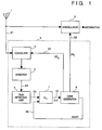
- Fig. 1 is a block diagram showing the first embodiment of the present invention.
- a receiver in this embodiment includes an antenna 1, a synchronization unit 2, and a demodulator 3.
- the demodulation unit 3 de-spreads a spread spectrum signal S1 received by the antenna 1 by using a de-spread signal S2 received through the synchronization unit 2, and extracts information.
- a SAW (surface acoustic wave) convolver 4 performs correlation calculation between the received signal S1 and a local reference signal S3.
- a detector 5 detects the output from the SAW convolver 4.
- a peak detection unit 6 receives an output S4 from the detector 5 and detects a correlation peak signal S5.
- a PLL (phase-locked loop) 7 adjusts the rate of a code generation clock S7 in accordance with the phase difference between the correlation peak signal S5 and a code generation timing signal S6 from a code generator 8. Note that PLL 7 is generally constituted by a phase comparator, a loop filter, and a voltage-controlled oscillator.
- the code generator 8 generates a de-spread code PNi having a code sequence length L and a local reference signal PN0 ⁇ having a code sequence length 2L by using the same clock.
- the signal PN0 ⁇ is a code obtained by inverting the signal PN0 on the time base
- the signal PN0 is a sync code contained in the received signal S1.
- the code generation timing signal S6 indicates, e.g., the start portion of the code sequence of the de-spread signal S2 (PNi), and also indicates the start portion and the 1/2 position of the code sequence of the local reference signal S3.
- Fig. 2 is a timing chart showing the waveforms of signals for a synchronization scheme in the first embodiment in a case wherein code synchronization is established.
- the cross-correlation region of the SAW convolver 4 in this embodiment has a length 2L, as indicated by reference numeral 202, with respect to the code sequence length L of the de-spread signal S2 (PNi) denoted by reference numeral 201.
- the output S4 becomes a signal whose phase is advanced with respect to the code generation timing signal S6 by an amount ⁇ /2. Synchronization establishment and synchronization tracking can therefore be attained by inputting the correlation peak output S5 and the code generation timing signal S6 to the PLL 7.
- the process gain (indicating the degree of resistance to noise) is doubled.
- the distance characteristics are therefore be improved by 2 1/2 times.
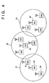
- a radio LAN (local area network) system is to be formed by using spread spectrum communication.
- code synchronization between a BS 34 and a BS 35 and between the BS 35 and a BS 36 can be established by using a sync signal having better distance characteristics than an information signal, thereby preventing interference between different cells.
- Fig. 5 is a block diagram showing the second embodiment of the present invention.
- a code generation timing signal S6B is a signal having a period L/2, which indicates the start portions and the 1/2 positions of a de-spread signal S2 (PNi) and a local reference signal S3B ( PN0 ⁇ ).
- a SAW convolver 4 performs correlation calculation between a received signal S1 and the local reference signal S3B.
- a PLL 7 adjusts the rate of a code generation clock S7 in accordance with the phase difference between a correlation peak signal S5 and the code generation timing signal S6B from a code generator 8.
- Fig. 5 Since the remaining arrangement in Fig. 5 is basically the same as that in the first embodiment (Fig. 1), a description thereof will be omitted.
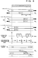
- Fig. 6 is a timing chart showing the waveforms of signals for a synchronization scheme in the second embodiment.
- the cross-correlation region of the SAW convolver 4 in this embodiment has a length L, which is equal to the code sequence length of a spread code (PN0, PNi).
- the correlation peak output S4 has the period L/2 which is equal to that of the code generation timing signal S6B denoted by reference numeral 516. That is, the output S4 becomes a signal whose phase is advanced with respect to the code generation timing signal S6B by an amount ⁇ /2.
- the correlation peak output S4 has the period L/2 which is equal to that of the code generation timing signal S6B denoted by reference numeral 526. That is, the output S4 becomes a signal whose phase is shifted from the code generation timing signal S6B by an amount L/4.
- Fig. 8 shows how synchronization is established by regarding the code generation timing signal indicated by the broken lines as a signal with a phase lead with respect to the correlation peak signal indicated also by the broken lines.
- the phase of the generation timing signal is delayed by the PLL by a given amount, the correlation peak signal as the convolution result is also delayed by 1/2 the given amount. Consequently, as shown in Fig. 8, the phase of the correlation peak signal is locked to a correct code synchronization point. This also applies to the case wherein the code generation timing signal has a phase lag.
- the frequency of a signal input to the PLL is twice that of a signal in the prior art, the time required for phase locking can be shorted to 1/2 that in the prior art without using any high-rate PLL.
- the preamble interval can be shortened by using the synchronization scheme of this embodiment. As a result, the throughput of the communication system can be improved.
- Fig. 10 is a block diagram showing the third embodiment of the present invention.
- a code generator 115 generates a de-spread code PNi having a code sequence length L and a reference code PN0 ⁇ having a code sequence length 2L by using the same clock.
- a code generation timing signal indicates the start portion of the code sequence of the de-spread code PNi, and also indicates the start portion and the 1/2 position of a code sequence PN0 of a reference code.
- a SAW convolver 110 as a correlation detector detects the correlation between a received IF (intermediate frequency) signal processed by a high-frequency unit and the reference spread code PN0 used for de-spread processing.
- the resultant correlation signal is digitized by a peak detector 111, and the digitized signal is then output to a code reset circuit 112 and a phase shift circuit 113.
- the code reset circuit 112 When convolution correlation processing is to be performed by using the SAW convolver 110, the code reset circuit 112 outputs a code reset signal with a code phase obtained by doubling the phase lag of a peak signal with respect to a code generation timing of the reference spread code, thereby establishing code synchronization between the reference code and the de-spread code.
- the phase shift circuit 113 outputs a signal coming from a reference signal generator 114 as a code generator clock without any modification before starting a synchronizing operation. Upon starting reception and obtaining a peak signal, the phase shift circuit 113 shifts the reference clock by an amount obtained by doubling the phase lag of the peak signal with respect to the output clock from the reference signal generator 114, and outputs the shifted clock as a code generator clock, thereby establishing clock synchronization.
- Reference numeral 116 denotes a demodulator for de-spreading the received IF signal by using the de-spread code PNi to extract information.
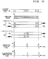
- Fig. 11 is a timing chart showing the waveforms of signals for the synchronization scheme in the third embodiment.
- the cross-correlation region of the convolver 110 in this embodiment has a length 2L, as indicated by reference numeral 122, with respect to a code sequence length L of a de-spread signal S2 denoted by reference numeral 121.
- a correlation peak output S4 can therefore be obtained at the period L, as indicated by reference numeral 125. That is, the output S4 becomes a signal having the same period as that of the code generation timing signal S6 denoted by reference numeral 126. According to this embodiment, since information conversion of a local reference signal need not be performed unlike in the prior art, no correlation peak signal is eliminated when the signals are out of phase, and synchronization can be established regardless of any initial phase differences.
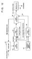
- Fig. 12 is a block diagram showing the fourth embodiment of the present invention.
- a code generator 145 generates a de-spread code PNi having a code sequence length L and a local reference code PN0 ⁇ by using the same clock.
- a code generation timing signal is a signal havinga period L/2, which indicates the start portions and the 1/2 positions of the de-spread signal and the reference signal.
- a code start signal indicates the start portions of the de-spread code and the reference code.
- a SAW convolver 140 as a correlation detector detects the correlation between a received IF signal processed by a high-frequency unit and the reference spread code PN0 ⁇ used for de-spread processing.
- the resultant correlation signal is digitized by a peak detector 141.
- the resultant data is then output to a code reset circuit 142 and a phase shift circuit 143.
- the code reset circuit 142 When convolution correlation processing is to be performed by using the SAW convolver 140, the code reset circuit 142 outputs a code reset signal by delaying the signal based on a code start signal, by a delay amount obtained by doubling the phase lag of a peak signal with respect to the code generation timing of the reference spread code, and resets the reference code and the de-spread code to establish code synchronization.
- the phase shift circuit 143 outputs a signal coming from a reference signal generator 144 as a code generator clock without any modification before a synchronizing operation. Upon starting reception and obtaining a peak signal, the phase shift circuit 143 shifts the reference clock by an amount obtained by doubling the phase lag of the peak signal with respect to the output clock from the reference signal generator 144, and outputs the shifted clock as a code generator clock, thereby establishing clock synchronization.
- Reference numeral 146 denotes a demodulator for de-spreading the received IF signal by using the de-spread code PNi to extract information.
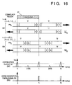
- Fig. 13 is a timing chart showing the waveforms of signals for the synchronization scheme in the fourth embodiment.
- the cross-correlation region of the convolver in this embodiment has a length L which is equal to the code sequence length of a spread code, as indicated by reference numeral 151.
- codes PN0 and PN0 ⁇ coincide with each other within the cross-correlation region of the convolver, as indicated by reference numeral 152.
- the frequency of a signal input to the code reset circuit 142 is twice as high as that of the prior art, the time required for synchronization establishment can be shortened to 1/2 that of the prior art. As shown in Fig. 9, therefore, when transmitting information as a frame, the preamble interval can be shortened by using the synchronization scheme of this embodiment. As a result, the throughput of the communication system can be improved.
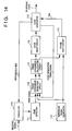
- Fig. 14 is a block diagram showing the fifth embodiment of the present invention.
- a SAW convolver 170 as a correlation detector detects the correlation between a received IF signal processed by a high-frequency unit and a reference spread code used for de-spread processing.
- the resultant correlation signal is digitized by a peak detector 171, and the digitized signal is then output to a phase difference detection circuit 176.
- the phase difference detection circuit 176 detects the phase difference between a peak signal output from the peak detector 171 and the code timing signal and the phase difference between an output clock from a reference frequency generator 174 and a peak signal a plurality of number of times, and outputs the resultant data to a phase-difference calculation circuit 177.
- the above-mentioned number of times is generally set to be about two to five, although it changes depending on a situation.
- the phase difference calculation circuit 177 calculates a phase of the code reset signal and the clock-phase shift amount by using an output from the phase-difference detection circuit 176.
- a plurality of detected phase differences may be averaged, or a most-frequent phase difference of a plurality of detected phase differences may be selected.
- code resetting is performed by using a code phase obtained by doubling the phase difference calculated in this manner, and the clock is shifted by a clock-phase shift amount obtained by doubling the phase difference.
- a code reset circuit 172 receives the code reset signal and establishes code synchronization between the reference code and the de-spread code.
- a phase shift circuit 173 outputs a signal coming from the reference signal generator 174 as a code generator clock without any modification before a synchronizing operation. Upon starting reception and obtaining a peak signal, the phase shift circuit 173 receives the clock-phase shift amount, shifts the peak signal from the reference clock, and outputs the resultant signal as a code generator clock, thereby establishing clock synchronization.
- a peak signal generated by the peak detector 171 has the same period as that of a code generation timing signal of a reference code, as shown in Fig. 11. Even if, therefore, the phase-difference detection circuit 176 detects the peak signal and the code generation timing signal a plurality of number of times, the prolongation of the time required for synchronization seizure can be prevented.
Landscapes
- Engineering & Computer Science (AREA)
- Computer Networks & Wireless Communication (AREA)
- Signal Processing (AREA)
- Synchronisation In Digital Transmission Systems (AREA)
- Cable Transmission Systems, Equalization Of Radio And Reduction Of Echo (AREA)
Applications Claiming Priority (3)
| Application Number | Priority Date | Filing Date | Title |
|---|---|---|---|
| JP33271494 | 1994-12-13 | ||
| JP33271494 | 1994-12-13 | ||
| JP332714/94 | 1994-12-13 |
Publications (3)
| Publication Number | Publication Date |
|---|---|
| EP0717506A2 true EP0717506A2 (fr) | 1996-06-19 |
| EP0717506A3 EP0717506A3 (fr) | 2000-06-28 |
| EP0717506B1 EP0717506B1 (fr) | 2004-09-15 |
Family
ID=18258050
Family Applications (1)
| Application Number | Title | Priority Date | Filing Date |
|---|---|---|---|
| EP95402795A Expired - Lifetime EP0717506B1 (fr) | 1994-12-13 | 1995-12-12 | Appareil de communication à spectre étalé |
Country Status (3)
| Country | Link |
|---|---|
| US (1) | US5812592A (fr) |
| EP (1) | EP0717506B1 (fr) |
| DE (1) | DE69533502T2 (fr) |
Cited By (1)
| Publication number | Priority date | Publication date | Assignee | Title |
|---|---|---|---|---|
| US7054355B2 (en) | 1998-10-06 | 2006-05-30 | Asahi Kasei Kabushiki Kaisha | Spread spectrum signal processing apparatus and spread communication system |
Families Citing this family (5)
| Publication number | Priority date | Publication date | Assignee | Title |
|---|---|---|---|---|
| US6765950B1 (en) * | 1999-04-01 | 2004-07-20 | Custom One Design, Inc. | Method for spread spectrum communication of supplemental information |
| DE60141982D1 (de) * | 2000-09-01 | 2010-06-10 | Broadcom Corp | Satellitenempfänger und entsprechendes verfahren |
| US20080151813A1 (en) * | 2006-12-22 | 2008-06-26 | Adaptix, Inc. | Method and apparatus for fast system initial acquisition in mobile WiMAX systems |
| CN102090012B (zh) * | 2008-05-09 | 2016-06-08 | 诺基亚通信公司 | 基于3g-lte的虚拟导频序列中的多小区信道估计 |
| CN113630150B (zh) * | 2021-08-11 | 2022-05-13 | 电子科技大学 | 一种通信系统高精度时间同步方法 |
Family Cites Families (10)
| Publication number | Priority date | Publication date | Assignee | Title |
|---|---|---|---|---|
| US4567588A (en) * | 1984-03-23 | 1986-01-28 | Sangamo Weston, Inc. | Synchronization system for use in direct sequence spread spectrum signal receiver |
| US5090023A (en) * | 1986-09-29 | 1992-02-18 | Kabushiki Kaisha Kenwood | Spread spectrum communication system |
| JPS6398235A (ja) * | 1986-10-14 | 1988-04-28 | Clarion Co Ltd | スペクトラム拡散受信機 |
| US5260969A (en) * | 1988-11-14 | 1993-11-09 | Canon Kabushiki Kaisha | Spectrum diffusion communication receiving apparatus |
| JP2783578B2 (ja) * | 1989-02-21 | 1998-08-06 | キヤノン株式会社 | スペクトラム拡散通信装置 |
| US4965808A (en) * | 1989-03-01 | 1990-10-23 | Sperry Marine Inc. | Code tracking apparatus with improved resolution for spread spectrum receiver |
| US5315616A (en) * | 1992-12-31 | 1994-05-24 | Gte Government Systems Corporation | Correlator for DSSS communications |
| US5313490A (en) * | 1992-12-31 | 1994-05-17 | Gte Government Systems Corporation | Acquisition apparatus for DSSS communications |
| US5452327A (en) * | 1993-12-28 | 1995-09-19 | Unisys Corporation | Programmable randomly tunable digital demodulator |
| US5495509A (en) * | 1994-03-23 | 1996-02-27 | Loral Corporation | High processing gain acquisition and demodulation apparatus |
-
1995
- 1995-12-08 US US08/569,462 patent/US5812592A/en not_active Expired - Fee Related
- 1995-12-12 EP EP95402795A patent/EP0717506B1/fr not_active Expired - Lifetime
- 1995-12-12 DE DE69533502T patent/DE69533502T2/de not_active Expired - Fee Related
Non-Patent Citations (1)
| Title |
|---|
| None |
Cited By (1)
| Publication number | Priority date | Publication date | Assignee | Title |
|---|---|---|---|---|
| US7054355B2 (en) | 1998-10-06 | 2006-05-30 | Asahi Kasei Kabushiki Kaisha | Spread spectrum signal processing apparatus and spread communication system |
Also Published As
| Publication number | Publication date |
|---|---|
| US5812592A (en) | 1998-09-22 |
| EP0717506B1 (fr) | 2004-09-15 |
| DE69533502D1 (de) | 2004-10-21 |
| DE69533502T2 (de) | 2005-09-15 |
| EP0717506A3 (fr) | 2000-06-28 |
Similar Documents
| Publication | Publication Date | Title |
|---|---|---|
| US6154487A (en) | Spread-spectrum signal receiving method and spread-spectrum signal receiving apparatus | |
| EP1404032B1 (fr) | Récepteur d'accès multiple par division de code à séquence directe et procédé de synchronisation correspondant | |
| US6751247B1 (en) | Method of reducing interference, and radio system | |
| US5260969A (en) | Spectrum diffusion communication receiving apparatus | |
| KR970003966B1 (ko) | 윈도우필터를 이용한 직접확산통신시스템의 수신기 | |
| US6829291B1 (en) | Receiving apparatus and synchronization capturing method | |
| US5815541A (en) | Digital phase locked loop assembly | |
| CA2001349C (fr) | Methode de communication a spectre etale utilisant la modulation csk | |
| EP0717506B1 (fr) | Appareil de communication à spectre étalé | |
| WO2000048346A2 (fr) | Synchronisation non coherente, et non assistee par des donnees du pseudo-bruit et de la porteuse dans un systeme amcr a modulation mdpq ou mdpq | |
| US6072802A (en) | Initial synchronization method in code division multiple access reception system | |
| US6522684B2 (en) | Delay lock loop, receiver, and spectrum spreading communication system | |
| JPH0795731B2 (ja) | データ受信装置の最適クロック形成装置 | |
| US20070177691A1 (en) | Device For Detecting A Frequency Offset | |
| US20060023823A1 (en) | Apparatus for frequency synchronization and method for the same | |
| US7295595B2 (en) | Device for synchronizing a receiver and a transmitter in a communication system | |
| US20020163957A1 (en) | Code division multiple access (CDMA) code timing tracking apparatus | |
| JP2001223674A (ja) | スペクトル拡散復調器 | |
| JPH08237173A (ja) | スペクトラム拡散通信システム | |
| US6775341B2 (en) | Time recovery circuit and method for synchronizing timing of a signal in a receiver to timing of the signal in a transmitter | |
| JP3581067B2 (ja) | Afc機能の有るcdma受信機 | |
| EP0369375B1 (fr) | Dispositif de réception pour communication à étalement de spectre | |
| JPH09116465A (ja) | スペクトル拡散通信用相関器 | |
| JPH07183828A (ja) | スペクトル拡散送信機及び受信機 | |
| JPH07170211A (ja) | 符号同期回路 |
Legal Events
| Date | Code | Title | Description |
|---|---|---|---|
| PUAI | Public reference made under article 153(3) epc to a published international application that has entered the european phase |
Free format text: ORIGINAL CODE: 0009012 |
|
| AK | Designated contracting states |
Kind code of ref document: A2 Designated state(s): DE FR GB |
|
| PUAL | Search report despatched |
Free format text: ORIGINAL CODE: 0009013 |
|
| AK | Designated contracting states |
Kind code of ref document: A3 Designated state(s): DE FR GB |
|
| 17P | Request for examination filed |
Effective date: 20001115 |
|
| 17Q | First examination report despatched |
Effective date: 20030611 |
|
| GRAP | Despatch of communication of intention to grant a patent |
Free format text: ORIGINAL CODE: EPIDOSNIGR1 |
|
| GRAS | Grant fee paid |
Free format text: ORIGINAL CODE: EPIDOSNIGR3 |
|
| GRAA | (expected) grant |
Free format text: ORIGINAL CODE: 0009210 |
|
| AK | Designated contracting states |
Kind code of ref document: B1 Designated state(s): DE FR GB |
|
| PG25 | Lapsed in a contracting state [announced via postgrant information from national office to epo] |
Ref country code: FR Free format text: LAPSE BECAUSE OF FAILURE TO SUBMIT A TRANSLATION OF THE DESCRIPTION OR TO PAY THE FEE WITHIN THE PRESCRIBED TIME-LIMIT Effective date: 20040915 |
|
| REG | Reference to a national code |
Ref country code: GB Ref legal event code: FG4D |
|
| REF | Corresponds to: |
Ref document number: 69533502 Country of ref document: DE Date of ref document: 20041021 Kind code of ref document: P |
|
| PG25 | Lapsed in a contracting state [announced via postgrant information from national office to epo] |
Ref country code: GB Free format text: LAPSE BECAUSE OF NON-PAYMENT OF DUE FEES Effective date: 20041215 |
|
| PLBE | No opposition filed within time limit |
Free format text: ORIGINAL CODE: 0009261 |
|
| STAA | Information on the status of an ep patent application or granted ep patent |
Free format text: STATUS: NO OPPOSITION FILED WITHIN TIME LIMIT |
|
| GBPC | Gb: european patent ceased through non-payment of renewal fee |
Effective date: 20041215 |
|
| 26N | No opposition filed |
Effective date: 20050616 |
|
| EN | Fr: translation not filed | ||
| PGFP | Annual fee paid to national office [announced via postgrant information from national office to epo] |
Ref country code: DE Payment date: 20051207 Year of fee payment: 11 |
|
| PG25 | Lapsed in a contracting state [announced via postgrant information from national office to epo] |
Ref country code: DE Free format text: LAPSE BECAUSE OF NON-PAYMENT OF DUE FEES Effective date: 20070703 |