EP0717857B1 - Faseroptisches verteilersystem - Google Patents
Faseroptisches verteilersystem Download PDFInfo
- Publication number
- EP0717857B1 EP0717857B1 EP94925581A EP94925581A EP0717857B1 EP 0717857 B1 EP0717857 B1 EP 0717857B1 EP 94925581 A EP94925581 A EP 94925581A EP 94925581 A EP94925581 A EP 94925581A EP 0717857 B1 EP0717857 B1 EP 0717857B1
- Authority
- EP
- European Patent Office
- Prior art keywords
- fibre
- fibres
- tray
- splice
- splitter
- Prior art date
- Legal status (The legal status is an assumption and is not a legal conclusion. Google has not performed a legal analysis and makes no representation as to the accuracy of the status listed.)
- Expired - Lifetime
Links
Images



Classifications
-
- G—PHYSICS
- G02—OPTICS
- G02B—OPTICAL ELEMENTS, SYSTEMS OR APPARATUS
- G02B6/00—Light guides; Structural details of arrangements comprising light guides and other optical elements, e.g. couplings
- G02B6/46—Processes or apparatus adapted for installing or repairing optical fibres or optical cables
-
- G—PHYSICS
- G02—OPTICS
- G02B—OPTICAL ELEMENTS, SYSTEMS OR APPARATUS
- G02B6/00—Light guides; Structural details of arrangements comprising light guides and other optical elements, e.g. couplings
- G02B6/44—Mechanical structures for providing tensile strength and external protection for fibres, e.g. optical transmission cables
- G02B6/4439—Auxiliary devices
- G02B6/444—Systems or boxes with surplus lengths
- G02B6/4441—Boxes
- G02B6/4442—Cap coupling boxes
-
- G—PHYSICS
- G02—OPTICS
- G02B—OPTICAL ELEMENTS, SYSTEMS OR APPARATUS
- G02B6/00—Light guides; Structural details of arrangements comprising light guides and other optical elements, e.g. couplings
- G02B6/44—Mechanical structures for providing tensile strength and external protection for fibres, e.g. optical transmission cables
- G02B6/4439—Auxiliary devices
- G02B6/444—Systems or boxes with surplus lengths
- G02B6/4452—Distribution frames
-
- G—PHYSICS
- G02—OPTICS
- G02B—OPTICAL ELEMENTS, SYSTEMS OR APPARATUS
- G02B6/00—Light guides; Structural details of arrangements comprising light guides and other optical elements, e.g. couplings
- G02B6/44—Mechanical structures for providing tensile strength and external protection for fibres, e.g. optical transmission cables
- G02B6/4439—Auxiliary devices
- G02B6/444—Systems or boxes with surplus lengths
- G02B6/4452—Distribution frames
- G02B6/44524—Distribution frames with frame parts or auxiliary devices mounted on the frame and collectively not covering a whole width of the frame or rack
-
- G—PHYSICS
- G02—OPTICS
- G02B—OPTICAL ELEMENTS, SYSTEMS OR APPARATUS
- G02B6/00—Light guides; Structural details of arrangements comprising light guides and other optical elements, e.g. couplings
- G02B6/44—Mechanical structures for providing tensile strength and external protection for fibres, e.g. optical transmission cables
- G02B6/4439—Auxiliary devices
- G02B6/444—Systems or boxes with surplus lengths
- G02B6/44528—Patch-cords; Connector arrangements in the system or in the box
-
- G—PHYSICS
- G02—OPTICS
- G02B—OPTICAL ELEMENTS, SYSTEMS OR APPARATUS
- G02B6/00—Light guides; Structural details of arrangements comprising light guides and other optical elements, e.g. couplings
- G02B6/44—Mechanical structures for providing tensile strength and external protection for fibres, e.g. optical transmission cables
- G02B6/4439—Auxiliary devices
- G02B6/444—Systems or boxes with surplus lengths
- G02B6/4453—Cassettes
- G02B6/4455—Cassettes characterised by the way of extraction or insertion of the cassette in the distribution frame, e.g. pivoting, sliding, rotating or gliding
-
- G—PHYSICS
- G02—OPTICS
- G02B—OPTICAL ELEMENTS, SYSTEMS OR APPARATUS
- G02B6/00—Light guides; Structural details of arrangements comprising light guides and other optical elements, e.g. couplings
- G02B6/44—Mechanical structures for providing tensile strength and external protection for fibres, e.g. optical transmission cables
- G02B6/4439—Auxiliary devices
- G02B6/4471—Terminating devices ; Cable clamps
-
- G—PHYSICS
- G02—OPTICS
- G02B—OPTICAL ELEMENTS, SYSTEMS OR APPARATUS
- G02B6/00—Light guides; Structural details of arrangements comprising light guides and other optical elements, e.g. couplings
- G02B6/46—Processes or apparatus adapted for installing or repairing optical fibres or optical cables
- G02B6/50—Underground or underwater installation; Installation through tubing, conduits or ducts
- G02B6/501—Underground or underwater installation; Installation through tubing, conduits or ducts underground installation of connection boxes
Definitions
- This invention relates to an optical fibre management system, and in particular to an optical fibre splitter array sub-assembly for incorporation in the node of an optical fibre telecommunications network.
- the telecommunications network includes a trunk network which is substantially completely constituted by optical fibre, and a local access network which is substantially completely constituted by copper pairs. Flexibility in the copper access network is provided at two points en route to the customer; firstly, at street-side cabinets serving up to 600 lines; and secondly, at distribution points serving around 10-15 lines. In total, the network has about 250, 000km of underground ducts, 83, 000 cabinets, 3.1 million distribution points and 3.7 million manholes and joint boxes. Eventually, it is expected that the entire network, including the access network, will be constituted by fibre.
- the ultimate goal is a fixed, resilient, transparent telecommunications infrastructure for the optical access network, with capacity for all foreseeable service requirements.
- One way of achieving this would be to create a fully-managed fibre network in the form of a thin, widespread overlay for the whole access topography as this would exploit the existing valuable access network infrastructure.
- Such a network could be equipped as needs arise, and thereby could result in capital expenditure savings, since the major part of the investment will be the provision of terminal equipment on a 'just in time' basis. It should also enable the rapid provision of extra lines to new or existing customers, and flexible provision or reconfiguration of telephony services.
- the network should be single mode optical fibre, with no bandwidth limiting active electronics within the infrastructure. Consequently, only passive optical networks (PONs) which can offer this total transparency and complete freedom for upgrade, should be considered.
- PONs passive optical networks
- the most common passive optical network is the simplex single star, with point-to-point fibre for each transmit and receive path, from the exchange head end (HE) to the customer network terminating equipment (NTE).
- This network design has been used throughout the world and meets all the access criteria. It involves high fibre count cables, and unique electro-optic provision at HE and NTE for each customer. The resulting inherent cost can only be justified for large business users, who generally also require the security of diverse routing, which increases the cost still further.
- BT demonstrated splitter technology in a system for telephony on a passive optical network (TPON), with a 128 way split and using time division multiplex (TDM) running at 20Mb/s.
- TDM time division multiplex
- ISDN basic rate integrated service digital network
- splitter based PON architecture will reduce the cost of fibre deployment in the access network.
- savings will result from:
- PON architecture can be tailored to suit the existing infrastructure resources (duct and other civil works).
- Total network transparency will retain the option for future services to be provided on different wavelengths to the telecommunications, which for TPON is in the 1300nm window.
- other services such as broadband access for cable television and high definition television, or business services, such as high bit rate data, video telephony or video conferencing, can be provided.
- the huge bandwidth potential of fibre promises virtually unlimited capacity for the transparent network.
- WDMs wavelength division multiplexers
- the architecture adopted for the PON topography will be influenced by transmission techniques, and the availability of suitable splitter components. Transmission options are simplex (two fibre paths), duplex, half duplex or diplex (single fibre path).
- Simplex working increases the complexity of the infrastructure due to the two fibres per circuit required. However, it benefits from the lowest optical insertion loss, due to the absence of duplexing couplers; and the lowest return loss, since such systems are insensitive to reflections of less than 25 dBm with separate transmit and receive paths. Duplex and half duplex working each have an insertion loss penalty of 7dB from the duplexing couplers, and diplex working replaces these with WDMs, with a reduced penalty of 2dB.
- the present invention provides an optical fibre management system comprising a plurality of splice arranged in a stack, each splice tray having a main body portion for holding at least one splice and for storing fibres leading to the or each splice, and a fibre entry/exit portion for feeding fibre to/from the main body portion, wherein each tray is mounted in the stack so as to be movable from a stacked position, in which it is aligned with the other trays, to first and second operating positions, wherein only the fibre entry/exit portion is accessible in the first operating position, and the main body portion and the fibre entry/exit portion are accessible in the second operating position, the system being characterised in that each of the splice trays (4) is provided with a mounting arm, one end of which is fixed to the main body portion of the tray, the other end of which carries a retaining ring, with a hinged joint located intermediate the two ends of the mounting arm, and wherein the system further comprises a retaining rod which passes through the
- the mounting arm of each of the splice trays is such that the two parts of the arm on opposite sides of the hinge lie in close proximity to one another in a folded-back position against the main body portion of that tray when the tray is its stacked position, said two arm portions being in a generally straight line configuration when that tray is in its first operating position.
- each splice tray is formed with at least one clip-on test aperture, each clip-on test aperture being constituted by an aperture formed in the associated fibre entry/exit portion, the arrangement being such that, in use, with a given splice tray in its first operating position, any fibre which overlies an aperture can be accessed by a test probe via said aperture.
- each splice tray may be provided with at least two fibre entry/exit ports.
- the system further comprises at least one fibre routing mechanism for routing fibre to the fibre entry/exit portion of each splice tray, each fibre routing mechanism being operative such that fibre routed thereby is constrained from being bent to a radius that is less than the minimum bend radius for live optical fibre and said fibre routing mechanism being further operative such that fibre routed thereby is constrained from being bent to a radius that is less than the minimum bend radius for live optical fibre whenever the associated splice tray is moved from its stacked position to either its first operating position or its second operating position.
- each fibre routing mechanism being operative such that fibre routed thereby is constrained from being bent to a radius that is less than the minimum bend radius for live optical fibre.
- the system further comprises a fibre break-out tray, said fibre breakout tray comprising; means for storing unbroken multi-fibre cable elements such that said stored cable elements are not bent to a radius that is less than the minimum bend radius for cable elements which contain live optical fibre; means for storing unused fibre end portions that have been removed from cable elements such that stored unused fibre end portions are not bent to a radius that is less than the minimum bend radius for live optical fibre; and means for routing fibre end portions from one of the cable elements to one of a plurality of further fibre routing means, such that the fibre end portions routed thereby are not bent to a radius that is less than the minimum bend radius for live optical fibre.
- At least one fibre routing mechanism is provided for guiding the fibre end portions from the break-out tray towards the stack of splice trays.
- first and second fibre routing mechanisms pass from the break-out tray to first and second of the splice trays, the first fibre routing mechanism carrying, in use, first fibre end portions from two cut fibres, and the second fibre routing mechanism carrying, in use, second fibre end portions from said two cut fibres.
- the system may further comprise first and second splitter mats, each splitter mat housing first and second input fibres spliced to a plurality of output fibres by splitter means.
- said first input fibres are constituted by fibres which, in use, are spliced to said first fibre end portions in the first splice tray
- said second input fibres are constituted by fibres which, in use, are spliced to said second fibre end portions in the second splice tray.
- each output fibre of the first splitter mat is paired with a respective output fibre of the second splitter mat, the fibres of each pair being spliced, in use, to customer fibres in a respective one of the other splice trays in the stack.
- the fibres may be guided, in pairs, between the splitter mats and the associated splice trays in respective fibre routing mechanisms.
- each splitter mat includes a pair of channels for housing its input fibres, respective output channels for housing its output fibres, and holder means for housing its splitter means.
- the input channels and the output channels of each splitter mat terminate at one edge of that splitter mat, each splitter mat being formed with a curved guide for guiding its output fibres from its splitter means to its output channels in such a manner that said output fibres are not bent to a radius that is less than the minimum bend radius for live optical fibre.
- Each of the splitter mats may be made of a flexible polymer, and the splitter mats may be positioned together against an edge of the stack of splice trays. Conveniently, the splitter mats are held in position against an edge of the stack of splice trays by a backing plate.
- the backing plate is provided with a plurality of outwardly-projecting ribs, each of which is formed with a plurality of apertures which constitute a matrix of tie points for the attachment of cable ties which, in use, support the fibre routing mechanisms.
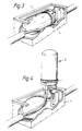
- Figures 1 and 2 show a node N forming part of a ring topography PON.
- the node N includes a stack of three splitter array sub-assemblies S 1 , S 2 and S 3 and a break-out tray T.
- a 96 fibre cable C which forms a ring (loop) centred on a local exchange (not shown), enters the break-out tray T via a cable entry portion 2 (see Figure 12) after passing through a node base 1.
- the cable passes at least twice round a generally oval perimeter track 3 of the tray T, and leaves the tray via the portion 2.
- the 96 fibres are housed in twelve flexible tubes (not shown) made of plastics material, each of the tubes containing eight primary-coated fibres.
- the tray T includes a break-out region B in which individual fibre end portions, formed by cutting into one of the tubes, are led to the splitter array sub-assemblies S 1 , S 2 and S 3 .
- the tray T stores a sufficient length of the cable C so that, after cutting one of the tubes in the middle of this stored length, and stripping back that tube to expose its optical fibres, each of the originally continuous fibres forms two fibre end portions whose length is sufficient to be led to the splitter array sub-assemblies S 1 , S 2 and S 3 , and to leave spare fibre which can be stored for future use.
- Figures 3 and 4 show the mounting of the node N in a footway box F, a dome-shaped cover D being fixed to the node base 1 prior to mounting.
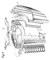
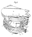
- the sub-assembly S 1 includes a stack of ten splice trays 4, each of which is 8mm thick.
- the trays 4 are supported (in a manner described below) by a stainless steel chassis 5 constituted by a top plate 5a, a base plate 5b and a back plate 5c.
- Each of the splice trays 4 is a single circuit splice tray, that is to say, in use, it has two incoming optical fibres (one eacn for transmitting and receiving), and two outgoing optical fibres (one each for transmitting and receiving).
- the three plates 5a, 5b and 5c are welded together, and the top plate 5a of the sub-assembly S 1 can be fixed to the base plate 5b of the adjacent sub-assembly S 2 (not shown in Figures 5 and 6) by means of mounting bolts (not shown). Similar mounting bolts can be used to fix the plate 5a of the sub-assembly S 1 and the plate 5b of the sub-assembly S 3 to support means (not shown) in the node N.
- the chassis 5 also supports an input splitter array mat 6, an output splitter array mat 7, and a splitter array back cover 8.
- the input mat 6 carries (as is described below with reference to Figure 10) fibres which carry telecommunications signals from the exchange to customers. These fibres are termed transmit fibres.
- the output mat 7 carries fibres which carry telecommunications signals from customers to the exchange. These fibres are termed receive fibres.
- the mats 6 and 7 are made of a flexible polymer, for example an elastomeric polymer such as injection mouldable zantoprene, or polyurethane.
- the back cover 8 is made of flexible polypropylene (which is also injection mouldable). This inherent flexibility ensures that, in use, the mats 6 and 7 are held firmly against the chassis back plate 5c by the back cover 8.
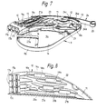
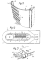
- each splice tray 4 has a main body portion 9 and a fibre entry portion 10 which also constitutes a clip-on test area. Fibre access to the main body portion 9 from the fibre entry portion 10 is via a channel 11.
- the main body portion 9 is of oval configuration, having an oval base 9a and an upstanding peripheral wall 9b.
- a hollow mandrel 12 is provided on the base 9a adjacent to the entry channel 11.
- the mandrel 12 is of rounded square cross-section, is sized to ensure minimum bend requirements for live fibre passing around it, and has a fibre inlet aperture 12a through which dark fibre can pass for internal storage.
- a channel 13 is defined between the mandrel 12 and the peripheral wall 9b, the channel 13 leading to a further channel 14 which leads around the inside of the wall to a splice holder region 15.
- this region 15 houses a splice holder (not shown) for splicing two incoming fibres to two outgoing fibres.
- a direction reversing channel 16 leads from the channel 14 adjacent to the region 15 back to that portion of the channel 14 which adjoins the channel 13 adjacent to the mandrel 12.
- each splice tray 4 inciudes three fibre entry/exit ports 17a, 17b and 17c (see Figure 8). Diverging channels 18a and 18b are provided to lead fibre between the port 17a and the channel 11 via respective apertures 19a and 19b. These apertures 19a and 19b constitute what are known as “clip-on apertures", and provide easy access to the associated fibres in order to measure the light passing there along, and hence to determine the quality of the splices. These clip-on apertures, and associated light measurement apparatus, are described in the specification of our International patent application WO 93/00600.
- Similar diverging channels 20a and 20b are provided to lead fibre between the port 17c and the channel 11 via respective clip-on apertures 21a and 21b.
- a single channel 22 is provided for leading fibre between the port 17b and the channel 11.
- the channel 22 is not provided with a clip-on aperture.
- Each splice tray 4 is also provided with a number of fibre retention tabs 23 for holding fibre in the various channels 11, 13, 14, 16, 18a, 18b, 20a, 20b and 22.
- One of these tabs (indicated by the reference numeral 23a) is generally V-shaped, and extends from the curved end of the peripheral wall 9b remote from the mandrel 12 about halfway across, and above, that portion of the base 9a between that wall portion and the mandrel.
- Each tray 4 is pivotally mounted on the splitter array back cover 8 by means of a leash 24 and a retaining ring 25 which are moulded integrally with the rest of the tray.
- the leash 24 of each tray 4 has two arms 24a and 24b joined together by a hinge 24c.
- Its retaining ring 25 is a friction fit within a groove 26 formed in the back cover 8 (see Figure 11).
- a rod passes through all the retaining rings 25 and through apertures (not shown) in the top and base plates 5a and 5b.
- Each of the splitter array sub-assemblies S 1 , S 2 and S 3 is associated with two fibres (four fibre end portions) of the eight fibres in the cut tube of the cable.
- the remaining two fibres (four fibre end portions) from the cut tube are stored in the break-out tray T as is described below with reference to Figure 13.
- the cable C is in the form of a ring, telecommunications signals can travel to/from the exchange in either direction round the ring.
- the main direction For convenience, one of the directions is termed the main direction, and the other the standby direction. In practice, only main fibres will be used for normal signalling, the standby fibres only being used in the eventuality of main fibre failure.
- the two main fibre end portions associated with say the splitter array sub-assembly S 1 pass from the break-out tray T to the lowest splice tray 4 of that assembly, the fibre end portions being supported in, and protected by, a bend limiting tube 27a (see Figure 6).
- This bend limiting tube 27a is a proprietary item made of polypropylene ringed tubing which, though flexible, cannot easily be bent beyond minimum bend radius requirements for live fibre.
- the bend limiting tube 27a terminates in the port 17a of the lowest splice tray 4, and its two fibre end portions are led into the main body portion 9 via the channels 18a and 18b, the clip-on apertures 19a and 19b, and the channel 11.
- fibre end portions are then spliced to the ends of a pair of fibres which (as is described below) are associated with the mats 6 and 7.
- the two splices are then positioned in a splice holder which is then mounted in the region 15.
- the four fibres leading to the splices are then stored in the main body portion 9 of the tray 4 with two of the fibres (for example those from the break-out tray T) being led away from the splices in the channel 14, and the other two fibres being led away from the splices via the channel 13 and the reversing channel 16.
- a length of each of the fibres is stored in the main body portion 9 of the tray 4 by passing these fibres one or more times round the mandrel 12 and under the V-shaped tab 23a.
- the fibres' natural resilience will ensure that the loops of fibre expand outwardly into a configuration of varying diameter turns.
- the provision of stored fibre permits a minimum of ten re-splices of each of the splices to be carried out during the lifetime of the assembly.
- the two fibres which are associated with the mats 6 and 7 leave the main body portion of the tray 4 via the channel 11. They are then led to the port 17c of the entry portion 10 via the clip-on windows 21a and 21b and the channels 20a and 20b. These fibres are then led to the mats 6 and 7 within a bend limiting tube 27c (see Figure 6).
- One of these main input fibres terminates on the input mat 6, where (as is described below with reference to Figure 10) it is joined by s-plitter means to eight output fibres.
- the other of these main input fibres terminates on the output mat 7, where it is joined by splitter means to eight output fibres.
- the two standby fibre end portions associated with this splitter array sub-assembly S 1 pass from the break out tray T to the second lowest splice tray 4 of that assembly.
- these two fibre end portions are spliced to two fibres which are led back to the mats 6 and 7 and so are termed standby input fibres, and each of the standby input fibres is joined by splitter means to the same eight output fibres as the corresponding main input fibre.
- the fibre arrangement on this second lowest splice tray 4 is the same as that for the lowest splice tray. Similarly, fibres enter and leave this splice tray 4 in bend limiting tubes 27a and 27c.
- the remaining eight splice trays 4 in the sub-assembly S 1 of Figures 5 and 6 are customer splice trays. As the fibre arrangement in each of these customer splice trays 4 is the same, this will be described in detail for only one of these trays.
- one of the output fibres from each of the mats 6 and 7 (that is to say a transmit fibre and a receive fibre) is led to the port 17c of a given customer splice tray 4 inside a bend limiting tube 27c.
- These two fibres are led into the main body portion 9 of the tray 4 via the channels 20a and 20b, the clip-on windows 21a and 21b, and the channel 11.
- these fibres are spliced to two fibres of a four-fibre blown fibre unit associated with a given customer.
- a unit has four fibres in a single tube, the tube being fed between the customer and the node N by the well known fibre blowing technique (see EP 108590).
- the customer's blown fibre unit is led to the port 17a of the splice tray 4 within a bend limiting tube 27a.
- the blown fibre coatings are stripped away from the four fibres "downstream" of the port 17a.
- Two of the fibres within the unit are fed to the main body portion 9 of the splice tray 4 via the channels 18a and 18b, the clip-on apertures 19a and 19b, and the channel 11.
- the two other fibres (which are spare fibres not for immediate use) are fed to the main body portion 9 of the splice tray 4 via the channels 22 and 11. All four fibres then pass round the mandrel 12 within the channel 13, and then back to the mandrel after passing along the channels 14 and 16.
- the two spare (dark) customer fibres pass through the aperture 12a and are stored inside the mandrel 12.
- each of the spliced fibres has a length to be stored (enabling up to ten re-splices to be made during the lifetime of the assembly), these fibre lengths likewise being stored by looping them each one or more times round the mandrel 12 and under the V-shaped tab 23a.
- the tray 4 In order to access the splices within a given splice tray 4, it is necessary to remove the rod holding the retaining rings 25 in position, prior to the pulling that tray out of the stack sufficiently far to gain access to the splices. In this position (the second operating position), the tray 4 is maintained in position by its bend limiting tubes.
- the two spare customer fibres stored within the mandrel 12 of a given splice tray 4 can be used to replace the two live fibres of that customer in the event of these fibres failing. More importantly, however, they can be used to provide that customer with additional lines or service.
- each fibre pair can provide up to 32 lines using customer premises equipment (CPE) electronics such as an optical network unit (ONU) matched to an optical line terminal (OLT) at the exchange.
- CPE customer premises equipment
- ONU optical network unit
- OLT optical line terminal
- Each pair of fibres can also provide a Megastream service.
- the two spare fibres are removed from their storage position within the mandrel 12, and are led to the fibre entry portion 10 of the tray 4 via the channels 13 and 11.
- This tube 27b is routed via the back cover plate 8 to another splice tray 4 - usually a splice tray of another of the sub-assemblies S 2 or S 3 of the node N.
- the tube 27b terminates at the port 17a of this tray 4, and the two fibres are led into the main body portion 9 via the channels 18a and 18b, the apertures 19a and 19b, and the channel 11.
- the "exchange" fibres could be either a second pair of fibres from the break-out tray T (direct exchange fibres), or a pair of output fibres from the mats 6 and 7 (indirect exchange fibres).
- the bend limiting tubes 27a, 27b and 27c of each of the splice trays 4 are provided with respective support manifolds M (see Figures 6 and 9).
- Each manifold M is a sliding friction fit on a flanged portion (not shown) of the chassis back plate 5c, and is provided with an open aperture 28a for supporting the associated bend limiting tube 27a, and with a pair of closed apertures 28b and 28c for supporting respectively the associated bend limiting tube 27b (if there is one) and the associated bend limiting tube 27c.
- the manifolds M are made of injection moulded filled nylon.
- FIG 10 shows the input mat 6 of the sub-assembly S 1 .
- the output mat 7 of this sub-assembly being of identical construction to the input mat 6, will not be described in detail.
- the mat 6 includes an input slot 29 for receiving the main input fibre, and an input slot 30 for receiving the standby input fibre. These two slots 29 and 30 lead to an aperture 31 which houses a 2x2 fused coupler (not shown).
- the two output fibres from this fused coupler are led via a curved channel 32 around a mandrel 33.
- the mandrel 33 has a radius of 30mm, and so fulfils the minimum bend requirements for live fibre.
- Each of the fused coupler output fibres is spliced to an input fibre to a respective 1x4 planar coupler (splitter). The two splices are stored in a recess 35b.
- the two planar couplers (not shown) are housed in an aperture 34 adjacent to the aperture 31.
- the two fibres pass from the mandrel 33 to their planar couplers via the curved end wall 35a of a recessed portion 35 of the mat 6, and via respective curved slot 36.
- the eight output fibres of the two planar couplers pass round the mandrel 33 via a slot 37. These fibres then leave the mat 5 via respective output slots 38 which fan out over the recessed portion 35 and the adjacent raised portion which defines the curved end wall 35a.
- the mat 6 thus forms a 2x8 splitter for the transmit fibres, with one of its inputs being the main transmit input fibre and the other the standby transmit input fibre. As mentioned above, only main fibres are used in normal operation, so the mat 6 acts as a 1x8 splitter. However, should there be problems with the main fibre route, the mat 6 will still act as a 1x8 splitter with the standby receive fibre as its input fibre.
- the mat 7 constitutes a 2x8 splitter for the receive fibres.
- FIG 11 shows the splitter array back cover 8 of the sub-assembly S 1 in greater detail.
- the back cover 8 is formed with a pair of longitudinally-extending grooves 8a adjacent to that end remote from the groove 26. These grooves 8a reduce the thickness of the back cover in this end region, and so enhance the flexibility of the back cover, thereby ensuring that, in use, the back cover holds the mats 6 and 7 firmly against the chassis back plate 5c.
- this end region of the back cover 8 is formed with an in-turned L - shaped flange 8b which can be snapped over grooves 28d formed in the manifolds M to hold the back cover to the chassis 5 with the mats 6 and 7 firmly sandwiched therebetween.
- the outer surface of the back cover 8 is also provided with a plurality of longitudinally-extending ribs 8c, the base of each rib being formed with a plurality of apertures 8d. These apertures 8d extend right through the back cover 8 to its inside surface, and constitute a matrix of tie points for the attachment of cable ties which are used to tie the bend limiting tubes 27a, 27b and 27c to the sub-assembly S.
- Figure 12 shows the break-out tray T in greater detail.
- two loops of the cable are stored in the track 3, before the cable exits the break-out tray T via the entry portion 2, and one of the tubes of the cable is cut in the middle of its stored length.
- One of the cut fibres forms the main fibre for the splitter array sub-assembly shown in Figures 5 and 6, and another the standby fibre for that sub-assembly.
- the remaining fibres can be main and standby fibres for other splitter array sub-assemblies S 2 and S 3 of the node N, or can be stored around a mandrel 39 at that end of the tray T remote from the cable entry portion 2.
- the mandrel 39 has a rounded rectangular cross-section, and is sized so that fibre coiled therearound does not exceed minimum bend radius requirements.
- the break-out region B of the tray T is formed with a plurality of curved upstanding fingers 40, adjacent pairs of which define sixteen fibre feed channels 41.
- the two fibre end portions that constitute the main fibres associated with the lowest splice tray 4 of the sub-assembly S 1 are fed through the first channel 41 (that is to say through the channel nearest the entry portion 2).
- the two fibre end portions that constitute the standby fibres associated with the second lowest splice tray 4 are fed through the second channel 41.
- the break-out tray T can handle sixteen pairs of fibre end portions, that is to say all the fibre end portions from two cut tubes.
- the two fibres then pass into the bend limiting tube 27a associated with the lowest splice tray 4 of the sub-assembly S 1 .
- This tube 27a passes through an aperture 42 in a raised portion 43 of the break-out region B (see Figure 13), and is tied in place by ties (not shown) associated with a further aperture 44.
- a preferred form of TPON includes a 32-way split, that is to say each fibre from the exchange serves 32 actual customers via one or more splitting (flexibility) points such as the node N described above.
- the node N defines an Sway split, it could be used as a primary splitting point, in which case each of the "customer" fibres leaving the node would lead to a respective secondary splitting point.
- Each of the secondary splitting points would be similar to the node N, but each incoming fibre would be split four ways rather than eight ways.
- the terms "customer splice trays” and “customer fibres” used above should be taken to mean splice trays and fibres associated with either actual customers or with downstream splitting points.
- the nodes N could also be secondary nodes.
- the primary node would be similar to the node N, but each incoming (exchange) fibre would be split four ways rather than eight ways.
- splitter array sub-assembly is extremely flexible in that it can readily be adapted to suit different requirements.
- it is adaptable to any splitting ratio by varying the number of splice trays used and the size and form of the splitter array mats 6 and 7.
- splitting from a plurality of exchange fibres can be accomplished at any given point, using different splitting ratios in each sub-assembly if required.
- the fitter When the sub-assembly is to commissioned, the fitter needs only to cut one or more tubes of the cable C, feed main and standby fibre end portions to the lowest two splice trays 4 of the sub-assembly, store spare cut fibre end portions in the break-out tray T, splice the main and standby fibre end portions to the main and standby input fibres already present in the two splice trays, and to splice "customer" fibres to the fibres already present in the other splice trays 4. In this way, the amount of skilled work which has to be carried out on site is reduced to a minimum. In particular, the fitter does not need to carry out any intricate splicing for splitting purposes.
- the bend limiting tubes ensure that the fibres guided therein are never bent beyond the minimum bend requirements for live fibre even when the splice trays are pivoted out of the stack to either of their operating positions. This guarantees the transmission performance of live fibres carried by the bend limiting tubes.
- the sub-assembly described above could also be adapted for use in a spur joint. In such a case, no splitting is required, so the sub-assembly would not include the mats 6 and 7.
- a first type of spur joint all twelve tubes of the fibre cable C would be cut, thereby forming twelve main fibre tube ends and twelve standby fibre tube ends.
- the fibres of six of the main fibre tube ends would then be spliced to the fibres of six of the standby fibre tube ends in special (single element) splice trays 45 (as is described below with reference to Figure 14).
- the fibres of the remaining six main fibre tube ends are then spliced to "customer" fibres in 24 splice trays 4.
- the fibres of the remaining six standby fibre tube ends are spliced to 48 "customer" fibres in 24 splice trays 4.
- two fibres are fed, in bend limiting tubes, from a breakout tray (not shown) to each of the 48 splice trays 4, where they are spliced to "customer" fibres in a similar manner to that described above with reference to Figures 5 and 6.
- a respective main fibre tube end and a respective standby fibre tube end are fed from the break-out tray to each of the splice trays 45 (see Figure 14), each tube end being in a respective bend limiting tube (not shown, but similar to the bend limiting tubes 27a, 27b and 27c).
- Each tray 45 has a main body portion 46 and a tube entry portion 47.
- the main body portion 46 is of oval configuration, having an oval base 46a and an upstanding peripheral wall 46b. Fibre access to the main body portion 46 from the tube entry portion 47 is via a channel 48.
- Channels 49, 50, 51 and 52 are provided in the main body portion 46 to guide both main and standby fibres to a pair of splice holder regions 53.
- the channel 51 is a direction reversing channel, and permits main and standby fibres to approach each of the splice holder regions 53 from opposite directions.
- Each splice tray 45 is also provided with a number of fibre retention tabs 54 for holding fibre in the various channels 49 to 52.
- each splice tray 45 includes two tube entry/exit ports 55a and 55b.
- Channels 56a and 56b are provided to lead fibre between the ports 55a and 55b and the channel 48.
- the splice tray is provided with a leash 57 and a retaining ring 58 (similar to the leash 24 and the retaining ring 25 of the tray 4).
- the leash 57 permits the tray 45 to be pivoted out of a stack of trays to enable access to the tube entry portion 47.
- a main fibre tube end is led to the port 55a of each of the splice trays 45, and a standby fibre tube end is led to the port 55b of each of the splice trays 45.
- the tubes are cut away to expose the fibres.
- the fibres are then fed into the main body portions 46 of the trays, where they are spliced.
- the eight splices in each tray 45 are then positioned, four in each of a pair of splice holders, and the splice holders are then mounted in the regions 53.
- the fibres leading to the splices are then stored in the main body portions 46 of the trays 45.
- a length of each of the fibres is stored in the main body portion 46 of the associated tray 45 by passing these fibres one or more times round an upstanding mandrel 59 and under the tabs 54.
- the fibres natural resilience will ensure that the loops of fibre expand outwardly to a configuration of varying diameter turns.
- the provision of stored fibre permits re-splicing to be carried out during the lifetime of the assembly.
- the number of fibres forming the spur can be varied.
- the spur could be formed from the fibres of one cut tube.
- the spur would contain 16 fibres (eight main fibres and eight standby fibres from a single cut tube) and 88 fibres (from the remaining eleven tubes - either cut and spliced or uncut and coiled) would continue through on the ring.
Landscapes
- Physics & Mathematics (AREA)
- General Physics & Mathematics (AREA)
- Optics & Photonics (AREA)
- Light Guides In General And Applications Therefor (AREA)
- Management, Administration, Business Operations System, And Electronic Commerce (AREA)
- Mechanical Coupling Of Light Guides (AREA)
- Geophysics And Detection Of Objects (AREA)
- Optical Communication System (AREA)
- Manufacture, Treatment Of Glass Fibers (AREA)
- Packaging Of Annular Or Rod-Shaped Articles, Wearing Apparel, Cassettes, Or The Like (AREA)
Claims (19)
- Faseroptisches Leitsystem mit einer Vielzahl von Verbindungsstellenböden (4), die in einem Stapel angeordnet sind, wobei jeder Verbindungsstellenboden (4) einen Hauptkörperabschnitt (9) zum Halten mindestens einer Verbindungsstelle und zum Bereithalten von Fasern aufweist, die zur Verbindungsstelle hin oder von dieser her führen, sowie einen Fasereintritts-/-austrittsabschnitt (10) zum Führen einer Faser zum/vom Hauptabschnitt, wobei jeder Boden im Stapel so angebracht ist, daß er aus einer gestapelten Lage, in welcher er auf die anderen Böden ausgerichtet ist, in eine erste und zweite Arbeitslage beweglich ist, bei denen in der ersten Arbeitslage nur der Fasereintritts-/ -austrittsabschnitt (10) zugänglich ist und in der zweiten Arbeitslage der Hauptkörperabschnitt (9) und der Fasereintritts-/-austrittsabschnitt (10) zugänglich sind, wobei das System dadurch gekennzeichnet ist, daß jeder der Verbindungsstellenböden (4) mit einem Montagearm (24) versehen ist, von dem ein Ende am Hauptkörperabschnitt des Bodens befestigt ist und das andere Ende einen Haltering (25) trägt, wobei eine Scharnierverbindung (24c) zwischen den beiden Enden des Montagearms angebracht ist, und daß das System ferner eine Haltestange aufweist, die durch die Halteringe der Verbindungsstellenböden hindurchläuft, wenn die Verbindungsstellenböden sich in ihrer gestapelten oder ersten Arbeitslage befinden.
- System wie beansprucht in Anspruch 1, worin der Monta-gearm (24) eines jeden Verbindungsstellenbodens so ausgebildet ist, daß die beiden Teile des Arms an den gegenüberliegenden Seiten des Scharniers (24c) in einer zurückgeklappten Lage in enger Nähe zueinander gegen den Hauptkörperabschnitt dieses Bodens anliegen, wenn sich der Boden in seiner gestapelten Lage befindet, während sich die beiden Armabschnitte in einer insgesamt geradlinigen Ausbildung befinden, wenn sich der Boden in seiner ersten Arbeitslage befindet.
- System wie beansprucht in irgendeinem der Ansprüche 1 bis 2, worin der Fasereintritts-/-austrittsabschnitt (10) eines jeden Verbindungsstellenbodens (4) mit mindestens einer Anklemm-Testöffnung (19) versehen ist, wobei jede Anklemm-Testöffnung von einer Öffnung gebildet ist, die im zugeordneten Fasereintritts-/austrittsabschnitt (10) ausgebildet ist, und wobei eine solche Anordnung vorliegt, daß im Gebrauch, wenn sich ein vorgegebener Verbindungsstellenboden in seiner ersten Arbeitslage befindet, durch die genannte Öffnung mit einer Testsonde Zugang zu jeder Faser gewonnen werden kann, die über einer Öffnung liegt.
- System wie beansprucht in irgendeinem der Ansprüche 1 bis 3, worin der Fasereintritts-/austrittsabschnitt (10) eines jeden Verbindungsstellenbodens (4) mit mindestens zwei Fasereintritts-/-austrittsöffnungen (17) versehen ist.
- System wie beansprucht in irgendeinem der Ansprüche 1 bis 4, ferner mit mindestens einem Faserführungsmechanismus (27), um eine Faser zum Fasereintritts-/austrittsabschnitt (10) eines jeden Verbindungstellenbodens zu führen, wobei es jeder Faserführungsmechanismus bewirkt, daß die von ihm geführte Faser zwangsweise daran gehindert ist, bis zu einem Radius gebogen zu werden, der kleiner ist als der minimale Biegeradius für eine betriebsbereite optische Faser, und wobei es der genannte Faserführungsmechanismus ferner bewirkt, daß eine durch diesen geführte Faser jedesmal dann zwangsweise daran gehindert ist, bis zu einem Radius gebogen zu werden, der kleiner ist als der minimale Biegeradius für eine betriebsbereite optische Faser, wenn der zugeordnete Verbindungsstellenboden (4) aus seiner gestapelten Lage entweder in seine erste Arbeitslage oder in seine zweite Arbeitslage bewegt wird.
- System wie beansprucht in irgendeinem der Ansprüche 1 bis 5, ferner mit einem Faser-Ausbrechboden (T), wobei der genannte Faser-Ausbrechboden die folgenden Merkmale aufweist:Mittel zum Bereithalten ungebrochener, mehrfaseriger Kabelelemente (3) auf eine solche Weise, daß die genannten, bereitgehaltenen Kabelelemente nicht bis zu einem Radius gebogen sind, der kleiner ist als der minimale Biegeradius für Kabelelemente, die betriebsbereite optische Fasern enthalten;Mittel zum Bereithalten unbenutzter Faserendabschnitte, die von Kabelelementen (39) entfernt wurden, auf eine solche Weise, daß die bereitgehaltenen, unbenutzten Faserendabschnitte nicht bis zu einem Radius gebogen sind, der kleiner ist als der minimale Biegeradius für betriebsbereite optische Fasern; undMittel zum Führen von Faserendabschnitten von einem der Kabelelemente (41) zu einem aus einer Vielzahl weiterer Faserführungsmittel (27) auf eine solche Weise, daß die Faserendabschnitte, die hierdurch geführt sind, nicht bis zu einem Radius gebogen sind, der kleiner ist als der minimale Biegeradius für eine betriebsbereite optische Faser.
- System wie beansprucht in Anspruch 6, worin mindestens ein Faserführungsmechanismus (27) vorgesehen ist, um die Faserendabschnitte von dem Ausbrechboden (T) zum Stapel der Verbindungsstellenböden (4) zu leiten.
- System wie beansprucht in Anspruch 6 oder Anspruch 7, worin ein erster und ein zweiter Faserführungsmechanismus (27) vom Ausbrechboden (T) zum ersten und zweiten der Verbindungsstellenböden (4) verlaufen, wobei der erste Faserführungsmechanismus im Gebrauch erste Faserendabschnitte zweier abgeschnittener Fasern und der zweite Faserführungsmechanismus im Gebrauch zweite Faserendabschnitte von den genannten zwei abgeschittenen Fasern trägt.
- System wie beansprucht in Anspruch, 8 ferner mit einem ersten und zweiten Spalteinrichtungsrahmen (6, 7), wobei jeder Spalteinrichtungsrahmen eine erste und zweite Eingangsfaser aufnimmt, die durch Aufspaltmittel an eine Vielzahl von Ausgangsfasern angeschlossen sind.
- System wie beansprucht in Anspruch 9, worin die genannten ersten Eingangsfasern von Fasern gebildet sind, die im Gebrauch mit den genannten ersten Faserendabschnitten im ersten Verbindungsstellenboden (4) verbunden sind, und die genannten zweiten Eingangsfasern von Fasern gebildet sind, die im Gebrauch mit den genannten zweiten Faserendabschnitten im zweiten Verbindungsstellenboden (4) verbunden sind.
- System wie beansprucht in Anspruch 9 oder Anspruch 10, worin jede Ausgangsfaser des ersten Spalteinrichtungsrahmens (6) mit einer jeweiligen Ausgangsfaser des zweiten Spalteinrichtungsrahmens (7) zu einem Paar zusammengefaßt ist, wobei die Fasern eines jeden Paares im Gebrauch in einem entsprechenden der anderen Verbindungsstellenböden (4) im Stapel mit Kundenfasern verbunden sind.
- System wie beansprucht in Anspruch 10 oder Anspruch 11, worin Fasern paarweise zwischen den Spalteinrichtungsrahmen (6, 7) und den zugeordneten Verbindungsstellenböden (4) in jeweiligen Faserführungsmechanismen (27) geführt sind.
- System wie beansprucht in irgendeinem der Ansprüche 9 bis 12, worin jeder Spalteinrichtungsrahmen (6, 7) ein Paar Kanäle (29, 30) zum Aufnehmen seiner Eingangsfasern, jeweilige Ausgangskanäle (38) zum Aufnehmen seiner Ausgangsfasern und Haltemittel (31, 34) zum Aufnehmen seiner Spalteinrichtungsmittel umfaßt.
- System wie beansprucht in Anspruch 13, worin die Eingangskanäle (29, 30) und die Ausgangskanäle (38) eines jeden Spalteinrichtungsrahmens (6, 7) an der einen Kante dieses Spalteinrichtungsrahmens enden, wobei jeder Spalteinrichtungsrahmen mit einer gekrümmten Führung (33) ausgebildet ist, um seine Ausgangsfasern von seinen Spalteinrichtungsmitteln bis zu seinen Ausgangskanälen auf eine solche Weise zu führen, daß die Ausgangsfasern nicht bis zu einem Radius gebogen sind, der kleiner ist als der minimale Biegeradius für eine betriebsbereite optische Faser.
- System wie beansprucht in irgendeinem der Ansprüche 10 bis 14, worin jeder der Spalteinrichtungsrahmen aus einem flexiblen Polymer hergestellt ist.
- System wie beansprucht in Anspruch 15, worin die Spalteinrichtungsrahmen gemeinsam gegen eine Kante des Stapels von Verbindungsstellenböden (5) anliegen.
- System wie beansprucht in Anspruch 16, worin die Spalteinrichtungsrahmen in ihrer Anlage gegen eine Kante des Stapels aus Verbindungsstellenböden durch eine Andruckplatte gehalten sind.
- System wie beansprucht in Anspruch 17, worin die Andruckplatte (8) mit Mitteln zum Abstützen der Faserführungsmechanismen (8c, 8d) versehen ist.
- System wie beansprucht in Anspruch 18, worin die Andruckplatte (8) mit einer Vielzahl nach außen vorstehender Rippen (8c) versehen ist, von denen jede mit einer Vielzahl von Öffnungen (8d) ausgebildet ist, die eine Matrix von Verbindungspunkten für die Anbringung von Kabelverbindern bilden, die im Gebrauch die Faserführungsmechanismen (27) abstützen.
Priority Applications (1)
| Application Number | Priority Date | Filing Date | Title |
|---|---|---|---|
| EP94925581A EP0717857B1 (de) | 1993-09-10 | 1994-09-08 | Faseroptisches verteilersystem |
Applications Claiming Priority (4)
| Application Number | Priority Date | Filing Date | Title |
|---|---|---|---|
| EP93307145 | 1993-09-10 | ||
| EP93307145 | 1993-09-10 | ||
| PCT/GB1994/001956 WO1995007475A1 (en) | 1993-09-10 | 1994-09-08 | Optical fibre management system |
| EP94925581A EP0717857B1 (de) | 1993-09-10 | 1994-09-08 | Faseroptisches verteilersystem |
Publications (2)
| Publication Number | Publication Date |
|---|---|
| EP0717857A1 EP0717857A1 (de) | 1996-06-26 |
| EP0717857B1 true EP0717857B1 (de) | 1998-01-21 |
Family
ID=8214533
Family Applications (1)
| Application Number | Title | Priority Date | Filing Date |
|---|---|---|---|
| EP94925581A Expired - Lifetime EP0717857B1 (de) | 1993-09-10 | 1994-09-08 | Faseroptisches verteilersystem |
Country Status (15)
| Country | Link |
|---|---|
| US (1) | US5548678A (de) |
| EP (1) | EP0717857B1 (de) |
| JP (1) | JPH09502284A (de) |
| KR (1) | KR960705242A (de) |
| CN (1) | CN1040366C (de) |
| AT (1) | ATE162635T1 (de) |
| AU (1) | AU680038B2 (de) |
| CA (1) | CA2168855C (de) |
| DE (1) | DE69408151T2 (de) |
| ES (1) | ES2112557T3 (de) |
| HK (1) | HK1008754A1 (de) |
| NZ (1) | NZ271725A (de) |
| SG (1) | SG54205A1 (de) |
| WO (1) | WO1995007475A1 (de) |
| ZA (2) | ZA947008B (de) |
Families Citing this family (47)
| Publication number | Priority date | Publication date | Assignee | Title |
|---|---|---|---|---|
| US5588076A (en) * | 1993-09-10 | 1996-12-24 | British Telecommunications Public Limited Company | Optical fibre management system |
| GB2282457B (en) * | 1993-09-29 | 1996-10-02 | Pirelli General Plc | An assembly for use in connecting optical fibres |
| JPH10502743A (ja) * | 1994-07-08 | 1998-03-10 | ブリティッシュ・テレコミュニケーションズ・パブリック・リミテッド・カンパニー | 伝送ラインを設置するための装置およびその方法 |
| UA51697C2 (uk) * | 1996-02-29 | 2002-12-16 | Н.В. Рейкем С.А. | Комплект деталей для утворення пристрою для розміщення оптичних волокон (варіанти), комплект деталей для утворення корпуса для розміщення кабелю оптичних волокон, пристрій для розміщення оптичних волокон, корпус для розміщення кабелю оптичних волокон |
| GB9624142D0 (en) * | 1996-11-20 | 1997-01-08 | Raychem Sa Nv | Optical fibre organiser |
| KR100760716B1 (ko) * | 1999-12-02 | 2007-09-21 | 주식회사 케이티 | 지하용 광 중간 절체장치 |
| PL1693694T3 (pl) * | 2005-02-16 | 2015-03-31 | Corning Res & Dev Corp | Modułowa głowica kablowa dla sieci optycznych |
| US20060215980A1 (en) * | 2005-03-24 | 2006-09-28 | Yilmaz Bayazit | Splice tray arrangement |
| US7272291B2 (en) | 2005-08-25 | 2007-09-18 | Adc Telecommunications, Inc. | Splice chip device |
| US7310471B2 (en) * | 2005-08-25 | 2007-12-18 | Adc Telecommunications, Inc. | Stackable splice chip device |
| US7274852B1 (en) | 2005-12-02 | 2007-09-25 | Adc Telecommunications, Inc. | Splice tray arrangement |
| AU2006344990B2 (en) * | 2006-06-22 | 2012-03-29 | Prysmian Cables & Systems Limited | A cable loop device for optical systems |
| US7922269B2 (en) * | 2006-10-17 | 2011-04-12 | Adc Telecommunications, Inc. | Cabinet assembly including a scissors lift |
| US7349616B1 (en) * | 2007-01-12 | 2008-03-25 | Corning Cable Systems Llc | Fiber optic local convergence points for multiple dwelling units |
| DE102007010863B4 (de) * | 2007-03-01 | 2009-01-08 | Adc Gmbh | Muffe für Lichtwellenleiter-Kabel |
| DE102007010853B4 (de) * | 2007-03-01 | 2009-01-29 | Adc Gmbh | Verteilereinrichtung für Lichtwellenleiter |
| DE102007010854B4 (de) * | 2007-03-01 | 2009-01-08 | Adc Gmbh | Konsole für eine Verteilereinrichtung für Lichtwellenleiter-Kabel |
| DE102007010855B4 (de) * | 2007-03-01 | 2009-01-08 | Adc Gmbh | Trägersystem für eine Verteilereinrichtung für Lichtwellenleiter |
| US8798427B2 (en) | 2007-09-05 | 2014-08-05 | Corning Cable Systems Llc | Fiber optic terminal assembly |
| US20090175588A1 (en) * | 2007-10-30 | 2009-07-09 | Adc Telecommunications, Inc. | Lifting a Terminal Enclosure in Below Ground Applications |
| US8090234B2 (en) * | 2008-04-21 | 2012-01-03 | Adc Telecommunications, Inc. | Cable anchoring device |
| EP2344915A4 (de) | 2008-10-09 | 2015-01-21 | Corning Cable Sys Llc | Faseroptischer anschluss mit adaptertafel, die sowohl eingangs- als auch ausgangsfasern von einem optischen teiler unterstützt |
| US8879882B2 (en) | 2008-10-27 | 2014-11-04 | Corning Cable Systems Llc | Variably configurable and modular local convergence point |
| US8380036B2 (en) * | 2009-01-20 | 2013-02-19 | Adc Telecommunications, Inc. | Splitter module with connectorized pigtail manager |
| EP2237091A1 (de) | 2009-03-31 | 2010-10-06 | Corning Cable Systems LLC | Lösbar montierbares LWL-Leitungsendgerät |
| US8422846B2 (en) * | 2009-08-13 | 2013-04-16 | Commscope, Inc. Of North Carolina | Fiber management component |
| US8467651B2 (en) | 2009-09-30 | 2013-06-18 | Ccs Technology Inc. | Fiber optic terminals configured to dispose a fiber optic connection panel(s) within an optical fiber perimeter and related methods |
| PL2330706T3 (pl) | 2009-12-03 | 2017-09-29 | CommScope Connectivity Belgium BVBA | Żelowe urządzenie uszczelniające |
| US9547144B2 (en) | 2010-03-16 | 2017-01-17 | Corning Optical Communications LLC | Fiber optic distribution network for multiple dwelling units |
| US8792767B2 (en) | 2010-04-16 | 2014-07-29 | Ccs Technology, Inc. | Distribution device |
| ES2763963T3 (es) * | 2010-06-23 | 2020-06-01 | Corning Res & Dev Corp | Gabinete de fibra óptica |
| AU2011317244A1 (en) | 2010-10-19 | 2013-05-23 | Corning Cable Systems Llc | Transition box for multiple dwelling unit fiber optic distribution network |
| US9417418B2 (en) | 2011-09-12 | 2016-08-16 | Commscope Technologies Llc | Flexible lensed optical interconnect device for signal distribution |
| JP5774454B2 (ja) * | 2011-11-25 | 2015-09-09 | 日本電信電話株式会社 | 光ケーブル接続用クロージャ |
| US9219546B2 (en) | 2011-12-12 | 2015-12-22 | Corning Optical Communications LLC | Extremely high frequency (EHF) distributed antenna systems, and related components and methods |
| US10110307B2 (en) | 2012-03-02 | 2018-10-23 | Corning Optical Communications LLC | Optical network units (ONUs) for high bandwidth connectivity, and related components and methods |
| US9004778B2 (en) | 2012-06-29 | 2015-04-14 | Corning Cable Systems Llc | Indexable optical fiber connectors and optical fiber connector arrays |
| US9049500B2 (en) | 2012-08-31 | 2015-06-02 | Corning Cable Systems Llc | Fiber optic terminals, systems, and methods for network service management |
| IN2015DN02869A (de) | 2012-09-28 | 2015-09-11 | Tyco Electronics Ltd Uk | |
| US9223094B2 (en) * | 2012-10-05 | 2015-12-29 | Tyco Electronics Nederland Bv | Flexible optical circuit, cassettes, and methods |
| US8909019B2 (en) | 2012-10-11 | 2014-12-09 | Ccs Technology, Inc. | System comprising a plurality of distribution devices and distribution device |
| EP3167326A1 (de) * | 2014-07-10 | 2017-05-17 | Corning Optical Communications LLC | Glasfaserverteilungshub mit faserroutingstrukturen |
| US9851523B2 (en) | 2015-09-22 | 2017-12-26 | Go!Foton Holdings, Inc. | Apparatus for cable routing |
| CN105842804B (zh) * | 2016-05-30 | 2019-02-15 | 深圳市高德信通信股份有限公司 | 一种光缆配盘 |
| US10310206B2 (en) | 2017-05-22 | 2019-06-04 | Go!Foton Holdings, Inc. | Apparatus for cable routing |
| EP3692404A4 (de) | 2017-10-02 | 2021-06-16 | Commscope Technologies LLC | Faseroptische schaltung und herstellungsverfahren |
| EP4127799B1 (de) | 2020-03-31 | 2025-11-19 | CommScope Technologies LLC | Glasfaserkabelverwaltungssysteme |
Family Cites Families (12)
| Publication number | Priority date | Publication date | Assignee | Title |
|---|---|---|---|---|
| DE3578808D1 (de) * | 1984-04-11 | 1990-08-30 | Raychem Sa Nv | Spleissbehaelter fuer kabel aus optischen fasern. |
| AU590898B2 (en) * | 1985-09-17 | 1989-11-23 | Adc Telecommunications, Incorporated | Optical fiber distribution apparatus |
| EP0215668B1 (de) * | 1985-09-17 | 1990-12-19 | Adc Telecommunications, Inc. | Trennvorrichtung für optische Fasern |
| US4898448A (en) * | 1988-05-02 | 1990-02-06 | Gte Products Corporation | Fiber distribution panel |
| GB8827348D0 (en) * | 1988-11-23 | 1988-12-29 | British Telecomm | Fibre distribution arrangement |
| DD288469A5 (de) * | 1989-10-06 | 1991-03-28 | Werk F Fernsehelektronik Im Ve | Verfahren zur projektion und bildspeicherung mit optisch adressierbarem fluessigkristallichtventil |
| US5100221A (en) * | 1990-01-22 | 1992-03-31 | Porta Systems Corp. | Optical fiber cable distribution frame and support |
| US5185845A (en) * | 1990-12-13 | 1993-02-09 | At&T Bell Laboratories | Optical fiber closure having enhanced storage capability |
| FR2682488B1 (fr) * | 1991-10-15 | 1994-01-21 | Bruno Capelle | Tete de cables modulaire a fibres optiques de grande capacite . |
| US5247603A (en) * | 1992-01-24 | 1993-09-21 | Minnesota Mining And Manufacturing Company | Fiber optic connection system with exchangeable cross-connect and interconnect cards |
| US5278933A (en) * | 1992-06-30 | 1994-01-11 | Hunsinger Terrance D | Fiber optic splice organizer and associated method |
| US5323480A (en) * | 1992-11-25 | 1994-06-21 | Raychem Corporation | Fiber optic splice closure |
-
1994
- 1994-02-24 US US08/202,190 patent/US5548678A/en not_active Expired - Fee Related
- 1994-09-08 DE DE69408151T patent/DE69408151T2/de not_active Expired - Fee Related
- 1994-09-08 AU AU75442/94A patent/AU680038B2/en not_active Ceased
- 1994-09-08 JP JP7508545A patent/JPH09502284A/ja active Pending
- 1994-09-08 CN CN94193561A patent/CN1040366C/zh not_active Expired - Fee Related
- 1994-09-08 AT AT94925581T patent/ATE162635T1/de not_active IP Right Cessation
- 1994-09-08 CA CA002168855A patent/CA2168855C/en not_active Expired - Fee Related
- 1994-09-08 EP EP94925581A patent/EP0717857B1/de not_active Expired - Lifetime
- 1994-09-08 ES ES94925581T patent/ES2112557T3/es not_active Expired - Lifetime
- 1994-09-08 KR KR1019960701312A patent/KR960705242A/ko not_active Withdrawn
- 1994-09-08 NZ NZ271725A patent/NZ271725A/en unknown
- 1994-09-08 SG SG1996004268A patent/SG54205A1/en unknown
- 1994-09-08 HK HK98109337A patent/HK1008754A1/en not_active IP Right Cessation
- 1994-09-08 WO PCT/GB1994/001956 patent/WO1995007475A1/en not_active Ceased
- 1994-09-12 ZA ZA947008A patent/ZA947008B/xx unknown
- 1994-09-12 ZA ZA947009A patent/ZA947009B/xx unknown
Also Published As
| Publication number | Publication date |
|---|---|
| DE69408151T2 (de) | 1998-06-04 |
| US5548678A (en) | 1996-08-20 |
| WO1995007475A1 (en) | 1995-03-16 |
| ATE162635T1 (de) | 1998-02-15 |
| AU7544294A (en) | 1995-03-27 |
| CN1131987A (zh) | 1996-09-25 |
| SG54205A1 (en) | 1998-11-16 |
| ZA947008B (en) | 1995-05-02 |
| NZ271725A (en) | 1997-07-27 |
| CA2168855A1 (en) | 1995-03-16 |
| EP0717857A1 (de) | 1996-06-26 |
| CA2168855C (en) | 2002-11-12 |
| DE69408151D1 (de) | 1998-02-26 |
| AU680038B2 (en) | 1997-07-17 |
| ZA947009B (en) | 1995-04-24 |
| JPH09502284A (ja) | 1997-03-04 |
| CN1040366C (zh) | 1998-10-21 |
| KR960705242A (ko) | 1996-10-09 |
| HK1008754A1 (en) | 1999-05-14 |
| ES2112557T3 (es) | 1998-04-01 |
Similar Documents
| Publication | Publication Date | Title |
|---|---|---|
| AU680038B2 (en) | Optical fibre management system | |
| HK1008754B (en) | Optical fibre management system | |
| US5706384A (en) | Optical fibre management system | |
| AU7544594A (en) | Break-out tray | |
| EP1616210B1 (de) | Lokalkonvergenzgehäuse für faseroptische kabelnetze | |
| KR20000053342A (ko) | 광섬유 조직장치 | |
| CA2428253A1 (en) | Aerial closure for local convergence point | |
| CA2169076C (en) | Optical fibre routing mechanism | |
| CA2169931C (en) | Optical fibre management system | |
| EP0756713B1 (de) | Verteilergestell | |
| EP0756716A1 (de) | Faseroptisches verteilersystem |
Legal Events
| Date | Code | Title | Description |
|---|---|---|---|
| PUAI | Public reference made under article 153(3) epc to a published international application that has entered the european phase |
Free format text: ORIGINAL CODE: 0009012 |
|
| 17P | Request for examination filed |
Effective date: 19960215 |
|
| AK | Designated contracting states |
Kind code of ref document: A1 Designated state(s): AT BE CH DE DK ES FR GB GR IE IT LI LU NL PT SE |
|
| 17Q | First examination report despatched |
Effective date: 19960716 |
|
| GRAG | Despatch of communication of intention to grant |
Free format text: ORIGINAL CODE: EPIDOS AGRA |
|
| GRAG | Despatch of communication of intention to grant |
Free format text: ORIGINAL CODE: EPIDOS AGRA |
|
| GRAH | Despatch of communication of intention to grant a patent |
Free format text: ORIGINAL CODE: EPIDOS IGRA |
|
| GRAH | Despatch of communication of intention to grant a patent |
Free format text: ORIGINAL CODE: EPIDOS IGRA |
|
| GRAA | (expected) grant |
Free format text: ORIGINAL CODE: 0009210 |
|
| AK | Designated contracting states |
Kind code of ref document: B1 Designated state(s): AT BE CH DE DK ES FR GB GR IE IT LI LU NL PT SE |
|
| PG25 | Lapsed in a contracting state [announced via postgrant information from national office to epo] |
Ref country code: GR Free format text: LAPSE BECAUSE OF FAILURE TO SUBMIT A TRANSLATION OF THE DESCRIPTION OR TO PAY THE FEE WITHIN THE PRESCRIBED TIME-LIMIT Effective date: 19980121 Ref country code: AT Free format text: LAPSE BECAUSE OF FAILURE TO SUBMIT A TRANSLATION OF THE DESCRIPTION OR TO PAY THE FEE WITHIN THE PRESCRIBED TIME-LIMIT Effective date: 19980121 |
|
| REF | Corresponds to: |
Ref document number: 162635 Country of ref document: AT Date of ref document: 19980215 Kind code of ref document: T |
|
| REG | Reference to a national code |
Ref country code: CH Ref legal event code: NV Representative=s name: JACOBACCI & PERANI S.A. Ref country code: CH Ref legal event code: EP |
|
| REF | Corresponds to: |
Ref document number: 69408151 Country of ref document: DE Date of ref document: 19980226 |
|
| ITF | It: translation for a ep patent filed | ||
| REG | Reference to a national code |
Ref country code: ES Ref legal event code: FG2A Ref document number: 2112557 Country of ref document: ES Kind code of ref document: T3 |
|
| PG25 | Lapsed in a contracting state [announced via postgrant information from national office to epo] |
Ref country code: DK Free format text: LAPSE BECAUSE OF FAILURE TO SUBMIT A TRANSLATION OF THE DESCRIPTION OR TO PAY THE FEE WITHIN THE PRESCRIBED TIME-LIMIT Effective date: 19980421 |
|
| RAP2 | Party data changed (patent owner data changed or rights of a patent transferred) |
Owner name: BRITISH TELECOMMUNICATIONS PUBLIC LIMITED COMPANY |
|
| ET | Fr: translation filed | ||
| REG | Reference to a national code |
Ref country code: PT Ref legal event code: SC4A Free format text: AVAILABILITY OF NATIONAL TRANSLATION Effective date: 19980217 |
|
| REG | Reference to a national code |
Ref country code: IE Ref legal event code: FG4D Free format text: 78596 |
|
| NLT2 | Nl: modifications (of names), taken from the european patent patent bulletin |
Owner name: BRITISH TELECOMMUNICATIONS PUBLIC LIMITED COMPANY |
|
| PGFP | Annual fee paid to national office [announced via postgrant information from national office to epo] |
Ref country code: PT Payment date: 19980827 Year of fee payment: 5 |
|
| PG25 | Lapsed in a contracting state [announced via postgrant information from national office to epo] |
Ref country code: LU Free format text: LAPSE BECAUSE OF NON-PAYMENT OF DUE FEES Effective date: 19980908 Ref country code: IE Free format text: LAPSE BECAUSE OF NON-PAYMENT OF DUE FEES Effective date: 19980908 |
|
| PGFP | Annual fee paid to national office [announced via postgrant information from national office to epo] |
Ref country code: ES Payment date: 19980909 Year of fee payment: 5 |
|
| PLBE | No opposition filed within time limit |
Free format text: ORIGINAL CODE: 0009261 |
|
| STAA | Information on the status of an ep patent application or granted ep patent |
Free format text: STATUS: NO OPPOSITION FILED WITHIN TIME LIMIT |
|
| 26N | No opposition filed | ||
| PG25 | Lapsed in a contracting state [announced via postgrant information from national office to epo] |
Ref country code: ES Free format text: LAPSE BECAUSE OF NON-PAYMENT OF DUE FEES Effective date: 19990909 |
|
| PG25 | Lapsed in a contracting state [announced via postgrant information from national office to epo] |
Ref country code: PT Free format text: LAPSE BECAUSE OF NON-PAYMENT OF DUE FEES Effective date: 20000331 |
|
| REG | Reference to a national code |
Ref country code: PT Ref legal event code: MM4A Free format text: LAPSE DUE TO NON-PAYMENT OF FEES Effective date: 20000331 |
|
| PGFP | Annual fee paid to national office [announced via postgrant information from national office to epo] |
Ref country code: FR Payment date: 20010813 Year of fee payment: 8 |
|
| PGFP | Annual fee paid to national office [announced via postgrant information from national office to epo] |
Ref country code: SE Payment date: 20010817 Year of fee payment: 8 |
|
| PGFP | Annual fee paid to national office [announced via postgrant information from national office to epo] |
Ref country code: NL Payment date: 20010820 Year of fee payment: 8 Ref country code: DE Payment date: 20010820 Year of fee payment: 8 Ref country code: CH Payment date: 20010820 Year of fee payment: 8 |
|
| PGFP | Annual fee paid to national office [announced via postgrant information from national office to epo] |
Ref country code: BE Payment date: 20010920 Year of fee payment: 8 |
|
| REG | Reference to a national code |
Ref country code: GB Ref legal event code: IF02 |
|
| PG25 | Lapsed in a contracting state [announced via postgrant information from national office to epo] |
Ref country code: SE Free format text: LAPSE BECAUSE OF NON-PAYMENT OF DUE FEES Effective date: 20020909 |
|
| PG25 | Lapsed in a contracting state [announced via postgrant information from national office to epo] |
Ref country code: LI Free format text: LAPSE BECAUSE OF NON-PAYMENT OF DUE FEES Effective date: 20020930 Ref country code: CH Free format text: LAPSE BECAUSE OF NON-PAYMENT OF DUE FEES Effective date: 20020930 Ref country code: BE Free format text: LAPSE BECAUSE OF NON-PAYMENT OF DUE FEES Effective date: 20020930 |
|
| BERE | Be: lapsed |
Owner name: BRITISH *TELECOMMUNICATIONS P.L.C. Effective date: 20020930 |
|
| PG25 | Lapsed in a contracting state [announced via postgrant information from national office to epo] |
Ref country code: NL Free format text: LAPSE BECAUSE OF NON-PAYMENT OF DUE FEES Effective date: 20030401 Ref country code: DE Free format text: LAPSE BECAUSE OF NON-PAYMENT OF DUE FEES Effective date: 20030401 |
|
| EUG | Se: european patent has lapsed | ||
| REG | Reference to a national code |
Ref country code: CH Ref legal event code: PL |
|
| PG25 | Lapsed in a contracting state [announced via postgrant information from national office to epo] |
Ref country code: FR Free format text: LAPSE BECAUSE OF NON-PAYMENT OF DUE FEES Effective date: 20030603 |
|
| REG | Reference to a national code |
Ref country code: FR Ref legal event code: ST |
|
| REG | Reference to a national code |
Ref country code: ES Ref legal event code: FD2A Effective date: 20001013 |
|
| PG25 | Lapsed in a contracting state [announced via postgrant information from national office to epo] |
Ref country code: IT Free format text: LAPSE BECAUSE OF NON-PAYMENT OF DUE FEES Effective date: 20050908 |
|
| PGFP | Annual fee paid to national office [announced via postgrant information from national office to epo] |
Ref country code: GB Payment date: 20070824 Year of fee payment: 14 |
|
| GBPC | Gb: european patent ceased through non-payment of renewal fee |
Effective date: 20080908 |
|
| PG25 | Lapsed in a contracting state [announced via postgrant information from national office to epo] |
Ref country code: GB Free format text: LAPSE BECAUSE OF NON-PAYMENT OF DUE FEES Effective date: 20080908 |