EP0718002A2 - Seringue à deux compartiments et procédé de fabrication et de remplissage - Google Patents
Seringue à deux compartiments et procédé de fabrication et de remplissage Download PDFInfo
- Publication number
- EP0718002A2 EP0718002A2 EP95118594A EP95118594A EP0718002A2 EP 0718002 A2 EP0718002 A2 EP 0718002A2 EP 95118594 A EP95118594 A EP 95118594A EP 95118594 A EP95118594 A EP 95118594A EP 0718002 A2 EP0718002 A2 EP 0718002A2
- Authority
- EP
- European Patent Office
- Prior art keywords
- syringe
- cylinder
- partial
- cylinders
- filled
- Prior art date
- Legal status (The legal status is an assumption and is not a legal conclusion. Google has not performed a legal analysis and makes no representation as to the accuracy of the status listed.)
- Granted
Links
Images



Classifications
-
- A—HUMAN NECESSITIES
- A61—MEDICAL OR VETERINARY SCIENCE; HYGIENE
- A61M—DEVICES FOR INTRODUCING MEDIA INTO, OR ONTO, THE BODY; DEVICES FOR TRANSDUCING BODY MEDIA OR FOR TAKING MEDIA FROM THE BODY; DEVICES FOR PRODUCING OR ENDING SLEEP OR STUPOR
- A61M5/00—Devices for bringing media into the body in a subcutaneous, intra-vascular or intramuscular way; Accessories therefor, e.g. filling or cleaning devices, arm-rests
- A61M5/178—Syringes
- A61M5/31—Details
- A61M5/3129—Syringe barrels
-
- A—HUMAN NECESSITIES
- A61—MEDICAL OR VETERINARY SCIENCE; HYGIENE
- A61M—DEVICES FOR INTRODUCING MEDIA INTO, OR ONTO, THE BODY; DEVICES FOR TRANSDUCING BODY MEDIA OR FOR TAKING MEDIA FROM THE BODY; DEVICES FOR PRODUCING OR ENDING SLEEP OR STUPOR
- A61M5/00—Devices for bringing media into the body in a subcutaneous, intra-vascular or intramuscular way; Accessories therefor, e.g. filling or cleaning devices, arm-rests
- A61M5/178—Syringes
- A61M5/28—Syringe ampoules or carpules, i.e. ampoules or carpules provided with a needle
- A61M5/284—Syringe ampoules or carpules, i.e. ampoules or carpules provided with a needle comprising means for injection of two or more media, e.g. by mixing
-
- A—HUMAN NECESSITIES
- A61—MEDICAL OR VETERINARY SCIENCE; HYGIENE
- A61M—DEVICES FOR INTRODUCING MEDIA INTO, OR ONTO, THE BODY; DEVICES FOR TRANSDUCING BODY MEDIA OR FOR TAKING MEDIA FROM THE BODY; DEVICES FOR PRODUCING OR ENDING SLEEP OR STUPOR
- A61M5/00—Devices for bringing media into the body in a subcutaneous, intra-vascular or intramuscular way; Accessories therefor, e.g. filling or cleaning devices, arm-rests
- A61M5/178—Syringes
- A61M5/31—Details
- A61M2005/3101—Leak prevention means for proximal end of syringes, i.e. syringe end opposite to needle mounting end
-
- A—HUMAN NECESSITIES
- A61—MEDICAL OR VETERINARY SCIENCE; HYGIENE
- A61M—DEVICES FOR INTRODUCING MEDIA INTO, OR ONTO, THE BODY; DEVICES FOR TRANSDUCING BODY MEDIA OR FOR TAKING MEDIA FROM THE BODY; DEVICES FOR PRODUCING OR ENDING SLEEP OR STUPOR
- A61M5/00—Devices for bringing media into the body in a subcutaneous, intra-vascular or intramuscular way; Accessories therefor, e.g. filling or cleaning devices, arm-rests
- A61M5/178—Syringes
- A61M5/31—Details
- A61M2005/3103—Leak prevention means for distal end of syringes, i.e. syringe end for mounting a needle
- A61M2005/3104—Caps for syringes without needle
-
- A—HUMAN NECESSITIES
- A61—MEDICAL OR VETERINARY SCIENCE; HYGIENE
- A61M—DEVICES FOR INTRODUCING MEDIA INTO, OR ONTO, THE BODY; DEVICES FOR TRANSDUCING BODY MEDIA OR FOR TAKING MEDIA FROM THE BODY; DEVICES FOR PRODUCING OR ENDING SLEEP OR STUPOR
- A61M5/00—Devices for bringing media into the body in a subcutaneous, intra-vascular or intramuscular way; Accessories therefor, e.g. filling or cleaning devices, arm-rests
- A61M5/178—Syringes
- A61M5/31—Details
- A61M2005/3103—Leak prevention means for distal end of syringes, i.e. syringe end for mounting a needle
- A61M2005/3106—Plugs for syringes without needle
-
- A—HUMAN NECESSITIES
- A61—MEDICAL OR VETERINARY SCIENCE; HYGIENE
- A61M—DEVICES FOR INTRODUCING MEDIA INTO, OR ONTO, THE BODY; DEVICES FOR TRANSDUCING BODY MEDIA OR FOR TAKING MEDIA FROM THE BODY; DEVICES FOR PRODUCING OR ENDING SLEEP OR STUPOR
- A61M5/00—Devices for bringing media into the body in a subcutaneous, intra-vascular or intramuscular way; Accessories therefor, e.g. filling or cleaning devices, arm-rests
- A61M5/178—Syringes
- A61M5/31—Details
- A61M2005/3114—Filling or refilling
-
- A—HUMAN NECESSITIES
- A61—MEDICAL OR VETERINARY SCIENCE; HYGIENE
- A61M—DEVICES FOR INTRODUCING MEDIA INTO, OR ONTO, THE BODY; DEVICES FOR TRANSDUCING BODY MEDIA OR FOR TAKING MEDIA FROM THE BODY; DEVICES FOR PRODUCING OR ENDING SLEEP OR STUPOR
- A61M5/00—Devices for bringing media into the body in a subcutaneous, intra-vascular or intramuscular way; Accessories therefor, e.g. filling or cleaning devices, arm-rests
- A61M5/178—Syringes
- A61M5/31—Details
- A61M2005/3123—Details having air entrapping or venting means, e.g. purging channels in pistons
-
- A—HUMAN NECESSITIES
- A61—MEDICAL OR VETERINARY SCIENCE; HYGIENE
- A61M—DEVICES FOR INTRODUCING MEDIA INTO, OR ONTO, THE BODY; DEVICES FOR TRANSDUCING BODY MEDIA OR FOR TAKING MEDIA FROM THE BODY; DEVICES FOR PRODUCING OR ENDING SLEEP OR STUPOR
- A61M5/00—Devices for bringing media into the body in a subcutaneous, intra-vascular or intramuscular way; Accessories therefor, e.g. filling or cleaning devices, arm-rests
- A61M5/178—Syringes
- A61M5/31—Details
- A61M5/3129—Syringe barrels
- A61M2005/3142—Modular constructions, e.g. supplied in separate pieces to be assembled by end-user
-
- A—HUMAN NECESSITIES
- A61—MEDICAL OR VETERINARY SCIENCE; HYGIENE
- A61M—DEVICES FOR INTRODUCING MEDIA INTO, OR ONTO, THE BODY; DEVICES FOR TRANSDUCING BODY MEDIA OR FOR TAKING MEDIA FROM THE BODY; DEVICES FOR PRODUCING OR ENDING SLEEP OR STUPOR
- A61M2207/00—Methods of manufacture, assembly or production
-
- A—HUMAN NECESSITIES
- A61—MEDICAL OR VETERINARY SCIENCE; HYGIENE
- A61M—DEVICES FOR INTRODUCING MEDIA INTO, OR ONTO, THE BODY; DEVICES FOR TRANSDUCING BODY MEDIA OR FOR TAKING MEDIA FROM THE BODY; DEVICES FOR PRODUCING OR ENDING SLEEP OR STUPOR
- A61M2209/00—Ancillary equipment
- A61M2209/04—Tools for specific apparatus
- A61M2209/045—Tools for specific apparatus for filling, e.g. for filling reservoirs
-
- A—HUMAN NECESSITIES
- A61—MEDICAL OR VETERINARY SCIENCE; HYGIENE
- A61M—DEVICES FOR INTRODUCING MEDIA INTO, OR ONTO, THE BODY; DEVICES FOR TRANSDUCING BODY MEDIA OR FOR TAKING MEDIA FROM THE BODY; DEVICES FOR PRODUCING OR ENDING SLEEP OR STUPOR
- A61M5/00—Devices for bringing media into the body in a subcutaneous, intra-vascular or intramuscular way; Accessories therefor, e.g. filling or cleaning devices, arm-rests
- A61M5/178—Syringes
- A61M5/1782—Devices aiding filling of syringes in situ
-
- A—HUMAN NECESSITIES
- A61—MEDICAL OR VETERINARY SCIENCE; HYGIENE
- A61M—DEVICES FOR INTRODUCING MEDIA INTO, OR ONTO, THE BODY; DEVICES FOR TRANSDUCING BODY MEDIA OR FOR TAKING MEDIA FROM THE BODY; DEVICES FOR PRODUCING OR ENDING SLEEP OR STUPOR
- A61M5/00—Devices for bringing media into the body in a subcutaneous, intra-vascular or intramuscular way; Accessories therefor, e.g. filling or cleaning devices, arm-rests
- A61M5/178—Syringes
- A61M5/28—Syringe ampoules or carpules, i.e. ampoules or carpules provided with a needle
- A61M5/285—Syringe ampoules or carpules, i.e. ampoules or carpules provided with a needle with sealing means to be broken or opened
- A61M5/288—Syringe ampoules or carpules, i.e. ampoules or carpules provided with a needle with sealing means to be broken or opened by piercing without internal pressure increase
-
- A—HUMAN NECESSITIES
- A61—MEDICAL OR VETERINARY SCIENCE; HYGIENE
- A61M—DEVICES FOR INTRODUCING MEDIA INTO, OR ONTO, THE BODY; DEVICES FOR TRANSDUCING BODY MEDIA OR FOR TAKING MEDIA FROM THE BODY; DEVICES FOR PRODUCING OR ENDING SLEEP OR STUPOR
- A61M5/00—Devices for bringing media into the body in a subcutaneous, intra-vascular or intramuscular way; Accessories therefor, e.g. filling or cleaning devices, arm-rests
- A61M5/178—Syringes
- A61M5/31—Details
- A61M5/32—Needles; Details of needles pertaining to their connection with syringe or hub; Accessories for bringing the needle into, or holding the needle on, the body; Devices for protection of needles
- A61M5/34—Constructions for connecting the needle, e.g. to syringe nozzle or needle hub
- A61M5/343—Connection of needle cannula to needle hub, or directly to syringe nozzle without a needle hub
-
- A—HUMAN NECESSITIES
- A61—MEDICAL OR VETERINARY SCIENCE; HYGIENE
- A61M—DEVICES FOR INTRODUCING MEDIA INTO, OR ONTO, THE BODY; DEVICES FOR TRANSDUCING BODY MEDIA OR FOR TAKING MEDIA FROM THE BODY; DEVICES FOR PRODUCING OR ENDING SLEEP OR STUPOR
- A61M5/00—Devices for bringing media into the body in a subcutaneous, intra-vascular or intramuscular way; Accessories therefor, e.g. filling or cleaning devices, arm-rests
- A61M5/178—Syringes
- A61M5/31—Details
- A61M5/32—Needles; Details of needles pertaining to their connection with syringe or hub; Accessories for bringing the needle into, or holding the needle on, the body; Devices for protection of needles
- A61M5/34—Constructions for connecting the needle, e.g. to syringe nozzle or needle hub
- A61M5/349—Constructions for connecting the needle, e.g. to syringe nozzle or needle hub using adhesive bond or glues
-
- B—PERFORMING OPERATIONS; TRANSPORTING
- B65—CONVEYING; PACKING; STORING; HANDLING THIN OR FILAMENTARY MATERIAL
- B65B—MACHINES, APPARATUS OR DEVICES FOR, OR METHODS OF, PACKAGING ARTICLES OR MATERIALS; UNPACKING
- B65B3/00—Packaging plastic material, semiliquids, liquids or mixed solids and liquids, in individual containers or receptacles, e.g. bags, sacks, boxes, cartons, cans, or jars
- B65B3/003—Filling medical containers such as ampoules, vials, syringes or the like
-
- B—PERFORMING OPERATIONS; TRANSPORTING
- B65—CONVEYING; PACKING; STORING; HANDLING THIN OR FILAMENTARY MATERIAL
- B65B—MACHINES, APPARATUS OR DEVICES FOR, OR METHODS OF, PACKAGING ARTICLES OR MATERIALS; UNPACKING
- B65B55/00—Preserving, protecting or purifying packages or package contents in association with packaging
- B65B55/02—Sterilising, e.g. of complete packages
- B65B55/04—Sterilising wrappers or receptacles prior to, or during, packaging
Definitions
- Two-chamber pre-filled syringes are used in medicine for the administration of preparations that consist of two components. There are two ways to combine the components, namely the combination liquid / liquid and the combination solid / liquid.
- the intermediate stopper also known as the middle stopper, sits on the side of the bypass facing away from the syringe head. If the piston rod is now attached to the injection plunger for the purpose of application and this is moved in the usual way with the aid of the grip strip, then it moves, but also the intermediate plunger, in the direction of the syringe head, via which venting takes place at the same time. If the intermediate plug reaches the bypass, then the liquid component can flow around, and the two components mix before they are applied.
- the syringe cylinder is a one-piece cylinder body made of glass or plastic, which accommodates both chambers. The two components must therefore be filled in one and the same body.
- the invention has for its object to enable a two-chamber syringe, which is inexpensive to manufacture from the components and in which the filling process for the two components can be carried out separately to avoid "cross contamination" and in which - in the case that lyophilizate as one Component is filled - the process space of the lyophilizer is optimally used.
- the invention is also based on the object of specifying a corresponding cost-effective method for producing and filling the two-chamber syringe which avoids "cross contamination".
- the solution to the problem is achieved by first manufacturing the two partial cylinders of the syringe body, then filling the chambers formed by the partial cylinders, possibly lyophilizing and closing them, and only then joining the two partial cylinders .
- the syringe barrel of the two-chamber syringe according to the invention is, as it were, the assembly of two containers which specify the chambers and which allow the chambers to be filled separately, as will be explained later, so that there is practically no risk of "cross contamination".
- a component is a lyophilizate, then only the assigned partial cylinder needs to be introduced into the lyophylizer, which considerably increases the economy of the manufacturing process.
- the syringe barrel i.e. the first part cylinder is provided in the usual way at the front end with a molded or two-piece (closed) syringe head.
- the other, rear end of the first partial cylinder is closed in the assembled state after filling with the intermediate plug.
- a closed container can therefore be formed from the first partial cylinder.
- the second partial cylinder is initially only closed at one end with the injection plunger, i.e. the container specified by the second partial cylinder is only closed on all sides when the two partial cylinders are joined together.
- both containers can be filled and closed completely separately and put together as containers that are closed on all sides.
- a finished lyophilisate may be present in the first part cylinder facing the syringe head, while solvent is present in the second part cylinder, which is connected to the handle strip, in such a way that it is enclosed in the cylinder between the plunger plug and the auxiliary plug.
- Two-chamber syringes in which, according to a further development of the invention, both partial cylinders of the syringe cylinder are made of plastic, have the advantage that these plastic parts can be produced very inexpensively, are kept low in particles and can be sterilized.
- the associated method provides that the two part cylinders are injection molded in the leg space, then sterilized in a hermetic packaging, the two chambers formed by the part cylinders are filled separately, if necessary lyophilized and sealed, and the two part cylinders are only then joined together.
- a partial cylinder consists of glass and the other of plastic.
- This version has the advantage that the materials for the syringe barrel can be selected according to the corresponding requirements.
- the part cylinder facing the syringe head for receiving lyophylisate made of glass to have the highest barrier properties against water vapor diffusion, while the part cylinder for receiving water as a solvent can consist of a suitable plastic. Water for medical purposes is already stored in plastic ampoules.
- both partial cylinders are made of glass. Such a design is always advantageous where the packaging of both components places the highest demands on the barrier properties of the packaging.
- the barrier properties can advantageously be improved if, according to one embodiment of the invention, the plastic part cylinder is coated on the inside or outside, with layer materials made of metallic, ceramic or glassy material are available.
- the plastic part cylinders can also consist of an inner and outer layer made of different plastics, it being possible for a further layer made of metallic, ceramic or glassy material to be introduced between the two plastic layers.
- the plastic or one of the plastic layers is preferably a cyclic olefin copolymer (COC), which is glassy and has a low water vapor permeability.
- Such an embodiment has the advantage that plastic can also be used for components with the highest demands on the bear animal properties of the packaging material.
- the plastic forms the corresponding shape of the syringe barrel, while the layer takes on the locking function.
- a number of known possibilities for joining the two partial cylinders are available to the person skilled in the art. Cohesive (welding), non-positive (adhesive) or positive (snap) connection techniques can be used. Their suitability basically depends on the materials used for the syringe barrel. If both partial cylinders are made of plastic, a welded connection is particularly suitable; but gluing is also possible, a connection technique that can also be used when both partial cylinders are made of glass. In a further embodiment of the invention, the two cylinder parts, regardless of whether they are made of glass or plastic, can be connected to one another by means of a sealing snap connection.
- the syringe cylinder is "open" at the rear and, depending on the position of the syringe, a residual liquid can escape from the rear.
- the pre-filled syringe is after the Invention designed in such a way that a retaining disk with the same diameter as the inside diameter of the syringe barrel is attached to the plunger rod, in such a way that it dips into the syringe barrel during application when the injection plunger also reaches the bypass area.
- bypass The person skilled in the art has various options for executing the bypass. It is known to design the bypass as a molded protuberance on the syringe barrel.
- the first partial cylinder consists of plastic and has recesses on the inner wall that run in the axial direction and form the bypass.
- bypass groove as an internal recess in the wall, that is to say as a reduction in the wall thickness in the syringe barrel, enables the syringe barrel to be packed ideally tightly during processing.
- FIG. 1 shows in the form of a schematic longitudinal section the basic structure of the pre-filled syringe according to the invention for two components to be applied.
- the two-chamber pre-filled syringe has a syringe cylinder 1 which, according to the invention, consists of two partial cylinders 2 and 3 which are in the plane F-F (joining plane), i.e. perpendicular to the longitudinal axis of the syringe barrel.
- Each partial cylinder 2, 3 is assigned to a chamber 2a, 3a.
- a syringe head 4 is integrally formed.
- This syringe head can in principle also be connected as a separate component in two pieces to the syringe cylinder or, at the same time, to its first partial cylinder.
- the front part cylinder 2 has a bypass, here in the form of a molded protuberance 5.
- a conventional handle bar 6 is formed at the rear end of the syringe cylinder or at the same time of the partial cylinder 3.
- the grip strip 6 is inserted or clipped into the rear end of the partial cylinder as a separate component. Such designs are familiar to the person skilled in the art because they are known.
- the syringe barrel 1 with the syringe head 4 and the grip strip 6 form the so-called syringe body.
- the syringe head 4 is covered or closed by a customary cap 7 - also called a tip cap.
- a customary cap 7 - also called a tip cap In the area of the grip strip 6, an injection plunger 8 is provided, which can be displaced in the syringe barrel 1 by means of a plunger rod 9 with a thumb rest 10.
- the two chambers 2a, 3a are separated by an intermediate stopper 11 (also called a middle stopper). This intermediate plug 11 is arranged at the rear end of the front part cylinder 2 and closes the first chamber 2a against the second chamber 3a at the level of the joining plane FF.
- a retaining disk 12 of the same diameter as the inside diameter of the syringe barrel is attached, if necessary molded, in such a way that it dips into the syringe barrel during application as soon as the injection piston also reaches the bypass area 5. In this position, the syringe barrel would be practically “open” at the rear, and depending on the position of the syringe, a residual liquid could therefore escape at the rear, which is prevented by the retaining disk 12.
- a closure cap 7 is placed on the syringe head 4, which cap is removed before application and replaced by a needle cover.
- Embodiments are also possible in which the needle is fastened directly in the syringe head, for example in an embodiment of the first, front partial cylinder 2 made of plastic, with which the plastic is encapsulated in one operation.
- the needle can also be glued into the syringe head in the usual way. Because of these possible variations, the term "pre-filled syringe" also means the bare container without a needle attached or inserted.
- the fully assembled pre-filled syringe shown in FIG. 1 with the two-part syringe barrel is actuated in the usual way during application.
- the intermediate piston 11 also moves in the same direction and, when it has reached the bypass 5 (shown in broken lines), releases the connection between the two chambers 2a and 3a.
- the component of chamber 2a which is generally a liquid component, can flow around the intermediate plug and react or mix with the component located in chamber 2a.
- a lyophilisate is filled into chamber 2a and an associated solvent is filled into chamber 3a, then the lyophylisate is dissolved in the activated position of the intermediate stopper for application.
- the two-part syringe barrel has, as already shown in the introduction to the description, essential advantages in the manufacture and filling of the syringe body, which will be explained in more detail below with reference to FIGS. 2 and 3.
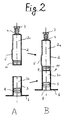
- FIG. 2 shows in section A the two partial cylinders 2, 3 of the syringe cylinder 1 of FIG. 1 in the separated state.
- the two partial cylinders - as in FIG. 1 - are then assembled in the joining plane F-F.
- the double-chamber syringe according to the invention allows separate filling of the two chambers, so that there is practically no risk of "cross contamination". Only one chamber requires special treatment when filling, e.g. if the corresponding component is a lyophilisate, then only the relevant partial cylinder and not the entire syringe cylinder needs to be treated, which significantly increases the economy of the manufacturing process, especially if special treatment devices are required that require dense stacking in the treatment room or their economical mode of operation largely depends on the full utilization of the treatment room.
- a system is, for example, a lyophylizer.
- section A shows, the partial cylinder 2 is closed at the front end with the covered syringe head 4/7. The back end is closed after filling the chamber 2a with the intermediate plug 11.
- the partial cylinder 2 forms an all around in this state closed container.
- the partial cylinder 3 is closed at the handle end with the injection piston 8.
- the chamber 3a can be filled through the open, upper end of the partial cylinder.
- the part cylinder is placed in the joining plane FF on the lower part cylinder 3 and fastened with it.
- the complete syringe body according to section B of FIG. 2 then results.
- the partial cylinder 3 can also be placed on the all-round closed partial cylinder 2 without the injection plunger and assembled with it, then - in the reverse position as shown in FIG. 2A - filled and then closed with the injection plunger 8.
- the partial cylinder - separately or combined with the partial cylinder 3 - can also be filled from the syringe head if this permits the formation of the syringe head. It is also possible to combine the measures described on the part cylinders in the course of joining the two parts. Depending on the specific structure (material) of the syringe parts, the manufacturing process used or the components to be introduced, the person skilled in the art will select the method which is favorable for the case.
- FIG. 3 shows a further embodiment of the syringe body according to the invention according to FIG. 1 in the exploded representation of FIG. 2.
- the same parts have the same reference numerals.
- the end of the partial cylinder 3 facing the joining plane FF which is still open in FIGS. 1/2, is closed after filling by means of an additional auxiliary plug 13.
- both partial cylinders - that is to say chambers - can be filled and closed completely separately (section A) and then as containers closed on all sides - as indicated by the arrows - to form the syringe head (section B).
- the partial cylinders can be filled from both ends of the partial cylinder in several possible combinations.
- Fig. 3 allows more degrees of freedom when filling and assembling the syringe.
- a finished, separately treated lyophilisate is enclosed, while in the chamber 3a a solvent is completely enclosed. This makes it possible to terminally sterilize the solvent for the two-chamber syringe.
- both partial cylinders can either be made of glass or plastic.
- a combination of both materials is also possible, i.e. one part cylinder is made of glass, the other of plastic.
- bypass 5 is possible.
- a bypass can be provided according to FIG. 4 without expanding the cylinder diameter.
- Protuberances prevent the syringe barrels from being ideally packed and they must be placed in specially made devices during treatment. These disadvantages are prevented by the bypass formation according to FIG. 4.
- Section A shows in section A a partial longitudinal section through the front partial cylinder 2 with inserted intermediate piston 11.
- Section B shows a section along line BB of section A.
- the inner wall of the partial cylinder 2 has in the bypass section at least one recess 5 (groove, groove, etc.) extending in the axial direction, which forms the bypass.
- the plastic part cylinders are preferably coated on the inside or outside in order to improve the barrier properties.
- This coating is shown again schematically in FIG. 5.
- the wall of the plastic part cylinder 2 and / or 3 is provided on the inside (section A) or outside (section B) with a layer 14. It is also conceivable to apply such a layer 14 to the cylinder wall both inside and outside.
- the layer can consist of metallic, ceramic or a glassy material.
- FIG. 6 shows an embodiment in which the two partial cylinders 2, 3 are connected to one another by an adhesive bond in the joining plane F-F.
- the end faces of the two partial cylinders are chamfered to form an adhesive groove 15.
- This adhesive bonding technique is particularly suitable when both partial cylinders are made of either glass or plastic.
- FIG. 7 shows an embodiment in which the two partial cylinders 2, 3 are connected to one another in the joining plane F-F by a weld seam 16. This connection technique can be used if both part cylinders are made of plastic.
- the two partial cylinders are connected to one another by a sealing snap connection, that is to say in a form-fitting manner.
- both part cylinders 2, 3 each have a flange 17, 17a on the end face of the joining plane for receiving a closure ring 18 made of plastic.
- This plastic ring has an undercut 19 which snaps over the lower flange 17a.
- a seal 20 made of a suitable material is arranged between the two flanges.
- the upper part cylinder 2 as in FIG. 8 is made of glass and also has a flange 17.
- the lower part cylinder 3 is made of plastic and has an integrally formed snap closure collar 21 with a flange-like joining shoulder 22 and an undercut 23 which snap-fits around the flange 17 of the upper partial cylinder when being assembled.
- a seal 20 is also provided between the support shoulder 22 and the flange 17. It is preferably a thermoplastic plastic seal that is produced together with the plastic part cylinder in a two-component injection molding process.
- FIGS. 10 and 11 show two possibilities for forming and closing the syringe head, the closing being shown in two positions A and B, respectively.
- the illustrated embodiments are particularly suitable if a lyophilisate is filled in the front chamber 2a. During lyophilization, there must be a connection to the environment so that the vapors can escape from the syringe barrel.
- FIG. 10 shows - in an enlarged view - the conically tapering syringe head 4 with the sealing cap (tip cap) 7.
- This sealing cap has axially extending recesses 24, via which in the position of the sealing cap according to section A, that is to say not completely patch cap 7, a connection of the chamber 2a of the front cylinder 2 with the environment.
- the syringe barrel i.e. the front partial cylinder 2 into a mouthpiece 25, which has an essentially cylindrical inner contour and an edge bead reinforced to form an outer collar 26.
- a plug 27 made of elastic sealing material with a recess 28 is inserted into this mouthpiece, with the section A of the figure showing the position of the plug that is not fully inserted. In this position there is a connection between the surroundings and the inside of the syringe.
- the stopper is fully inserted and flanged with an aluminum cap 29, which seals the finished lyophilisate tightly.
- a needle cap 30, in which an injection needle 31 is fastened, is placed on the syringe head.
- the needle cover has two guide sections 32 and 33, of which the section 32 for the flanged outer collar and the section 33 for the partial cylinder 2 are of the same diameter. These sections are used for guidance when the needle cover is pushed onto the syringe body, during which the needle 31 pierces the stopper 27 and the syringe is ready for application.
- a preferred method for producing and filling the pre-filled syringes shown is that first the two partial cylinders of the syringe body are manufactured, then the chambers formed by the partial cylinders are filled, optionally lyophilized and sealed, and only then are the two partial cylinders joined together.
- both partial cylinders are made of plastic, which are injection molded in the clean room, then sterilized in a hermetic packaging, and, if the two chambers formed by the partial cylinders are then filled separately, possibly lyophilized and sealed, only then can the two partial cylinders be joined together.
Landscapes
- Health & Medical Sciences (AREA)
- Vascular Medicine (AREA)
- Engineering & Computer Science (AREA)
- Anesthesiology (AREA)
- Biomedical Technology (AREA)
- Heart & Thoracic Surgery (AREA)
- Hematology (AREA)
- Life Sciences & Earth Sciences (AREA)
- Animal Behavior & Ethology (AREA)
- General Health & Medical Sciences (AREA)
- Public Health (AREA)
- Veterinary Medicine (AREA)
- Infusion, Injection, And Reservoir Apparatuses (AREA)
- Containers And Plastic Fillers For Packaging (AREA)
- Basic Packing Technique (AREA)
Applications Claiming Priority (2)
| Application Number | Priority Date | Filing Date | Title |
|---|---|---|---|
| DE4445969A DE4445969C1 (de) | 1994-12-22 | 1994-12-22 | Spritzenzylinder für eine Zweikammer-Fertigspritze, Zweikammer-Fertigspritze und Verfahren zum Herstellen und Füllen derselben |
| DE4445969 | 1994-12-22 |
Publications (3)
| Publication Number | Publication Date |
|---|---|
| EP0718002A2 true EP0718002A2 (fr) | 1996-06-26 |
| EP0718002A3 EP0718002A3 (fr) | 1996-07-03 |
| EP0718002B1 EP0718002B1 (fr) | 1998-12-23 |
Family
ID=6536709
Family Applications (1)
| Application Number | Title | Priority Date | Filing Date |
|---|---|---|---|
| EP95118594A Expired - Lifetime EP0718002B1 (fr) | 1994-12-22 | 1995-11-25 | Seringue à deux compartiments et procédé de fabrication et de remplissage |
Country Status (4)
| Country | Link |
|---|---|
| US (1) | US5788670A (fr) |
| EP (1) | EP0718002B1 (fr) |
| JP (1) | JPH08224305A (fr) |
| DE (2) | DE4445969C1 (fr) |
Cited By (9)
| Publication number | Priority date | Publication date | Assignee | Title |
|---|---|---|---|---|
| WO2001019428A2 (fr) | 1999-09-13 | 2001-03-22 | Vitro Diagnostics, Inc. | Entraineur de seringue multi-dose |
| US7998106B2 (en) | 2004-05-03 | 2011-08-16 | Thorne Jr Gale H | Safety dispensing system for hazardous substances |
| US8002734B2 (en) | 2005-08-13 | 2011-08-23 | Boehringer Ingelheim International Gmbh | Dual chamber container and process for its filling up |
| US8096971B2 (en) | 2005-08-13 | 2012-01-17 | Boehringer Ingelheim International Gmbh | Dual chamber container for lyophilization, process for the filling up and use thereof |
| WO2016109339A1 (fr) | 2014-12-30 | 2016-07-07 | 3M Innovative Properties Company | Récipient pour mélanger et distribuer des composants de médicament liquides |
| WO2016109342A1 (fr) | 2014-12-30 | 2016-07-07 | 3M Innovative Properties Company | Récipient pour mélanger et distribuer des composants |
| WO2016109336A1 (fr) | 2014-12-30 | 2016-07-07 | 3M Innovative Properties Company | Récipient pour mélanger et distribuer deux composants |
| EP3189867A1 (fr) * | 2016-01-06 | 2017-07-12 | Tecpharma Licensing AG | Procédé de fabrication de pièces et assemblage de pièces pour un dispositif d'injection par moulage par injection à deux composants |
| US10765811B2 (en) | 2014-12-08 | 2020-09-08 | Genentech, Inc. | Versatile syringe platform |
Families Citing this family (139)
| Publication number | Priority date | Publication date | Assignee | Title |
|---|---|---|---|---|
| US6964798B2 (en) | 1993-11-16 | 2005-11-15 | Baxter International Inc. | Multi-layered polymer based thin film structure for medical grade products |
| US6681810B2 (en) | 1994-12-20 | 2004-01-27 | Aradigm Corporation | Filling device for a needleless injector cartridge |
| WO2000071185A2 (fr) * | 1999-05-19 | 2000-11-30 | Weston Medical Ltd | Capsule de medicament pour injecteur sans aiguille |
| EP0892736B1 (fr) | 1996-04-02 | 2000-08-30 | Weston Medical Limited | Procede pour remplir une capsule avec un medicament et produit resultant |
| JP3298817B2 (ja) * | 1996-10-28 | 2002-07-08 | 株式会社大協精工 | ルアーロック部を有する注射器 |
| DE19753766A1 (de) * | 1997-12-04 | 1999-06-17 | Schott Glas | Länglicher Kunststoff-Hohlkörper und Verfahren zu seiner Herstellung |
| DE19835749C1 (de) * | 1998-08-07 | 2000-02-03 | Dieter Perthes | Fertig-Spritze für nicht-stabile Arzneimittel |
| US20050197626A1 (en) * | 1998-10-29 | 2005-09-08 | Medtronic Minimed Inc. | Fluid reservoir for use with an external infusion device |
| US6297322B1 (en) | 1999-09-09 | 2001-10-02 | Baxter International Inc. | Cycloolefin blends and method for solvent bonding polyolefins |
| US6613187B1 (en) | 1999-09-09 | 2003-09-02 | Baxter International Inc | Solvent bonding method for polyolefin materials |
| US6632318B1 (en) | 1999-09-09 | 2003-10-14 | Baxter International Inc. | Method for solvent bonding polyolefins |
| US6255396B1 (en) | 1999-09-09 | 2001-07-03 | Baxter International Inc. | Cycloolefin blends and method for solvent bonding polyolefins |
| US6590033B2 (en) | 1999-09-09 | 2003-07-08 | Baxter International Inc. | Cycloolefin blends and method for solvent bonding polyolefins |
| US20020055708A1 (en) * | 1999-09-24 | 2002-05-09 | Peterson Kenneth R. | Coupling syringe system and methods for obtaining a mixed composition |
| US8226598B2 (en) | 1999-09-24 | 2012-07-24 | Tolmar Therapeutics, Inc. | Coupling syringe system and methods for obtaining a mixed composition |
| US6673035B1 (en) * | 1999-10-22 | 2004-01-06 | Antares Pharma, Inc. | Medical injector and medicament loading system for use therewith |
| US6432697B1 (en) * | 2000-02-03 | 2002-08-13 | Becton, Dickinson And Company | Transparent sample container |
| US6497676B1 (en) | 2000-02-10 | 2002-12-24 | Baxter International | Method and apparatus for monitoring and controlling peritoneal dialysis therapy |
| US6566144B1 (en) | 2000-03-27 | 2003-05-20 | Atrix Laboratories | Cover plate for use in lyophilization |
| US6626870B1 (en) * | 2000-03-27 | 2003-09-30 | Artix Laboratories, Inc. | Stoppering method to maintain sterility |
| SE0001894D0 (sv) * | 2000-05-22 | 2000-05-22 | Pharmacia & Upjohn Ab | Medical device |
| US6740062B2 (en) * | 2000-05-22 | 2004-05-25 | Pharmacia Ab | Medical device |
| US6440101B1 (en) * | 2000-05-31 | 2002-08-27 | Abbott Laboratories | Syringe systems for lyophilized drugs and methods for making the same |
| US6372848B1 (en) | 2000-10-10 | 2002-04-16 | Baxter International Inc. | Blend of ethylene and α-olefin copolymers obtained using a metallocene catalyst for fabricating medical films and tubings |
| FR2822710B1 (fr) * | 2001-03-27 | 2004-04-02 | Lab Contactologie Appl Lca | Seringue pour solutions viscoleastiques |
| US20030125662A1 (en) | 2002-01-03 | 2003-07-03 | Tuan Bui | Method and apparatus for providing medical treatment therapy based on calculated demand |
| CA2475573C (fr) | 2002-02-11 | 2013-03-26 | Antares Pharma, Inc. | Injecteur intradermique |
| US6743194B2 (en) * | 2002-03-28 | 2004-06-01 | Igal Sharon | Multi-compartment syringe |
| US7238164B2 (en) | 2002-07-19 | 2007-07-03 | Baxter International Inc. | Systems, methods and apparatuses for pumping cassette-based therapies |
| US7135027B2 (en) * | 2002-10-04 | 2006-11-14 | Baxter International, Inc. | Devices and methods for mixing and extruding medically useful compositions |
| US6866653B2 (en) * | 2002-10-31 | 2005-03-15 | Kyongtae T. Bae | Method and apparatus for sequential delivery of multiple injectable substances stored in a prefilled syringe |
| FR2847887A1 (fr) * | 2002-12-02 | 2004-06-04 | Valois Sas | Reservoir de produits fluides |
| US20060104968A1 (en) | 2003-03-05 | 2006-05-18 | Halozyme, Inc. | Soluble glycosaminoglycanases and methods of preparing and using soluble glycosaminogly ycanases |
| US20050075611A1 (en) * | 2003-10-01 | 2005-04-07 | Hetzler Kevin G. | Low extractable, thermoplastic syringe and tip cap |
| CN100488580C (zh) * | 2003-10-01 | 2009-05-20 | 贝克顿·迪金森公司 | 可萃取物低的热塑性注射器和针尖盖帽 |
| US7677419B2 (en) * | 2004-04-21 | 2010-03-16 | Nordson Corporation | Syringes and methods of syringe manufacturing |
| MXPA06011837A (es) | 2004-04-27 | 2007-01-16 | Baxter Int | Sistema de reactor de tanque agitado. |
| SE0401569D0 (sv) * | 2004-06-17 | 2004-06-17 | Gambro Lundia Ab | Applikator |
| JP2006006791A (ja) * | 2004-06-29 | 2006-01-12 | Daikyo Seiko Ltd | 容器兼用注射器の注射ノズル用密封ゴム栓 |
| IL162854A (en) | 2004-07-04 | 2011-08-31 | Igal Sharon | Syringe assembly |
| US20060084909A1 (en) * | 2004-07-12 | 2006-04-20 | Chung Yuan Christian University | Syringe with separate cavities |
| AT500930B1 (de) * | 2004-10-25 | 2007-03-15 | Pharma Consult Ges M B H & Co | Verfahren und vorrichtung zum lyophilisieren, rekonstituieren und verabreichen eines rekonstituierten wirkstoffes |
| DE102004056617A1 (de) * | 2004-11-24 | 2006-06-01 | Arthur Fabian | Medizinische Doppelkammer-Spritze aus Kunststoff |
| US20060178644A1 (en) * | 2004-12-03 | 2006-08-10 | Reynolds David L | Pharmaceutical cartridge assembly and method of filling same |
| CN101132820B (zh) | 2005-01-24 | 2010-05-19 | 安塔雷斯制药公司 | 预充式针辅助喷射注入器 |
| JP2008540039A (ja) * | 2005-05-16 | 2008-11-20 | マリンクロッド・インコーポレイテッド | マルチステージ注射器、およびこれを使用する方法 |
| DE102005038458A1 (de) * | 2005-08-13 | 2007-02-15 | Boehringer Ingelheim Pharma Gmbh & Co. Kg | Doppelkammer-Behälter ohne Bypass im zylindrischen Körper |
| DE102005038497A1 (de) * | 2005-08-13 | 2007-02-15 | Boehringer Ingelheim Pharma Gmbh & Co. Kg | Doppelkammer-Behälter ohne Bypass |
| DK1973475T3 (da) * | 2006-01-17 | 2010-10-18 | Baxter Int | Blandeindretning, -system og -fremgangsmåde |
| US20090038701A1 (en) | 2006-01-17 | 2009-02-12 | Baxter International Inc. | Device, system and method for mixing |
| WO2007131013A1 (fr) | 2006-05-03 | 2007-11-15 | Antares Pharma, Inc. | Injecteur de reconstitution à deux étages |
| DE202006018609U1 (de) * | 2006-08-29 | 2007-05-16 | Euro-Celtique S.A. | Verwendung von Opioidformulierungen in nadellosen Vorrichtungen zur Medikamentenverabreichung |
| US8558964B2 (en) | 2007-02-15 | 2013-10-15 | Baxter International Inc. | Dialysis system having display with electromagnetic compliance (“EMC”) seal |
| US8870812B2 (en) | 2007-02-15 | 2014-10-28 | Baxter International Inc. | Dialysis system having video display with ambient light adjustment |
| US8361023B2 (en) | 2007-02-15 | 2013-01-29 | Baxter International Inc. | Dialysis system with efficient battery back-up |
| US7731689B2 (en) | 2007-02-15 | 2010-06-08 | Baxter International Inc. | Dialysis system having inductive heating |
| US7998115B2 (en) | 2007-02-15 | 2011-08-16 | Baxter International Inc. | Dialysis system having optical flowrate detection |
| DE102007014281A1 (de) * | 2007-03-19 | 2008-09-25 | Schott Ag | Verfahren zur Herstellung einer Mehrkammer-Spritze mit Bypasskanal |
| US20080255520A1 (en) * | 2007-04-11 | 2008-10-16 | Henderson Thomas D | Multiple injection syringe holder |
| US20080275387A1 (en) * | 2007-05-03 | 2008-11-06 | Yeadon Stephen C | Hemostatic medical device |
| WO2008151737A1 (fr) * | 2007-06-14 | 2008-12-18 | Sanofi-Aventis Deutschland Gmbh | Ampoule à deux chambres |
| DK2167169T4 (en) | 2007-06-14 | 2016-05-30 | Sanofi Aventis Deutschland | Tokammerkarpule with accessories |
| CA2639729A1 (fr) * | 2007-09-27 | 2009-03-27 | Tyco Healthcare Group Lp | Dispositif etage d'administration de liquide et methode d'utilisation |
| US8231568B2 (en) * | 2007-10-16 | 2012-07-31 | Nordson Corporation | Syringes with a reduced susceptibility to freeze-thaw void formation and methods of manufacturing such syringes |
| JP5109596B2 (ja) * | 2007-11-01 | 2012-12-26 | ニプロ株式会社 | キャップ |
| TWI395593B (zh) | 2008-03-06 | 2013-05-11 | Halozyme Inc | 可活化的基質降解酵素之活體內暫時性控制 |
| DE102008030268B3 (de) * | 2008-06-19 | 2010-02-04 | Arzneimittel Gmbh Apotheker Vetter & Co. Ravensburg | Verfahren zum Befüllen von Doppelkammersystemen in vorsterilisierbaren Trägersystemen und vorsterilisierbares Trägersystem |
| DE102008030267B3 (de) | 2008-06-19 | 2010-01-28 | Arzneimittel Gmbh Apotheker Vetter & Co. Ravensburg | Verfahren zum Befüllen von Doppelkammersystemen in vorsterilisierbaren Trägersystemen und vorsterilisierbares Trägersystem |
| US8142403B2 (en) * | 2008-06-30 | 2012-03-27 | Tyco Healthcare Group Lp | Syringe assembly with plunger having a secondary dispensing reservoir |
| EP3581224A1 (fr) | 2008-08-05 | 2019-12-18 | Antares Pharma, Inc. | Injecteur à dosage multiple |
| US8152778B2 (en) * | 2008-09-30 | 2012-04-10 | Tyco Healthcare Group Lp | Device for interfacing with standard luer lock syringes |
| US8728054B2 (en) | 2008-10-29 | 2014-05-20 | Synchrojet Llc | Syringe-carpule assembly |
| EP2403523A1 (fr) | 2009-03-06 | 2012-01-11 | Halozyme, Inc. | Mutants thermosensibles de métalloprotéase matricielle 1 et leurs utilisations |
| AU2010226442A1 (en) | 2009-03-20 | 2011-10-13 | Antares Pharma, Inc. | Hazardous agent injection system |
| US20100246316A1 (en) * | 2009-03-31 | 2010-09-30 | Baxter International Inc. | Dispenser, kit and mixing adapter |
| WO2013170052A1 (fr) | 2012-05-09 | 2013-11-14 | Sio2 Medical Products, Inc. | Enrobage protecteur en saccharide pour conditionnement pharmaceutique |
| US7985188B2 (en) | 2009-05-13 | 2011-07-26 | Cv Holdings Llc | Vessel, coating, inspection and processing apparatus |
| MX350703B (es) | 2009-05-13 | 2017-09-14 | Sio2 Medical Products Inc | Metodo de gasificacion para inspeccionar una superficie revestida. |
| US9458536B2 (en) | 2009-07-02 | 2016-10-04 | Sio2 Medical Products, Inc. | PECVD coating methods for capped syringes, cartridges and other articles |
| CA2766229A1 (fr) | 2009-09-08 | 2011-03-17 | Baxter International Inc. | Systeme de reconstitution et d'application de produit de fermeture de plaie |
| EP2480271A2 (fr) * | 2009-09-22 | 2012-08-01 | Medmix Systems AG | Contenant scellé pourvu d'un piston coulissant |
| US8641661B2 (en) * | 2010-01-05 | 2014-02-04 | Baxter International Inc. | Mixing system, kit and mixer adapter |
| CA2726566A1 (fr) * | 2010-01-11 | 2011-07-11 | Baxter International Inc. | Systeme de pipettage, pointe de pipette et trousse connexe |
| WO2011117877A1 (fr) * | 2010-03-22 | 2011-09-29 | Pawan Trilokchand Agrawal | Seringue pré-remplie à chambre double |
| RU2440151C1 (ru) * | 2010-04-27 | 2012-01-20 | Владимир Васильевич Агеев | Одноразовый шприц-картридж с подвижной иглой (варианты) |
| US11624115B2 (en) | 2010-05-12 | 2023-04-11 | Sio2 Medical Products, Inc. | Syringe with PECVD lubrication |
| PL2601105T3 (pl) * | 2010-08-06 | 2018-03-30 | Hospira Australia Pty Ltd | Sposób i system przygotowania fiolki |
| US9878101B2 (en) | 2010-11-12 | 2018-01-30 | Sio2 Medical Products, Inc. | Cyclic olefin polymer vessels and vessel coating methods |
| EP2648782A1 (fr) | 2010-12-06 | 2013-10-16 | Novo Nordisk Health Care AG | Dispositif d'administration de médicaments actionné par une molette |
| WO2012085208A1 (fr) | 2010-12-23 | 2012-06-28 | Novo Nordisk A/S | Système d'entraînement de tige de piston pour un dispositif d'administration de médicament |
| EP2667856B9 (fr) | 2011-01-24 | 2021-12-01 | Otsuka Pharmaceutical Co., Ltd. | Dispositif médical contenant une composition de gâteau comprenant de l'aripiprazole comme ingrédient actif, et composition de gâteau comprenant de l'aripiprazole comme ingrédient actif |
| WO2012109387A1 (fr) | 2011-02-08 | 2012-08-16 | Halozyme, Inc. | Composition et formulation lipidique d'une enzyme dégradant le hyaluronane et son utilisation pour le traitement de l'hyperplasie bénigne de la prostate |
| US9566540B2 (en) * | 2011-03-29 | 2017-02-14 | Emd Millipore Corporation | Method and device for centrifugation and filtration |
| US9272095B2 (en) | 2011-04-01 | 2016-03-01 | Sio2 Medical Products, Inc. | Vessels, contact surfaces, and coating and inspection apparatus and methods |
| US8496619B2 (en) | 2011-07-15 | 2013-07-30 | Antares Pharma, Inc. | Injection device with cammed ram assembly |
| US9220660B2 (en) | 2011-07-15 | 2015-12-29 | Antares Pharma, Inc. | Liquid-transfer adapter beveled spike |
| US9022995B2 (en) | 2011-08-01 | 2015-05-05 | Synchrojet Llc | Stopper/plunger for carpules of syringe-carpule assembly |
| WO2013040501A1 (fr) | 2011-09-16 | 2013-03-21 | Pharmathene, Inc. | Compositions et combinaisons d'accepteurs biologiques organophosphorés et d'enzymes dégradant le hyaluronane, et leurs utilisations |
| US8911395B2 (en) | 2011-11-01 | 2014-12-16 | George Just | Syringe carpule for storing, transporting and in situ mixing of lidocaine and sodium bicarbonate and delivery of buffered anesthetic solution |
| US9616176B2 (en) | 2011-11-01 | 2017-04-11 | George Just | Syringe carpule for storing, transporting and in situ mixing of local anesthetic and buffer, and for delivery of buffered anesthetic solution and a piercing-mixing unit therefore |
| EP2776603B1 (fr) | 2011-11-11 | 2019-03-06 | SiO2 Medical Products, Inc. | Revêtement de passivation, de protection de ph ou à pouvoir lubrifiant pour conditionnement pharmaceutique, processus et appareil de revêtement |
| US11116695B2 (en) | 2011-11-11 | 2021-09-14 | Sio2 Medical Products, Inc. | Blood sample collection tube |
| WO2013106845A1 (fr) * | 2012-01-13 | 2013-07-18 | Medpro Safety Products, Inc. | Cartouche de fluide pré-remplie et procédés de remplissage |
| US8834449B2 (en) | 2012-01-23 | 2014-09-16 | Ikomed Technologies, Inc. | Mixing syringe |
| US9751056B2 (en) | 2012-01-23 | 2017-09-05 | Merit Medical Systems, Inc. | Mixing syringe |
| JP6457383B2 (ja) | 2012-04-06 | 2019-01-23 | アンタレス・ファーマ・インコーポレーテッド | テストステロン組成物の針支援式ジェット注入投与 |
| US9364610B2 (en) | 2012-05-07 | 2016-06-14 | Antares Pharma, Inc. | Injection device with cammed ram assembly |
| US20150297800A1 (en) | 2012-07-03 | 2015-10-22 | Sio2 Medical Products, Inc. | SiOx BARRIER FOR PHARMACEUTICAL PACKAGE AND COATING PROCESS |
| CA2890066C (fr) | 2012-11-01 | 2021-11-09 | Sio2 Medical Products, Inc. | Procedes d'inspection de revetement |
| US9903782B2 (en) | 2012-11-16 | 2018-02-27 | Sio2 Medical Products, Inc. | Method and apparatus for detecting rapid barrier coating integrity characteristics |
| JP6382830B2 (ja) | 2012-11-30 | 2018-08-29 | エスアイオーツー・メディカル・プロダクツ・インコーポレイテッド | 医療シリンジ、カートリッジ等上でのpecvd堆積の均一性制御 |
| US9764093B2 (en) | 2012-11-30 | 2017-09-19 | Sio2 Medical Products, Inc. | Controlling the uniformity of PECVD deposition |
| WO2014093926A1 (fr) | 2012-12-14 | 2014-06-19 | Larson Bryan | Carpule de médicament double pour seringues dentaires |
| EP4349383A3 (fr) | 2013-02-11 | 2024-06-19 | Antares Pharma, Inc. | Dispositif d'injection par jet assisté par aiguille ayant une force de déclenchement réduite |
| JP5437510B1 (ja) * | 2013-02-15 | 2014-03-12 | 株式会社アルテ | 二室式容器兼用注射器 |
| US9662450B2 (en) | 2013-03-01 | 2017-05-30 | Sio2 Medical Products, Inc. | Plasma or CVD pre-treatment for lubricated pharmaceutical package, coating process and apparatus |
| US9937099B2 (en) | 2013-03-11 | 2018-04-10 | Sio2 Medical Products, Inc. | Trilayer coated pharmaceutical packaging with low oxygen transmission rate |
| EP2968792B1 (fr) | 2013-03-11 | 2019-05-15 | Antares Pharma, Inc. | Injecteur de dose avec système à pignon |
| EP2971228B1 (fr) | 2013-03-11 | 2023-06-21 | Si02 Medical Products, Inc. | Emballage revêtu |
| US20160030672A1 (en) * | 2013-03-15 | 2016-02-04 | Sanofi-Aventis Deutschland Gmbh | Body Party and Diaphragm Materials for Medical Devices |
| US20160017490A1 (en) | 2013-03-15 | 2016-01-21 | Sio2 Medical Products, Inc. | Coating method |
| JP2016533210A (ja) | 2013-10-15 | 2016-10-27 | エスアイオーツー・メディカル・プロダクツ・インコーポレイテッド | 射出成形壁構造体のための方法及び装置 |
| KR102372700B1 (ko) * | 2013-11-27 | 2022-03-08 | 니프로 가부시키가이샤 | 프리필드 시린지 |
| USD755957S1 (en) | 2013-12-13 | 2016-05-10 | Bryan Larson | Dental carpule |
| WO2015148471A1 (fr) | 2014-03-28 | 2015-10-01 | Sio2 Medical Products, Inc. | Revêtements antistatiques pour des récipients en plastique |
| EP3011990A1 (fr) | 2014-10-21 | 2016-04-27 | Sulzer Mixpac AG | Seringue à deux compartiments |
| EP3025744A1 (fr) | 2014-11-28 | 2016-06-01 | Sulzer Mixpac AG | Appareil et procédés pour stocker et mélanger des substances séparées |
| EP3028946A1 (fr) * | 2014-12-05 | 2016-06-08 | F. Hoffmann-La Roche AG | Préparation d'un conteneur à chambre double |
| EP3337915B1 (fr) | 2015-08-18 | 2021-11-03 | SiO2 Medical Products, Inc. | Conditionnement pharmaceutique et autre présentant un faible taux de transmission d'oxygène |
| CN108025136B (zh) * | 2015-09-11 | 2020-10-23 | 西医药服务有限公司 | 具有凹槽的医疗施用筒和密封其的方法 |
| IT201700039712A1 (it) * | 2017-04-11 | 2018-10-11 | Orofino Pharmaceuticals Group Srl | Dispositivo di iniezione pre-riempito |
| US11179516B2 (en) | 2017-06-22 | 2021-11-23 | Baxter International Inc. | Systems and methods for incorporating patient pressure into medical fluid delivery |
| CN108421132B (zh) * | 2018-03-11 | 2024-04-12 | 杨一博 | 药物复原装置 |
| DE202018105835U1 (de) | 2018-10-11 | 2018-11-09 | Schott Schweiz Ag | Spritzenkörper |
| JP7217003B2 (ja) * | 2019-02-08 | 2023-02-02 | ナミックス株式会社 | 樹脂組成物充填済みシリンジ及びその保存方法 |
| EP3862415A1 (fr) * | 2020-02-04 | 2021-08-11 | Sensirion AG | Procédé, dispositif, cartouche de capteur et kit de pièces pour la culture et la détection de micro-organismes |
| DE102020118520A1 (de) | 2020-07-14 | 2022-01-20 | Adiplast Gmbh | Vorrichtung und verfahren zum injizieren eines wirkstoffs, bevorzugt von neurotoxin, besonders bevorzugt von botulinumtoxin |
| EP4455590A1 (fr) | 2023-04-28 | 2024-10-30 | NerPharMa S.r.l. | Procédé de lyophilisation rapide |
| WO2025181800A1 (fr) * | 2024-02-29 | 2025-09-04 | Dali Medical Devices Ltd | Récipient à double chambre et ses procédés d'utilisation |
Family Cites Families (11)
| Publication number | Priority date | Publication date | Assignee | Title |
|---|---|---|---|---|
| FR1099362A (fr) * | 1954-04-23 | 1955-09-05 | D Antibiotiques Et De Biolog L | Seringue-capsule pour des médicaments qui doivent seulement être mélangés au moment de l'emploi |
| NL180634C (nl) * | 1977-12-23 | 1987-04-01 | Duphar Int Res | Injectiespuit alsmede naaldhouder hiervoor. |
| EP0207544B1 (fr) * | 1985-06-27 | 1990-09-26 | Duphar International Research B.V | Seringue à plusieurs compartiments |
| US4613326A (en) * | 1985-07-12 | 1986-09-23 | Becton, Dickinson And Company | Two-component medication syringe assembly |
| DE3816961A1 (de) * | 1987-07-21 | 1989-02-02 | Wasserburger Arzneimittelwerk | Injektionsspritze fuer medizinische zwecke |
| DE3736343C2 (de) * | 1987-10-27 | 1996-07-18 | Wasserburger Arzneimittelwerk | Injektionsspritze |
| ATE67415T1 (de) * | 1988-02-16 | 1991-10-15 | Vetter & Co Apotheker | Spritze fuer medizinische zwecke. |
| FR2672868B1 (fr) * | 1991-02-15 | 1993-06-04 | Pasteur Merieux Serums Vacc | Procede de conditionnement de vaccins lyophilises en seringue et bouchon pour sa mise en óoeuvre. |
| JPH0614756Y2 (ja) * | 1991-06-26 | 1994-04-20 | 株式会社アルテ | 組み立て式の2室式容器兼用注射器 |
| JP3172005B2 (ja) * | 1992-11-27 | 2001-06-04 | 株式会社大協精工 | 注射器兼容器 |
| US5607400A (en) * | 1995-05-19 | 1997-03-04 | Becton, Dickinson And Company | Pre-fillable syringe and stopper assembly therefor |
-
1994
- 1994-12-22 DE DE4445969A patent/DE4445969C1/de not_active Expired - Fee Related
-
1995
- 1995-11-25 DE DE59504627T patent/DE59504627D1/de not_active Expired - Lifetime
- 1995-11-25 EP EP95118594A patent/EP0718002B1/fr not_active Expired - Lifetime
- 1995-12-22 JP JP7335309A patent/JPH08224305A/ja active Pending
- 1995-12-22 US US08/577,309 patent/US5788670A/en not_active Expired - Lifetime
Cited By (14)
| Publication number | Priority date | Publication date | Assignee | Title |
|---|---|---|---|---|
| WO2001019428A2 (fr) | 1999-09-13 | 2001-03-22 | Vitro Diagnostics, Inc. | Entraineur de seringue multi-dose |
| US7998106B2 (en) | 2004-05-03 | 2011-08-16 | Thorne Jr Gale H | Safety dispensing system for hazardous substances |
| US8002734B2 (en) | 2005-08-13 | 2011-08-23 | Boehringer Ingelheim International Gmbh | Dual chamber container and process for its filling up |
| US8096971B2 (en) | 2005-08-13 | 2012-01-17 | Boehringer Ingelheim International Gmbh | Dual chamber container for lyophilization, process for the filling up and use thereof |
| US11633545B2 (en) | 2014-12-08 | 2023-04-25 | Genentech, Inc. | Versatile syringe platform |
| US10765811B2 (en) | 2014-12-08 | 2020-09-08 | Genentech, Inc. | Versatile syringe platform |
| WO2016109336A1 (fr) | 2014-12-30 | 2016-07-07 | 3M Innovative Properties Company | Récipient pour mélanger et distribuer deux composants |
| KR20170100626A (ko) * | 2014-12-30 | 2017-09-04 | 쓰리엠 이노베이티브 프로퍼티즈 컴파니 | 성분들을 혼합 및 분배하기 위한 용기 |
| US10327990B2 (en) | 2014-12-30 | 2019-06-25 | 3M Innovative Properties Company | Container for mixing and dispensing fluid medication components |
| US10507286B2 (en) | 2014-12-30 | 2019-12-17 | 3M Innovative Properties Company | Container for mixing and dispensing two components |
| US10744265B2 (en) | 2014-12-30 | 2020-08-18 | Kindeva Drug Delivery L.P. | Container for mixing and dispensing components |
| WO2016109342A1 (fr) | 2014-12-30 | 2016-07-07 | 3M Innovative Properties Company | Récipient pour mélanger et distribuer des composants |
| WO2016109339A1 (fr) | 2014-12-30 | 2016-07-07 | 3M Innovative Properties Company | Récipient pour mélanger et distribuer des composants de médicament liquides |
| EP3189867A1 (fr) * | 2016-01-06 | 2017-07-12 | Tecpharma Licensing AG | Procédé de fabrication de pièces et assemblage de pièces pour un dispositif d'injection par moulage par injection à deux composants |
Also Published As
| Publication number | Publication date |
|---|---|
| DE4445969C1 (de) | 1996-03-14 |
| EP0718002B1 (fr) | 1998-12-23 |
| EP0718002A3 (fr) | 1996-07-03 |
| US5788670A (en) | 1998-08-04 |
| JPH08224305A (ja) | 1996-09-03 |
| DE59504627D1 (de) | 1999-02-04 |
Similar Documents
| Publication | Publication Date | Title |
|---|---|---|
| DE4445969C1 (de) | Spritzenzylinder für eine Zweikammer-Fertigspritze, Zweikammer-Fertigspritze und Verfahren zum Herstellen und Füllen derselben | |
| EP2167169B1 (fr) | Ampoule à deux chambres avec garniture | |
| DE4438360C2 (de) | Vorfüllbare partikelarme, sterile Einmalspritze für die Injektion von Präparaten und Verfahren zu ihrer Herstellung | |
| DE69628772T2 (de) | Glassampulle für Injektionsspritze vorgefüllt mit flüssigem Arzneimittel | |
| EP2736814B1 (fr) | Ampoule à usage unique pour un dispositif de production d'aérosols | |
| EP2475466B1 (fr) | Dispositif de dosage pour la distribution dosée de préparations liquides, procédé de remplissage ainsi qu'utilisation d'un dispositif de dosage selon l'invention | |
| DE19652708C2 (de) | Verfahren zum Herstellen eines befüllten Kunststoff-Spritzenkorpus für medizinische Zwecke | |
| WO2008151737A1 (fr) | Ampoule à deux chambres | |
| DE69726530T2 (de) | Abdichtende Schutzbarriere für eine Spritze | |
| EP2242698B1 (fr) | Bouchon de fermeture | |
| DE3229469C2 (de) | Medizinische Spritze | |
| EP0344476A2 (fr) | Ampoule | |
| EP1566195B1 (fr) | Dispositif pour le stockage, le transport et l'administration d'un liquide preferablement medical | |
| AT500930A1 (de) | Verfahren und vorrichtung zum lyophilisieren, rekonstituieren und verabreichen eines rekonstituierten wirkstoffes | |
| EP1101505A1 (fr) | Capuchon pour une seringue pré-rempliable, à usage unique | |
| EP0788804A2 (fr) | Applicateur médical | |
| DE4323124A1 (de) | Spritze mit Zwei-Komponenten-Zylinder | |
| EP0220551A1 (fr) | Seringue pour l'application de masses dentaires et son procédé de fabrication | |
| WO2002098748A1 (fr) | Systeme de bouchage pour flacon de medicaments et procede permettant de le produire | |
| DE3716586C2 (de) | Behälter aus Kunststoff zur Aufbewahrung und Applikation eines Kathetergleitmittels und Verfahren zu seiner Herstellung | |
| EP1793882A1 (fr) | Piston pour seringue, et seringue correspondante | |
| WO2005115865A1 (fr) | Fermeture absorbant l'oxygene | |
| DE19604113C2 (de) | Einkammer-Transfersystem für Wirksubstanzen, und der daraus fertig montierte Transferbehälter | |
| WO2019097015A1 (fr) | Contenant à médicaments | |
| DE1441919C (de) | BakteiienunduicWässiget Behälter |
Legal Events
| Date | Code | Title | Description |
|---|---|---|---|
| PUAI | Public reference made under article 153(3) epc to a published international application that has entered the european phase |
Free format text: ORIGINAL CODE: 0009012 |
|
| PUAL | Search report despatched |
Free format text: ORIGINAL CODE: 0009013 |
|
| AK | Designated contracting states |
Kind code of ref document: A2 Designated state(s): CH DE FR GB IT LI |
|
| AK | Designated contracting states |
Kind code of ref document: A3 Designated state(s): CH DE FR GB IT LI |
|
| 17P | Request for examination filed |
Effective date: 19961123 |
|
| GRAG | Despatch of communication of intention to grant |
Free format text: ORIGINAL CODE: EPIDOS AGRA |
|
| 17Q | First examination report despatched |
Effective date: 19980116 |
|
| RAP1 | Party data changed (applicant data changed or rights of an application transferred) |
Owner name: CARL-ZEISS-STIFTUNG TRADING AS SCHOTT GLASWERKE Owner name: SCHOTT GLAS |
|
| GRAG | Despatch of communication of intention to grant |
Free format text: ORIGINAL CODE: EPIDOS AGRA |
|
| GRAH | Despatch of communication of intention to grant a patent |
Free format text: ORIGINAL CODE: EPIDOS IGRA |
|
| RAP1 | Party data changed (applicant data changed or rights of an application transferred) |
Owner name: CARL-ZEISS-STIFTUNG TRADING AS SCHOTT GLAS Owner name: SCHOTT GLAS |
|
| GRAH | Despatch of communication of intention to grant a patent |
Free format text: ORIGINAL CODE: EPIDOS IGRA |
|
| GRAA | (expected) grant |
Free format text: ORIGINAL CODE: 0009210 |
|
| AK | Designated contracting states |
Kind code of ref document: B1 Designated state(s): CH DE FR GB IT LI |
|
| REG | Reference to a national code |
Ref country code: CH Ref legal event code: EP |
|
| ITF | It: translation for a ep patent filed | ||
| REF | Corresponds to: |
Ref document number: 59504627 Country of ref document: DE Date of ref document: 19990204 |
|
| GBT | Gb: translation of ep patent filed (gb section 77(6)(a)/1977) |
Effective date: 19990122 |
|
| ET | Fr: translation filed | ||
| PLBE | No opposition filed within time limit |
Free format text: ORIGINAL CODE: 0009261 |
|
| STAA | Information on the status of an ep patent application or granted ep patent |
Free format text: STATUS: NO OPPOSITION FILED WITHIN TIME LIMIT |
|
| 26N | No opposition filed | ||
| REG | Reference to a national code |
Ref country code: GB Ref legal event code: IF02 |
|
| REG | Reference to a national code |
Ref country code: CH Ref legal event code: PUE Owner name: SCHOTT AG Free format text: SCHOTT GLAS#HATTENBERGSTRASSE 10#55122 MAINZ (DE) -TRANSFER TO- SCHOTT AG#HATTENBERGSTRASSE 10#55122 MAINZ (DE) |
|
| REG | Reference to a national code |
Ref country code: GB Ref legal event code: 732E |
|
| REG | Reference to a national code |
Ref country code: FR Ref legal event code: TP |
|
| PGFP | Annual fee paid to national office [announced via postgrant information from national office to epo] |
Ref country code: DE Payment date: 20091120 Year of fee payment: 15 Ref country code: CH Payment date: 20091124 Year of fee payment: 15 |
|
| PGFP | Annual fee paid to national office [announced via postgrant information from national office to epo] |
Ref country code: IT Payment date: 20091121 Year of fee payment: 15 Ref country code: GB Payment date: 20091119 Year of fee payment: 15 Ref country code: FR Payment date: 20091201 Year of fee payment: 15 |
|
| REG | Reference to a national code |
Ref country code: CH Ref legal event code: PL |
|
| GBPC | Gb: european patent ceased through non-payment of renewal fee |
Effective date: 20101125 |
|
| PG25 | Lapsed in a contracting state [announced via postgrant information from national office to epo] |
Ref country code: CH Free format text: LAPSE BECAUSE OF NON-PAYMENT OF DUE FEES Effective date: 20101130 Ref country code: LI Free format text: LAPSE BECAUSE OF NON-PAYMENT OF DUE FEES Effective date: 20101130 |
|
| REG | Reference to a national code |
Ref country code: DE Ref legal event code: R119 Ref document number: 59504627 Country of ref document: DE Effective date: 20110601 Ref country code: DE Ref legal event code: R119 Ref document number: 59504627 Country of ref document: DE Effective date: 20110531 |
|
| REG | Reference to a national code |
Ref country code: FR Ref legal event code: ST Effective date: 20110801 |
|
| PG25 | Lapsed in a contracting state [announced via postgrant information from national office to epo] |
Ref country code: DE Free format text: LAPSE BECAUSE OF NON-PAYMENT OF DUE FEES Effective date: 20110531 |
|
| PG25 | Lapsed in a contracting state [announced via postgrant information from national office to epo] |
Ref country code: FR Free format text: LAPSE BECAUSE OF NON-PAYMENT OF DUE FEES Effective date: 20101130 |
|
| PG25 | Lapsed in a contracting state [announced via postgrant information from national office to epo] |
Ref country code: GB Free format text: LAPSE BECAUSE OF NON-PAYMENT OF DUE FEES Effective date: 20101125 |
|
| PG25 | Lapsed in a contracting state [announced via postgrant information from national office to epo] |
Ref country code: IT Free format text: LAPSE BECAUSE OF NON-PAYMENT OF DUE FEES Effective date: 20101125 |