EP0718032A1 - Dispositif pour mélanger deux fluides en mouvement, plus particulièrement pour l'aération de moût pour la préparation de bière - Google Patents
Dispositif pour mélanger deux fluides en mouvement, plus particulièrement pour l'aération de moût pour la préparation de bière Download PDFInfo
- Publication number
- EP0718032A1 EP0718032A1 EP95117905A EP95117905A EP0718032A1 EP 0718032 A1 EP0718032 A1 EP 0718032A1 EP 95117905 A EP95117905 A EP 95117905A EP 95117905 A EP95117905 A EP 95117905A EP 0718032 A1 EP0718032 A1 EP 0718032A1
- Authority
- EP
- European Patent Office
- Prior art keywords
- nozzle body
- wort
- fluid
- area
- nozzle
- Prior art date
- Legal status (The legal status is an assumption and is not a legal conclusion. Google has not performed a legal analysis and makes no representation as to the accuracy of the status listed.)
- Withdrawn
Links
Images
Classifications
-
- B—PERFORMING OPERATIONS; TRANSPORTING
- B01—PHYSICAL OR CHEMICAL PROCESSES OR APPARATUS IN GENERAL
- B01F—MIXING, e.g. DISSOLVING, EMULSIFYING OR DISPERSING
- B01F25/00—Flow mixers; Mixers for falling materials, e.g. solid particles
- B01F25/30—Injector mixers
- B01F25/31—Injector mixers in conduits or tubes through which the main component flows
-
- B—PERFORMING OPERATIONS; TRANSPORTING
- B01—PHYSICAL OR CHEMICAL PROCESSES OR APPARATUS IN GENERAL
- B01F—MIXING, e.g. DISSOLVING, EMULSIFYING OR DISPERSING
- B01F25/00—Flow mixers; Mixers for falling materials, e.g. solid particles
- B01F25/30—Injector mixers
- B01F25/31—Injector mixers in conduits or tubes through which the main component flows
- B01F25/314—Injector mixers in conduits or tubes through which the main component flows wherein additional components are introduced at the circumference of the conduit
- B01F25/3142—Injector mixers in conduits or tubes through which the main component flows wherein additional components are introduced at the circumference of the conduit the conduit having a plurality of openings in the axial direction or in the circumferential direction
-
- B—PERFORMING OPERATIONS; TRANSPORTING
- B01—PHYSICAL OR CHEMICAL PROCESSES OR APPARATUS IN GENERAL
- B01F—MIXING, e.g. DISSOLVING, EMULSIFYING OR DISPERSING
- B01F25/00—Flow mixers; Mixers for falling materials, e.g. solid particles
- B01F25/30—Injector mixers
- B01F25/31—Injector mixers in conduits or tubes through which the main component flows
- B01F25/314—Injector mixers in conduits or tubes through which the main component flows wherein additional components are introduced at the circumference of the conduit
- B01F25/3142—Injector mixers in conduits or tubes through which the main component flows wherein additional components are introduced at the circumference of the conduit the conduit having a plurality of openings in the axial direction or in the circumferential direction
- B01F25/31423—Injector mixers in conduits or tubes through which the main component flows wherein additional components are introduced at the circumference of the conduit the conduit having a plurality of openings in the axial direction or in the circumferential direction with a plurality of perforations in the circumferential direction only and covering the whole circumference
- B01F25/314231—Injector mixers in conduits or tubes through which the main component flows wherein additional components are introduced at the circumference of the conduit the conduit having a plurality of openings in the axial direction or in the circumferential direction with a plurality of perforations in the circumferential direction only and covering the whole circumference the perforations being a complete cut-out in the circumferential direction covering the whole diameter of the tube, i.e. having two consecutive tubes placed consecutively, the additional component being introduced between them
Definitions
- the present invention relates to a device for mixing two flowing fluids, in particular for aerating wort for beer production, according to the preamble of patent claim 1.
- the invention further relates to a method for aerating wort in beer production according to the preamble of patent claim 15.
- the wort produced is fermented using yeast.
- oxygen must be added to the wort. This is usually done by introducing air into the wort between the brewhouse and the fermenting cellar.
- the required amount of oxygen is usually 7 to 10 mg / l.
- in practice up to 10 times the amount of air is required to achieve the to achieve the desired oxygen content in the wort.
- the so-called two-component nozzle (according to Prof. Chawla), which has a similar structure to the Venturi tube, is also known from Kunze, supra. However, the air is introduced into the actual mixing chamber through fine nozzles, which are distributed essentially uniformly over the entire wall.
- the device according to the invention can be used to mix any flowing fluids, that is to say gas-gas, liquid-gas or liquid-liquid, the invention is described below essentially using the example of aeration of wort.
- the device according to the invention has a nozzle body which in the longitudinal direction of the first fluid, in particular the to be aerated wort is flowed through.
- This nozzle body is provided with an essentially radial inflow opening for the second fluid, in particular the air to be supplied to the wort.
- the interior of the nozzle body In the area of the fluid inlet, based on the direction of flow of the first fluid, that is to say the wort, the interior of the nozzle body has a cross-sectional constriction in a manner known per se and in the area of the fluid outlet a cross-sectional widening.
- an essentially closed circumferential annular gap is provided in the nozzle body, which can be acted upon by the second fluid, that is to say air, via the inflow opening and, in the region of the fluid inlet, opens into the interior of the nozzle body in an annular manner.
- the entire outer circumferential surface of the wort flow is brought into contact with the input air, while in the known two-component nozzle a large number of discrete air inlet points are made available. Only in the further course of the wort flow, namely in particular in the area of the fluid outlet with a cross-section, does the air swirl with the wort.
- This design results in a more homogeneous air distribution with smaller bubbles, which can be solved more easily and, in connection with this, an improved wort quality and a lower air consumption in the range up to 5 times the theoretically necessary air consumption and below compared to the known wort aeration devices.
- the air gap introducing the air can, for example, open directly into the fluid inlet region of the nozzle body.
- the annular gap runs essentially coaxially to the longitudinal axis of the nozzle body and opens toward the end face, based on the fluid inlet side of the nozzle body.
- annular cover which can be fastened, in particular screwed on, to the nozzle body at the inlet-side end
- the flange-like region of which faces radially inward overlaps the annular gap in the radial direction with at least a small axial distance.
- the air flow is diverted radially inward towards the nozzle interior, and on the other hand, especially if the ring cover can be screwed on, the radially inward open inlet gap for the air can be changed in width and thus the air flow can be changed according to the desired requirements .
- the gap formed between the ring cover and the end face of the nozzle body preferably has a smaller cross section than the annular gap formed in the nozzle body.
- a seal can be provided between the ring cover and the nozzle body radially outside the actual annular gap.
- the axially outward that is to say counter to the direction of flow
- the area of the radially inward-facing region of the ring cover widens axially outward in such a manner that this region forms part of the fluid inlet.
- the opening angle, based on the central longitudinal axis of the device, of the funnel-like region of the ring cover is preferably between 110 ° and 140 °, but in particular 120 °.
- the nozzle body can be directly connected to the wort feed line, for example screwed, on the inlet side or, if appropriate, the ring cover.
- a screw connection can have a flange connection so-called milk pipe fitting or the like.
- an inflow fitting for the wort that widens in the direction of the flow in the flow direction is arranged upstream of the nozzle body, which has its first axial end connected to the wort supply line and its second axial end connected to the ring cover, in particular flanged to it is.
- this inflow nozzle in the direction of flow in front of the nozzle body forms a flow space which widens from the diameter of the wort supply line, referred to in the diction of the present invention as the nominal diameter, which then, preferably narrowing relatively quickly, opens into the interior of the nozzle.
- an outflow nozzle for the wort arranged after the nozzle body and narrowing in the direction of flow can be arranged, which is connected with its first axial end to the outlet end of the nozzle body and with its second axial end to the drain line.
- the cross-sectional constriction in the inlet area of the nozzle body can be continuous, for example parabolic.
- the cross-sectional narrowing in the fluid inlet of the nozzle body is preferably graded.
- the smallest clear diameter of the nozzle body essentially corresponds to the nominal diameter, that is to say the diameter of the feed line.
- the second fluid for example the air
- the second fluid flows in through the radial inflow opening and the annular gap
- the second fluid laminarly contacts the wall of the nozzle body and the second fluid is automatically diverted in the direction of the outflow area of the Nozzle body.
- the air is guided through the nozzle in contact with the nozzle wall in the "correct" direction.
- the cross-sectional widening in the area of the wort outlet of the nozzle body can be carried out continuously or in steps in an analogous manner to the inlet.
- the cross-sectional widening in the area of the fluid outlet of the nozzle body takes place only in one step, specifically in a funnel-like manner with an opening angle between 1 ° and 20 °, but in particular 8 °.
- the nozzle body can easily have an external thread in the area of its outlet end and / or in the region of its inlet end onto which the outlet connection, the inlet connection and / or the ring cover with complementary internal threads can be screwed on.
- the invention further provides a method for aerating wort in beer production while flowing through a nozzle body with a cross-sectional constriction in the area of the wort inlet and a cross-sectional widening in the area of the wort outlet, wherein oxygen, in particular in the form of air, in the area of the nozzle body of the wort through a radial inflow opening , in particular sterile air, is supplied.
- oxygen or air in the area of the wort inlet is introduced into the wort stream essentially closed over the entire extent of the wort stream.
- the device according to the invention cannot only be used for wort aeration in beer production. Rather, the device can be anywhere can be used where it is necessary to mix different or identical fluids with one another in a flowing manner, the device being able to be used for conveying and transporting fluids in addition to the mixing function, in particular when mixing the same fluids.
- the second fluid has to be introduced as a conveying fluid under a higher pressure than the first fluid to be conveyed through the annular gap into the nozzle body.
- a negative pressure is created in the area of the fluid inlet, which can be used to draw in and transport the fluid to be conveyed.
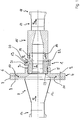
- the wort aeration device initially has, as shown in FIG. 1, a nozzle body 1.
- the nozzle body 1 is provided with a through opening which is circular in cross section and which forms the nozzle interior 2.
- the nozzle body 1 is provided with an external thread 3, onto which an annular cover 4, which has a corresponding internal thread 5, is screwed.
- the ring cover 4 has a radially outward-pointing flange region 6, to which in turn an outer flange 7 of an inflow connector 8 is flanged in a fluid-tight manner with a screw connection 9 which is only indicated schematically.
- the ring cover 4 has a protruding centering collar 10 which is encompassed by a corresponding recess 11 in the outer flange 7 of the inlet connection 8.
- the inlet connection 8 furthermore has a funnel region 12 which widens in the direction of flow, the smallest inside diameter of which essentially corresponds to the nominal diameter of the inflow line for the first fluid, ie. H. corresponds to the wort in this embodiment.
- the nominal diameter is usually in the range between 50 and 125 mm.
- the inlet connection 8 has fastening means in the form of a so-called milk pipe screw connection 13 for connecting a wort supply line, not shown.
- the nozzle body 1 in this exemplary embodiment has, in principle in the same way as in the area of its inflow end, an external thread 14 onto which an outflow connection 15, which is provided with a corresponding internal thread 16, is screwed.
- the outflow nozzle 15 narrows in the flow direction in the embodiment shown here and opens into a connection device 17 for connecting the discharge line for the aerated wort, which is not shown for reasons of clarity.
- the wort discharge line is connected in an analogous manner to the wort inlet through a milk pipe screw connection 18.
- the nozzle body 1 has a radial inflow opening 19, which essentially consists of a connecting piece 20 which has an internal thread 21 for connecting an air supply line, not shown.
- the inflow opening 19 opens radially on the inside into an annular gap 22 which surrounds the nozzle body 1 and opens towards the inlet end 23 of the nozzle body 1.
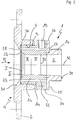
- FIG. 2 shows the core area of the device according to the invention shown by way of example, namely the nozzle body 1 and the ring cover 4, in an enlarged view.
- the nozzle body 1 consists of three nozzle body elements, namely an outer ring 1a, an inner ring 1b and a nozzle cover 1c.
- the outer ring 1a essentially has the shape of a pipe socket, which is provided in the region of its outlet end with a flange-like collar 24 which essentially surrounds the entire ring.
- the inner contour of the outer ring 1a is circular cylindrical.
- the outer ring 1a in the area of its flange-like collar 24, has the inflow opening 19 for the supply of sterile air for wort aeration.
- the inner ring 1b is arranged concentrically or coaxially with the outer ring 1a in the interior of the outer ring 1a.
- the inner ring 1b has a circular cylindrical outer contour, the outer diameter of the inner ring 1b being smaller than the inner diameter of the outer ring 1a. Due to this design, a is closed between the outer ring 1a and inner ring 1b, i.e. continuous circular annular gap 22 is formed, into which the inflow opening 19 opens.
- the inner contour of the inner ring 1b is profiled as described below.
- the nozzle cover 1c On the outlet side, the nozzle cover 1c is flange-mounted flush and fluid-tight on the outer ring 1a by means of a flange screw connection 25 which is only indicated schematically and consists of several screws.
- the nozzle cover 1c has a tubular socket-like shape with a flange-like circumferential shoulder 26, which is used for attachment to the outer ring 1a.
- the nozzle cover 1c is provided with an external thread 14 for fastening the outflow connection 15 shown in FIG. 1.
- the nozzle cover 1c is connected to the inner ring 1b or the inner ring 1b is fastened to the nozzle cover 1c via a screw connection 27, which is again only shown schematically, with screws arranged regularly on the circumference.
- the inner contour of the inner ring 1b and the inner contour of the nozzle cover 1c are matched to one another in such a way that the inner diameter of the inner ring 1b and the inner diameter of the nozzle cover 1c are the same in the region of their joint plane.
- Outer ring 1a, inner ring 1b and nozzle cover 1c are arranged concentrically or coaxially with one another.
- the annular gap 22 is closed in a fluidtight manner on the outlet end side by the nozzle cover 1c, so that the annular gap opens exclusively towards the inlet end side 23.
- the outer ring 1a has an external thread 3 on the inlet side, onto which the ring cover 4 is screwed with an internal thread 5 complementary thereto.
- the ring cover has a flange-like region 28 pointing radially inwards, which overlaps the annular gap 22 in the radial direction while leaving a small axial distance.
- An annular gap 29 is thereby formed.
- the axially outward, ie facing away from the nozzle body 1 surface 31 of the radially inward region 28 of the ring cover 4 widens funnel-like against the inflow direction shown by the arrow F1, with the opening angle of this funnel-like region, based on the Central axis is 32, 120 °. This enables a soft laminar entry of the wort to be aerated.
- the inner ring 1b has its smallest cross section 33 approximately in the region of the inflow opening. This corresponds to the nominal diameter here, i.e. the diameter of the wort supply line. From the inlet end, the cross section of the nozzle interior 2 narrows into four stages I, II, III and IV in the exemplary embodiment shown here. Each stage is designed in the shape of a truncated cone. The opening angle of stage I is 98 °, that of stage II 56 °, that of stage III 10 ° and that of stage IV is 1 °, in each case with respect to the central axis 32.
- the cross-section of the nozzle interior is expanded to the outlet-side end 34 of the nozzle cover 1c.
- This cross-sectional expansion is also frustoconical with an opening angle of 8 °.
- a laminar air flow initially surrounds the entire wort flow radially on the outside arises between the wort and the inner wall of the nozzle. Only in the area of the smallest cross-section does this laminar air flow increasingly detach from the inner wall of the nozzle and an intimate turbulent intermingling with the wort to be aerated.
Landscapes
- Chemical & Material Sciences (AREA)
- Chemical Kinetics & Catalysis (AREA)
- Nozzles (AREA)
- Distillation Of Fermentation Liquor, Processing Of Alcohols, Vinegar And Beer (AREA)
Applications Claiming Priority (2)
| Application Number | Priority Date | Filing Date | Title |
|---|---|---|---|
| DE4446000 | 1994-12-22 | ||
| DE4446000A DE4446000C2 (de) | 1994-12-22 | 1994-12-22 | Vorrichtung zum Mischen zweier strömender Fluide, insbesondere zum Belüften von Würze für die Bierherstellung |
Publications (1)
| Publication Number | Publication Date |
|---|---|
| EP0718032A1 true EP0718032A1 (fr) | 1996-06-26 |
Family
ID=6536733
Family Applications (1)
| Application Number | Title | Priority Date | Filing Date |
|---|---|---|---|
| EP95117905A Withdrawn EP0718032A1 (fr) | 1994-12-22 | 1995-11-14 | Dispositif pour mélanger deux fluides en mouvement, plus particulièrement pour l'aération de moût pour la préparation de bière |
Country Status (4)
| Country | Link |
|---|---|
| EP (1) | EP0718032A1 (fr) |
| CZ (1) | CZ343495A3 (fr) |
| DE (1) | DE4446000C2 (fr) |
| PL (1) | PL178359B1 (fr) |
Cited By (1)
| Publication number | Priority date | Publication date | Assignee | Title |
|---|---|---|---|---|
| WO2002000334A1 (fr) * | 2000-06-29 | 2002-01-03 | Statoil Asa | Procede de melange de fluides |
Citations (2)
| Publication number | Priority date | Publication date | Assignee | Title |
|---|---|---|---|---|
| DE9111657U1 (de) * | 1991-09-18 | 1991-11-14 | Anton Steinecker Entwicklungs-GmbH & Co., 8050 Freising | Belüftungsdüse für Flüssigkeiten |
| WO1992004972A1 (fr) * | 1990-09-21 | 1992-04-02 | Anton Steinecker Entwicklungs Gmbh & Co. | Buse d'aeration de liquides contenant des substances organiques |
-
1994
- 1994-12-22 DE DE4446000A patent/DE4446000C2/de not_active Expired - Fee Related
-
1995
- 1995-11-14 EP EP95117905A patent/EP0718032A1/fr not_active Withdrawn
- 1995-12-11 PL PL95311775A patent/PL178359B1/pl not_active IP Right Cessation
- 1995-12-21 CZ CZ953434A patent/CZ343495A3/cs unknown
Patent Citations (2)
| Publication number | Priority date | Publication date | Assignee | Title |
|---|---|---|---|---|
| WO1992004972A1 (fr) * | 1990-09-21 | 1992-04-02 | Anton Steinecker Entwicklungs Gmbh & Co. | Buse d'aeration de liquides contenant des substances organiques |
| DE9111657U1 (de) * | 1991-09-18 | 1991-11-14 | Anton Steinecker Entwicklungs-GmbH & Co., 8050 Freising | Belüftungsdüse für Flüssigkeiten |
Cited By (4)
| Publication number | Priority date | Publication date | Assignee | Title |
|---|---|---|---|---|
| WO2002000334A1 (fr) * | 2000-06-29 | 2002-01-03 | Statoil Asa | Procede de melange de fluides |
| AU2001269265B2 (en) * | 2000-06-29 | 2005-11-17 | Propure As | Method for mixing fluids |
| US7128276B2 (en) | 2000-06-29 | 2006-10-31 | Statoil Asa | Method for mixing fluids |
| CN1302838C (zh) * | 2000-06-29 | 2007-03-07 | 斯塔特石油公开有限公司 | 混合流体的方法 |
Also Published As
| Publication number | Publication date |
|---|---|
| DE4446000C2 (de) | 1997-11-20 |
| PL311775A1 (en) | 1996-06-24 |
| DE4446000A1 (de) | 1996-06-27 |
| CZ343495A3 (en) | 1996-07-17 |
| PL178359B1 (pl) | 2000-04-28 |
Similar Documents
| Publication | Publication Date | Title |
|---|---|---|
| EP2798987B1 (fr) | Procédé et dispositif de production de produits laitiers, notamment de mousse de lait | |
| EP0550510B1 (fr) | Buse d'aeration de liquides contenant des substances organiques | |
| EP2369231B1 (fr) | Dispositif de mélange pour un brûleur à gaz | |
| DE112012005017B4 (de) | Vorrichtung zum Steuern einer Fluid-Strömung in einem Notfall-Waschsystem, Vorrichtung zum Steuern einer Fluid-Strömung und Waschsystem zum Liefern einer Fluid-Strömung | |
| EP1296753A1 (fr) | Procede et dispositif pour reduire le nombre de produits secondaires lors du melange de courants d'eduit | |
| EP0533104B1 (fr) | Gicleur d'aération pour liquide | |
| EP0614693B1 (fr) | Gicleur d'aération pour aérer des liquides contenant des substances organiques | |
| EP2247373B1 (fr) | Procédé et utilisation d'un dispositif d'introduction d'air dans de l'eau | |
| EP0718043A1 (fr) | Installation de revêtement par poudrage | |
| EP3804861B1 (fr) | Buse d'injection pour un dispositif de pulvérisation et dispositif de pulvérisation | |
| WO2009086822A2 (fr) | Procédé et dispositif correspondant d'introduction sans pression ou essentiellement sans pression de mousse dans un flux de matériau sous pression | |
| DE4446000C2 (de) | Vorrichtung zum Mischen zweier strömender Fluide, insbesondere zum Belüften von Würze für die Bierherstellung | |
| DE9421971U1 (de) | Vorrichtung zum Mischen zweier strömender Fluide, insbesondere zum Belüften von Würze für die Bierherstellung | |
| EP0155683B1 (fr) | Procédé et dispositif de préparation de liquides pour arroser d'engrais les plantes à l'usage de ménages et des jardiniers amateurs | |
| DE4312994C2 (de) | Vorrichtung zur Verspritzung von Suspensionen, insbesondere Mörteln | |
| AT525247B1 (de) | Mischdüse zum Mischen einer Flüssigkeit mit Luft | |
| WO1990011877A1 (fr) | Convertisseur de jets de beton | |
| EP0264689B1 (fr) | Appareil producteur de mousse | |
| DE3520721C2 (fr) | ||
| DE202022104142U1 (de) | Vorrichtung zur Verwirbelung einer Flüssigkeit | |
| EP4309799A1 (fr) | Dispositif de tourbillonement d'un liquide | |
| DE20209039U1 (de) | Mischvorrichtung | |
| DE3418328A1 (de) | Vorrichtung zum belueften | |
| WO2018121970A1 (fr) | Mélangeur à fonctionnement continu pour fluides et procédé de fonctionement du mélangeur | |
| DE9209823U1 (de) | Vorrichtung zum Zumischen von Stoffen zu einem strömenden Medium |
Legal Events
| Date | Code | Title | Description |
|---|---|---|---|
| PUAI | Public reference made under article 153(3) epc to a published international application that has entered the european phase |
Free format text: ORIGINAL CODE: 0009012 |
|
| AK | Designated contracting states |
Kind code of ref document: A1 Designated state(s): AT BE CH DE ES FR GB LI NL |
|
| 17P | Request for examination filed |
Effective date: 19960620 |
|
| 17Q | First examination report despatched |
Effective date: 19980116 |
|
| GRAG | Despatch of communication of intention to grant |
Free format text: ORIGINAL CODE: EPIDOS AGRA |
|
| RTI1 | Title (correction) |
Free format text: DEVICE FOR AERATING WORT FOR THE BEER PRODUCTION |
|
| GRAG | Despatch of communication of intention to grant |
Free format text: ORIGINAL CODE: EPIDOS AGRA |
|
| GRAH | Despatch of communication of intention to grant a patent |
Free format text: ORIGINAL CODE: EPIDOS IGRA |
|
| STAA | Information on the status of an ep patent application or granted ep patent |
Free format text: STATUS: THE APPLICATION IS DEEMED TO BE WITHDRAWN |
|
| 18D | Application deemed to be withdrawn |
Effective date: 20010731 |