EP0718461A2 - Procédé et dispositif pour la pose d'un conduit dans un dispositif de type à sillon étagé - Google Patents
Procédé et dispositif pour la pose d'un conduit dans un dispositif de type à sillon étagé Download PDFInfo
- Publication number
- EP0718461A2 EP0718461A2 EP95118632A EP95118632A EP0718461A2 EP 0718461 A2 EP0718461 A2 EP 0718461A2 EP 95118632 A EP95118632 A EP 95118632A EP 95118632 A EP95118632 A EP 95118632A EP 0718461 A2 EP0718461 A2 EP 0718461A2
- Authority
- EP
- European Patent Office
- Prior art keywords
- shafts
- tube
- clearing
- trench
- heads
- Prior art date
- Legal status (The legal status is an assumption and is not a legal conclusion. Google has not performed a legal analysis and makes no representation as to the accuracy of the status listed.)
- Ceased
Links
- 238000000034 method Methods 0.000 title claims abstract description 10
- 238000005553 drilling Methods 0.000 claims abstract description 48
- 239000000725 suspension Substances 0.000 claims abstract description 30
- 230000005540 biological transmission Effects 0.000 claims abstract description 14
- 239000012530 fluid Substances 0.000 claims abstract description 12
- 238000009412 basement excavation Methods 0.000 claims abstract description 3
- 230000008878 coupling Effects 0.000 claims description 6
- 238000010168 coupling process Methods 0.000 claims description 6
- 238000005859 coupling reaction Methods 0.000 claims description 6
- 230000033001 locomotion Effects 0.000 claims description 4
- 239000002689 soil Substances 0.000 description 10
- 238000009434 installation Methods 0.000 description 4
- 239000000463 material Substances 0.000 description 4
- VNWKTOKETHGBQD-UHFFFAOYSA-N methane Chemical compound C VNWKTOKETHGBQD-UHFFFAOYSA-N 0.000 description 4
- 229910000831 Steel Inorganic materials 0.000 description 3
- -1 electricity Substances 0.000 description 3
- 239000010959 steel Substances 0.000 description 3
- 238000005520 cutting process Methods 0.000 description 2
- 230000000694 effects Effects 0.000 description 2
- 230000005611 electricity Effects 0.000 description 2
- 239000003345 natural gas Substances 0.000 description 2
- 239000002245 particle Substances 0.000 description 2
- 239000011435 rock Substances 0.000 description 2
- XLYOFNOQVPJJNP-UHFFFAOYSA-N water Substances O XLYOFNOQVPJJNP-UHFFFAOYSA-N 0.000 description 2
- 239000004698 Polyethylene Substances 0.000 description 1
- 239000004743 Polypropylene Substances 0.000 description 1
- 238000005299 abrasion Methods 0.000 description 1
- 229910000278 bentonite Inorganic materials 0.000 description 1
- 239000000440 bentonite Substances 0.000 description 1
- SVPXDRXYRYOSEX-UHFFFAOYSA-N bentoquatam Chemical compound O.O=[Si]=O.O=[Al]O[Al]=O SVPXDRXYRYOSEX-UHFFFAOYSA-N 0.000 description 1
- 238000005056 compaction Methods 0.000 description 1
- 230000006835 compression Effects 0.000 description 1
- 238000007906 compression Methods 0.000 description 1
- 238000009826 distribution Methods 0.000 description 1
- 239000003651 drinking water Substances 0.000 description 1
- 235000020188 drinking water Nutrition 0.000 description 1
- 238000010438 heat treatment Methods 0.000 description 1
- 238000012423 maintenance Methods 0.000 description 1
- 239000002184 metal Substances 0.000 description 1
- 238000005065 mining Methods 0.000 description 1
- 239000004033 plastic Substances 0.000 description 1
- 229920003023 plastic Polymers 0.000 description 1
- 229920000573 polyethylene Polymers 0.000 description 1
- 229920001155 polypropylene Polymers 0.000 description 1
- 238000003860 storage Methods 0.000 description 1
- 230000005641 tunneling Effects 0.000 description 1
- 238000003466 welding Methods 0.000 description 1
Images


Classifications
-
- E—FIXED CONSTRUCTIONS
- E21—EARTH OR ROCK DRILLING; MINING
- E21B—EARTH OR ROCK DRILLING; OBTAINING OIL, GAS, WATER, SOLUBLE OR MELTABLE MATERIALS OR A SLURRY OF MINERALS FROM WELLS
- E21B7/00—Special methods or apparatus for drilling
- E21B7/28—Enlarging drilled holes, e.g. by counterboring
-
- E—FIXED CONSTRUCTIONS
- E21—EARTH OR ROCK DRILLING; MINING
- E21B—EARTH OR ROCK DRILLING; OBTAINING OIL, GAS, WATER, SOLUBLE OR MELTABLE MATERIALS OR A SLURRY OF MINERALS FROM WELLS
- E21B10/00—Drill bits
- E21B10/44—Bits with helical conveying portion, e.g. screw type bits; Augers with leading portion or with detachable parts
-
- E—FIXED CONSTRUCTIONS
- E21—EARTH OR ROCK DRILLING; MINING
- E21B—EARTH OR ROCK DRILLING; OBTAINING OIL, GAS, WATER, SOLUBLE OR MELTABLE MATERIALS OR A SLURRY OF MINERALS FROM WELLS
- E21B10/00—Drill bits
- E21B10/60—Drill bits characterised by conduits or nozzles for drilling fluids
-
- E—FIXED CONSTRUCTIONS
- E21—EARTH OR ROCK DRILLING; MINING
- E21B—EARTH OR ROCK DRILLING; OBTAINING OIL, GAS, WATER, SOLUBLE OR MELTABLE MATERIALS OR A SLURRY OF MINERALS FROM WELLS
- E21B7/00—Special methods or apparatus for drilling
- E21B7/002—Drilling with diversely driven shafts extending into the borehole
Definitions
- the present invention relates to an apparatus and a method for laying cables in a trench-like arrangement.
- a device is used to create several holes in the ground arranged at different heights.
- the cables to be laid can be underground for long distances, i.e. Install without breaking the surface.
- the previously known underground installation systems each allow a single line to be pulled into the ground, but not the combined pulling of several lines in one operation.
- a lance is inserted into the ground through a small opening in the surface at an angle of 15 to 30 ° and, after reaching the intended laying depth, it is propelled horizontally up to 350 m away.
- a drilling suspension usually the environmentally friendly bentonite, emerges from the lance head at high pressure and provides the cutting forces required to loosen the soil. Furthermore, the drilling suspension partially discharges dissolved soil material, a targeted arrangement of the soil structure is achieved in the immediate driveway environment of the micro-tunnel, and the drilling is stabilized by the tixothropic behavior of the drilling suspension and the drilling wall is made slippery.
- the drilling lance After the drilling lance one up to 350 m away reached the excavated installation pit, the drilling lance is dismantled, a conical expansion head and the line to be laid are attached to the drill pipe and pulled into the bore in reverse.
- the expanding head used here extends the diameter of the bore to the desired nominal size up to 160 mm.
- Plastic pipes such as polyethylene or polypropylene pipes, but also steel pipes and socket pipes with sockets that cannot be removed under tensile load, are suitable as product pipes.
- the clearing heads can be set in rotation by a drive tube and a torque transmission arranged between them.
- the drive tube runs in a pull tube, which is firmly connected to the crossbar.
- the axes of the clearing heads can each be set in rotation by a hydraulic motor. This allows the draw tube as well as the crossbar to be dimensioned small, as a result of which those components which have to be moved through the ground offer less resistance and the force which is required when laying the lines is reduced.
- the device according to the invention By means of the device according to the invention, several, preferably two, clearers are set in rotation with the aid of a driven drive tube.
- the product pipes to be drawn in can be attached to the crossbar in alignment with the axes of the clearers, which are rotatably mounted on the crossbar.
- the advantageous method for creating step trenches is characterized by method claim 4. Accordingly, a drilling lance is driven to an equally deep assembly pit by means of a fully progressively controlled drilling method from an initial pit, which only has to be slightly deeper than the supply line to be laid deepest. After this pilot drilling, the step clearing device described in detail below is attached to the drill head or instead of the drilling head, and the step clearing device is moved backwards through the pilot hole from the assembly pit back to the starting pit.
- the product tubes with a maximum diameter of approximately 250 mm can already be attached to the crossbar.
- various exit points for a drilling suspension consist of special nozzles with the same or different passage sizes with an adjustable pressure between 20 and Emerge 400 bar. A significantly higher pressure can be selected for excavations in crumbly to medium-pressure-resistant rock.
- the step clearing device 10 shown in FIG. 1 does the pulling in of two product pipes of the same or different diameter in one work step.
- a drive tube 16 is rotatably guided in a draw tube 14.
- Both components, the draw tube 14 and the drive tube 16 consist of different detachable segments 14a, 14b, etc. or 16a, 16b, etc., which divide the draw tube 14 and the drive tube 16 into sections of approximately 3-5 meters in length.
- the various segments of the drive tube 16 can be connected to one another in a rotationally fixed manner, the various segments of the draw tube 14a, 14b, etc. are rigidly and detachably connected to one another both in the axial direction and in the direction of rotation.
- fastening options must be provided, as are known in the art for these purposes.
- the clearing heads 18 and 19 are rigidly connected to the clearing shafts 32, 33.
- the connection between the clearing heads 18, 19 and the clearing shafts 32, 33 can be done both by frictional engagement and by frictional engagement. However, due to the high forces and torques to be transmitted, a positive connection via a serration or a tension spring connection is preferable.
- a product pipe 38 or 39 can be attached to the crossbar 12 in alignment with the axes of the scraper shafts 32 and 33, respectively, and this in one operation by withdrawing the expansion and product pipe pull-in instrument 10 into the tubes in the ground generated by the clearing heads 18 and 19 to be confiscated.
- the product pipes 38 and 39 do not rotate.
- the clearing heads 18, 19 are driven via the drive tube 16 which is driven in the direction of rotation and which is rotatably mounted in the draw tube 14.
- the power transmission between drive tube 16 and the reamer shafts 32 and 33 can for example, by forming a cone gear head 26 on the drive tube 16.
- the conical gear head 26 is in meshing connection with bevel gears on two deflecting shafts 22, 23 along the transverse rod 12, so that the deflecting shafts are also set in rotational motion when the drive tube 16 is rotating.
- the deflection shafts 22 and 23 are rotatably fastened in the bearings 20 on the crossbar 12 and transmit the torque to the reamer shafts 32 and 33.
- bevel gears 40 are also provided between the deflection shafts 22 and 23 and the reamer axes 32 and 33, respectively. This form of torque transmission rotates the two reamer axes 32 and 33 in the opposite direction.
- Both the deflection shafts 22 and 23 as well as the reamer shafts 32 and 33 are rotatably mounted on the cross bar, both plain bearings and roller bearings being able to be used.
- Outlet openings 24 for drilling suspension are provided both on the clearing heads 18, 19 and at different positions of the cross bar 12.
- the drilling suspension fulfills various requirements: On the one hand, it should be under high pressure (20 - 400 bar) and thus provide cutting forces to loosen the soil; on the other hand, it should support the compaction work in the soil and help transport non-displaceable soil. Finally, it should make the drilling wall slippery and thus facilitate the pulling in of the product pipes.
- 1 shows only a small number of outlet openings 24 for drilling suspension, but in the preferred embodiment according to FIG. 1 there is a large number of these outlet openings 24 on the side of the crossbar 12 facing the clearing heads 18, 19 and on the clearing heads 18, 19 to provide. For example, depending on the diameter of the clearing head, there could be between 50 and 100 outlet openings 24 for drilling suspension on the clearing heads 18 and 19.
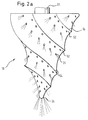
- the clearing head is made from a piece of a suitable metal, such as high-strength steel, and is rigidly connected to the clearing shaft.
- a suitable metal such as high-strength steel
- chisel pins 52 are attached to the clearing head and are made of an extremely hard material, preferably the material known under the name Widia.
- helical welding ribs 54 are applied to the clearing head, which are welded to the full material and represent a protection against abrasion.
- hard and abrasive particles e.g. Kurund particles, are involved.
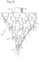
- FIG. 2b shows a further embodiment of a clearing head, in which the chisel pins 53 have a special shape which achieve a self-sharpening effect.
- Such self-sharpening Widia chisels are known from mining, where they are widely used in tunneling machines.
- the transmission of the torques from the drive tube 16 into the reamer shafts 32, 33 is realized via hydraulic couplings.
- a hydraulic clutch With a hydraulic clutch, the torque is transmitted via the dynamic effect of a circulating fluid.
- this form of torque transmission has the essential advantage that the drilling suspension, which is under very high pressure, can be used as hydraulic fluid.
- the drilling suspension is transported in the drive tube 16 designed as a hollow shaft, is guided via the hydraulic couplings into the deflection shafts 22, 23 designed as hollow shafts and finally reaches the tubular reamer shafts 32, 33 via the hydraulic couplings.
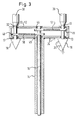
- FIG. 3 shows another embodiment of the present invention.
- the torques between the drive tube 16 and the reamer shafts 32, 33 are transmitted by toothed belts or chains 50.
- toothed disks or sprockets 44, 45 or 48, 49 are fixed in a rotationally fixed manner both on the drive tube 16 and on the reamer shafts 32 or 33, so that the belts or chains 50, 51 can transmit the required torques.
- a transmission shaft can be mounted next to one of the two reamer shafts 32 and 33 (not shown in FIG. 3), which reverses the direction of rotation of the relevant reamer shaft by being driven by the chain or the belt and is in contact with the scraper shaft through a toothing.
- Another possibility of reversing the direction of rotation is to provide a connection between the drive tube and the scraper shaft by means of a crosswise guidance of the belt or chain.
- FIG. 4 Another embodiment of the invention is shown in FIG. 4, in which all elements which have already been explained in more detail with reference to FIG. 1 are designated with the same reference numbers as in FIG. 1.
- the rotation of the clearing heads is achieved by the recoil of the drilling suspension emerging from the clearing heads 18, 19.
- the outlet openings 24 strike the circumferential surface of the clearing heads 18, 19 at an angle.
- Each drilling suspension jet emerging from an outlet opening 24 generates a recoil force, the The line of force does not run through the relevant axis of rotation of the reamer head 18, 19. A torque is thus generated which causes the clearing heads 18, 19 to rotate.
- all elements that serve to transmit the torques to the clearing heads in FIG. 1, such as a drive tube, deflection shafts and their storage and the interposed toothing, hydraulic couplings or chain or belt transmission, can be dispensed with.
- the drilling suspension is brought in via the draw tube 14 designed as a hollow shaft, running along or in the profile of the transverse rod 12 in a suitable flow channel (for example a steel tube 56) to the reamer axes 32, 33 and by means of a rotary leadthrough into the reamer axes 32, 33 designed as hollow shafts headed.
- This embodiment offers the advantage of being very simple and light and to allow a weaker design of the draw tube 14 because no drive tube has to be guided in it.
- the profile of the crossbar 12, which is also pulled through the ground, can be adapted to this task because the components for torque transmission do not have to be attached to the crossbar 12.
- drilling suspension likewise flows out under pressure through outlet openings 24 which are located on the crossbar, in particular on the front surface in the direction of pull. Since these outlet openings are not located on components that rotate during operation, any desired stationary transport of the drilling suspension, for example along the draw tube 14, can be provided and the drilling suspension to the outlet openings 24 attached to the crossbar 12 via a crossbar 12 in profile distribution system located.
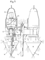
- the reamer shafts 32, 33 are driven by a hydraulic motor 70 through which a pressurized fluid flows. Oil, but also water, can be used as a possible drive fluid. Due to the separate drive of the individual reamer shafts, the device according to the present embodiment has a rigid draw tube 14 through which the drilling suspension and the drive fluid for the hydraulic motors are guided in separate flow channels 74, 72. The hydraulic fluid is delivered through pressure lines 72 to the hydraulic motors 70 which are driven by the hydraulic fluid.
- the hydraulic motors 70 are each rigidly connected to a reamer shaft 32, 33 and drive it.
- the drilling suspension is transmitted through the pressure line 74 on the one hand to the outlet openings 24 in the profile of the crossbar 12, on the other hand through a shaft bushing 76 into the reamer shafts 32, 33 and is transported from there to the outlet openings 24 on the clearing heads 18, 19.
- the transport of the drilling suspension and its transmission into the rotating reamer shafts can be achieved in various design variants, one of which is known to the person skilled in the art, one of which is shown in FIG. 5.
- the crossbar 12 can be brought into any angular position relative to the draw tube 14 and can be firmly fixed therein.
- the reamer shafts 32, 33 can also be inclined so that they can be aligned and fixed parallel to the draw tube 14.
- An angular attachment of the crossbar 12 reduces the spacing of the clearing shafts 32 and 33. This enables a different height level of the lines to be laid simultaneously to be produced using a single step clearing device 10 with a variable spacing of the clearing shafts 32, 33.
- the laying of lines in a trench-like arrangement proceeds in the following manner. Starting from an exit pit on the planned laying road, a pilot hole is drilled horizontally in the direction of an assembly pit that has also been created. The exact height of the pilot hole should take into account the geometry of the step clearing device used and the laying depth of the desired product pipes. After the drilling lance has reached the assembly pit, the drill pipe is pulled back to the starting pit and, depending on the geometry of the holding bar used, the bore diameter is enlarged with an expanding head. During the pulling back of the drill pipe, sections of the draw tube and at the same time sections of the drive tube are introduced into the area of the pilot bore and are connected to one another. The length of the above sections is preferably about 3-5 meters. After the drill pipe with the expanding head has been pulled back to the exit pit and at the same time the draw tube and drive tube have reached the exit pit, the step clearing device 10 is fastened to the draw tube and the drive tube in the assembly pit.
- the drive tube In the exit pit, the drive tube is connected to a drive unit, not shown in the drawings, and the draw tube is held by a device, also not shown in the drawings.
- the drilling suspension is fed into the step clearing device under high pressure, the drive tube is rotated and the draw tube is pulled towards the exit pit, whereby the sections of the draw tube and the drive tube emerging from the former pilot hole are released again.
- product pipes which also consist of individual sections, can be gradually attached to the product pipes entering the bores.
- the step clearing device After the step clearing device has reached the exit pit and the product pipes have reached the exit pit, the product pipes are connected to one another in the assembly pit and the assembly pit is refilled with soil.
- a new exit pit will be excavated at a distance of up to 350 meters from the previous exit pit and the previous exit pit will now be used as an assembly pit, in which the step clearing device and the sections of the draw tube and the drive tube are already located, so that the above explained Operations can be carried out again.
Landscapes
- Engineering & Computer Science (AREA)
- Life Sciences & Earth Sciences (AREA)
- Geology (AREA)
- Mining & Mineral Resources (AREA)
- Physics & Mathematics (AREA)
- Environmental & Geological Engineering (AREA)
- Fluid Mechanics (AREA)
- General Life Sciences & Earth Sciences (AREA)
- Geochemistry & Mineralogy (AREA)
- Mechanical Engineering (AREA)
- Excavating Of Shafts Or Tunnels (AREA)
- Earth Drilling (AREA)
Applications Claiming Priority (4)
| Application Number | Priority Date | Filing Date | Title |
|---|---|---|---|
| DE4445301 | 1994-12-19 | ||
| DE4445301 | 1994-12-19 | ||
| DE19523769A DE19523769C1 (de) | 1994-12-19 | 1995-06-29 | Vorrichtung und Verfahren zur Leitungsverlegung in stufengrabenartiger Anordnung |
| DE19523769 | 1995-06-29 |
Publications (2)
| Publication Number | Publication Date |
|---|---|
| EP0718461A2 true EP0718461A2 (fr) | 1996-06-26 |
| EP0718461A3 EP0718461A3 (fr) | 1998-04-29 |
Family
ID=25943022
Family Applications (1)
| Application Number | Title | Priority Date | Filing Date |
|---|---|---|---|
| EP95118632A Ceased EP0718461A3 (fr) | 1994-12-19 | 1995-11-27 | Procédé et dispositif pour la pose d'un conduit dans un dispositif de type à sillon étagé |
Country Status (1)
| Country | Link |
|---|---|
| EP (1) | EP0718461A3 (fr) |
Cited By (1)
| Publication number | Priority date | Publication date | Assignee | Title |
|---|---|---|---|---|
| CN111877987A (zh) * | 2020-08-12 | 2020-11-03 | 中油昆仑管道工程有限公司 | 套管安装组件 |
Family Cites Families (2)
| Publication number | Priority date | Publication date | Assignee | Title |
|---|---|---|---|---|
| DD260407A3 (de) * | 1986-06-17 | 1988-09-28 | Sdag Wismut | Automatische vorschubkraftregelung beim gesteinsbohren in abhaengigkeit der gesteinsfestigkeit |
| DE4134095C1 (fr) * | 1991-10-15 | 1992-07-16 | Flowtex Technologie Import Von Kabelverlegemaschinen Gmbh, 7505 Ettlingen, De |
-
1995
- 1995-11-27 EP EP95118632A patent/EP0718461A3/fr not_active Ceased
Non-Patent Citations (1)
| Title |
|---|
| None |
Cited By (1)
| Publication number | Priority date | Publication date | Assignee | Title |
|---|---|---|---|---|
| CN111877987A (zh) * | 2020-08-12 | 2020-11-03 | 中油昆仑管道工程有限公司 | 套管安装组件 |
Also Published As
| Publication number | Publication date |
|---|---|
| EP0718461A3 (fr) | 1998-04-29 |
Similar Documents
| Publication | Publication Date | Title |
|---|---|---|
| EP0798443B1 (fr) | Procédé de forage directionnel | |
| EP2553202B1 (fr) | Procédé pour faire fonctionner un dispositif de forage horizontal et dispositif de forage horizontal | |
| EP0365612B1 (fr) | Perforatrice | |
| EP0190669B1 (fr) | Dispositif de forage | |
| EP3441207A1 (fr) | Procédé de carottage et dispositifs de mise en oeuvre dudit procédé | |
| EP0953723B1 (fr) | Dispositif d'élargissement | |
| DE102018133369A1 (de) | Bohrvorrichtung und Bohrverfahren | |
| EP2728104A1 (fr) | Procédé de réalisation d'un forage horizontal dans le sol et dispositif de forage horizontal | |
| EP0548588B1 (fr) | Dispositif pour réaliser des forages dans le sol | |
| WO2018121815A1 (fr) | Dispositif de forage | |
| DE1909931B2 (de) | Vorrichtung zum ueberlagerungsbohren | |
| EP2553203B1 (fr) | Dispositif de forage horizontal | |
| EP0522446A2 (fr) | Procédé pour contrôler la direction d'un appareil de forage du sol et dispositif pour l'exécution de forages | |
| CH704416A2 (de) | Bohranlage zum Durchführen von Bohrungen im Erdreich. | |
| DE102011014912A1 (de) | Maschinelle Vorrichtung zur Erstellung bergmännischer Hohlräume | |
| DE102016003749B4 (de) | Bohranlage zum Einbringen von Bohrungen in Gestein und/oder Felsen | |
| EP2423388A1 (fr) | Procédé et dispositif de fabrication d'une paroi moulée | |
| DE19523769C1 (de) | Vorrichtung und Verfahren zur Leitungsverlegung in stufengrabenartiger Anordnung | |
| DE10325576B4 (de) | Führungskopf zum Erdbohren und Erdbohrmaschine | |
| DE19946587A1 (de) | Vorrichtung zum Richtungsbohren | |
| DE4006320C1 (en) | Straight line tunnel borer - has guide tube to which casing is connected with load-out conveyor | |
| DE3326303C2 (de) | Vorrichtung zum Herstellen verrohrter Bohrungen | |
| DE2817017C2 (de) | Horizontalpreßbohrgerät | |
| EP4146900A1 (fr) | Turbine de forage et procédé de forage directionnel | |
| DE19549160C1 (de) | Bohrvorrichtung |
Legal Events
| Date | Code | Title | Description |
|---|---|---|---|
| PUAI | Public reference made under article 153(3) epc to a published international application that has entered the european phase |
Free format text: ORIGINAL CODE: 0009012 |
|
| AK | Designated contracting states |
Kind code of ref document: A2 Designated state(s): AT CH ES FR IT LI NL |
|
| PUAL | Search report despatched |
Free format text: ORIGINAL CODE: 0009013 |
|
| AK | Designated contracting states |
Kind code of ref document: A3 Designated state(s): AT CH ES FR IT LI NL |
|
| 17P | Request for examination filed |
Effective date: 19980525 |
|
| RAP1 | Party data changed (applicant data changed or rights of an application transferred) |
Owner name: FLOWTEX TECHNOLOGIE GMBH & CO. KG |
|
| GRAG | Despatch of communication of intention to grant |
Free format text: ORIGINAL CODE: EPIDOS AGRA |
|
| 17Q | First examination report despatched |
Effective date: 20000302 |
|
| STAA | Information on the status of an ep patent application or granted ep patent |
Free format text: STATUS: THE APPLICATION HAS BEEN REFUSED |
|
| 18R | Application refused |
Effective date: 20000819 |