EP0718472A1 - Verfahren zur Krafterzeugung mittels einer Gasturbine, die verbrannte, befeuchtete Luft verwendet - Google Patents
Verfahren zur Krafterzeugung mittels einer Gasturbine, die verbrannte, befeuchtete Luft verwendet Download PDFInfo
- Publication number
- EP0718472A1 EP0718472A1 EP95308945A EP95308945A EP0718472A1 EP 0718472 A1 EP0718472 A1 EP 0718472A1 EP 95308945 A EP95308945 A EP 95308945A EP 95308945 A EP95308945 A EP 95308945A EP 0718472 A1 EP0718472 A1 EP 0718472A1
- Authority
- EP
- European Patent Office
- Prior art keywords
- air
- stream
- water
- humidified
- recovery unit
- Prior art date
- Legal status (The legal status is an assumption and is not a legal conclusion. Google has not performed a legal analysis and makes no representation as to the accuracy of the status listed.)
- Withdrawn
Links
Images


Classifications
-
- F—MECHANICAL ENGINEERING; LIGHTING; HEATING; WEAPONS; BLASTING
- F01—MACHINES OR ENGINES IN GENERAL; ENGINE PLANTS IN GENERAL; STEAM ENGINES
- F01K—STEAM ENGINE PLANTS; STEAM ACCUMULATORS; ENGINE PLANTS NOT OTHERWISE PROVIDED FOR; ENGINES USING SPECIAL WORKING FLUIDS OR CYCLES
- F01K21/00—Steam engine plants not otherwise provided for
- F01K21/04—Steam engine plants not otherwise provided for using mixtures of steam and gas; Plants generating or heating steam by bringing water or steam into direct contact with hot gas
- F01K21/047—Steam engine plants not otherwise provided for using mixtures of steam and gas; Plants generating or heating steam by bringing water or steam into direct contact with hot gas having at least one combustion gas turbine
-
- F—MECHANICAL ENGINEERING; LIGHTING; HEATING; WEAPONS; BLASTING
- F02—COMBUSTION ENGINES; HOT-GAS OR COMBUSTION-PRODUCT ENGINE PLANTS
- F02C—GAS-TURBINE PLANTS; AIR INTAKES FOR JET-PROPULSION PLANTS; CONTROLLING FUEL SUPPLY IN AIR-BREATHING JET-PROPULSION PLANTS
- F02C3/00—Gas-turbine plants characterised by the use of combustion products as the working fluid
- F02C3/20—Gas-turbine plants characterised by the use of combustion products as the working fluid using a special fuel, oxidant, or dilution fluid to generate the combustion products
- F02C3/30—Adding water, steam or other fluids for influencing combustion, e.g. to obtain cleaner exhaust gases
- F02C3/305—Increasing the power, speed, torque or efficiency of a gas turbine or the thrust of a turbojet engine by injecting or adding water, steam or other fluids
-
- F—MECHANICAL ENGINEERING; LIGHTING; HEATING; WEAPONS; BLASTING
- F05—INDEXING SCHEMES RELATING TO ENGINES OR PUMPS IN VARIOUS SUBCLASSES OF CLASSES F01-F04
- F05D—INDEXING SCHEME FOR ASPECTS RELATING TO NON-POSITIVE-DISPLACEMENT MACHINES OR ENGINES, GAS-TURBINES OR JET-PROPULSION PLANTS
- F05D2260/00—Function
- F05D2260/20—Heat transfer, e.g. cooling
- F05D2260/211—Heat transfer, e.g. cooling by intercooling, e.g. during a compression cycle
-
- F—MECHANICAL ENGINEERING; LIGHTING; HEATING; WEAPONS; BLASTING
- F05—INDEXING SCHEMES RELATING TO ENGINES OR PUMPS IN VARIOUS SUBCLASSES OF CLASSES F01-F04
- F05D—INDEXING SCHEME FOR ASPECTS RELATING TO NON-POSITIVE-DISPLACEMENT MACHINES OR ENGINES, GAS-TURBINES OR JET-PROPULSION PLANTS
- F05D2260/00—Function
- F05D2260/20—Heat transfer, e.g. cooling
- F05D2260/212—Heat transfer, e.g. cooling by water injection
Definitions
- This invention pertains to a process for producing mechanical power by utilizing compressed humidified air and a fuel to produce hot combustion gas for expansion in a gas turbine. It pertains particularly to such a power process in which hot compressed air is humidified with heated water and further heated in a heat recovery unit provided upstream of a fuel combustor and hot gas turbine.
- the present invention provides an improved gas turbine power producing process which utilizes compressed air which is humidified and further heated and mixed with fuel in a combustor, and the hot combustion gas expanded in a gas turbine.
- the air is first compressed and intercooled, and the air is further compressed and heated in a combined saturator and heat recovery unit, in which the air is mixed with heated water stream to achieve saturation before feeding the hot saturated air with a fuel to a combustor.
- the hot water is usually spray mixed into the hot compressed air stream, and the temperature of the water spray mixing point can be varied as desired to achieve maximum thermal efficiency.
- the resulting pressurized hot combustion gas is then expanded through a gas turbine to produce mechanical power, and the hot expanded gas is passed back through the heat recovery unit to heat the humidified air and saturating water, after which the cooled exhaust gas is discharged through an exhaust stack to the atmosphere.
- This invention advantageously provides a power producing process having increased thermal efficiency and reduced investment costs. Because this new power producing process does not utilize a compressor aftercooler and separate saturator unit with its associated water circulation system for the compressed air, the compressed air heating and humidification steps are combined, the overall thermal efficiency for the process is increased. Also, the capital cost for process equipment is correspondingly reduced.
- the humidified air at 23 is mixed with a fuel and combusted in combustor 24 and expanded in gas turbine 26, with the resulting hot exhaust gas 27 from gas turbine 26 being passed through the heat recovery unit 22, where heat from the exhaust gas is used to heat the air stream 23 to the fuel combustor 24.
- a water recycle system provides for the water circulation to the saturator 20 ⁇ and remove additional heat from the gas turbine exhaust gas in recovery unit 22.
- this known power process utilizes a separate aftercooler 18 and separator saturator 20 ⁇ for providing the humidified air at 21 upstream of the heat recovery unit 22.
- the improved power process design modifies and improves the known humidified air gas turbine cycle.
- air supply at 30 ⁇ is compressed in low pressure compressor unit 32 to 70 ⁇ -80 ⁇ psia pressure and 40 ⁇ 0 ⁇ -420 ⁇ °F temperature, and the compressed air at 33 then cooled at intercooler 34 to about 10 ⁇ 0 ⁇ °F against a water stream provided at 35.
- the cooled air is further compressed in high pressure compressor unit 36 to 30 ⁇ 0 ⁇ -330 ⁇ psia and 450 ⁇ -460 ⁇ °F, after which the hot compressed air at 38 is passed directly to heat recovery unit 40 ⁇ , where it is mixed and humidified with water stream 37 from the intercooler 34.
- Such mixing of the compressed air and water streams is provided by a spray nozzle 42 by which the pressurized water stream 41 is sprayed into pressurized air stream 43.
- the spray nozzle 42 may be located external to the heat recovery unit 40 ⁇ , it is preferably located within the heat recovery unit 40 ⁇ for improved thermal efficiency.
- the resulting compressed and humidified air stream at 43 is further heated to 850 ⁇ -950 ⁇ °F against hot gas turbine exhaust gas flowing in passageway 51.
- An additional water stream is provided at 39 as needed to supplement the cooling water stream 37 and provide desired humidification of the air stream 43.
- the resulting compressed and humidified air at 44 is at 850 ⁇ -950 ⁇ °F temperature and is fed together with a fuel provided at 45, such as natural gas or oil, to combustor 46 for producing a hot combustion gas at 47.
- a fuel provided at 45, such as natural gas or oil
- the supplemental water stream 39 and amount of humidification of the compressed air stream 38 is controlled so that the temperature of the hot combustion gas at 47 does not exceed about 20 ⁇ 0 ⁇ 0 ⁇ °F.
- This hot combustion gas at 47 is expanded through gas turbine 48 to produce mechanical power for driving the two staged air compressor units 32 and 36, which power may also be used to drive an electric power generator 50 ⁇ .
- hot exhaust gas at 49 having 950 ⁇ -110 ⁇ 0 ⁇ °F temperature is passed back through the heat recovery unit 40 ⁇ in passageway 51 to heat both the compressed air-water stream 43 and the saturating water streams 37 and 39 in the passageway 41.
- the cooled exhaust gas at 52 at about 250 ⁇ °F temperature is then discharged through a stack (not shown) to the atmosphere.
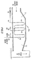
- the heat recovery unit 40 ⁇ will usually be provided with a horizontal thermally-insulated casing 40 ⁇ a containing a plurality of vertically-oriented finned tubes through which the water stream at 41 and the compressed air-water mixture at 43 are passed, as shown in more detail by Fig. 3.
- the water stream in passageway 41 is injected into passageway 43 by spray nozzle 42.
- the hot turbine exhaust gas stream is passed through the casing passageway 51 to heat the water streams 41 and air-water stream 43, after which the cooled turbine exhaust gas is passed through passageway 52 to the stack 54.
- the known power process per Fig. 1 utilizes a multi-stage saturator unit to humidify the compressed air, in which unit the water is evaporated at relatively low temperatures.
- the present design process per Fig. 2 uses an integral air-water mixing and water evaporation step, in which the water boiling temperature increases during the air humidification step. This varying temperature evaporation of the saturating water is thermodynamically superior to the generally constant temperature boiling step utilized by the prior art by reducing the lost work, which difference can be understood from reference to a temperature-entropy (T-S) diagram.
- T-S temperature-entropy
- the high pressure compressor unit 36 does not require or utilize an aftercooler or a saturator unit, together with their associated water circulating system. Instead, the compressed hot air stream at 38 is fed directly to the saturator and heat recovery unit 40 ⁇ , where the compressed air is mixed with heated water in passageway 41 at the spray nozzle 42.
- the water stream 37 which is preheated at the intercooler 34 together with make-up water at 39 is further heated in heat recovery unit 40 ⁇ , after which it is mixed with the compressed hot air stream 38.
- the two-phase air-water mixture passes through the heat recovery unit 40 ⁇ , where the water is evaporated and the air-vapor mixture is superheated.
- the location of the spray nozzle 42 can be varied relative to passageways 41 and 43 to achieve the most favorable temperature pattern and highest thermodynamic efficiency.
- the resulting hot compressed and humidified air stream at 44 is mixed with a fuel 45 which is burned in the combustor 46.
- the compressed humidified air at 44 serves to limit the combustion gas temperature from the combustor 46 to not exceeding about 20 ⁇ 0 ⁇ 0 ⁇ °F.
- the present power process design per Fig. 2 provides significant advantages compared with the known humidified air gas turbine power processes. Because this new design process does not require an aftercooler and saturator units and the water circulating system, capital cost for the process equipment is reduced. Also, as the known process uses circulation water as the heat carrying agent, three driving forces of temperature are required: (1) heat transfer between the hot exhaust gas and recycle water at the heat recovery unit, (2) exit water to inlet air at the saturator, and (3) hot water to exit humidified air at the saturator.
- the present process design does not need consideration of these temperature driving forces, as the water is directly fed to the heat recovery unit 40 ⁇ , so that the air humidification and heating therein is thermodynamically more efficient, and the exhaust gas temperature at stack 54 can be advantageously reduced to a lower level. For this reason, less heat is rejected from the present process and the overall thermal efficiency of the process is correspondingly and desirably increased.
- Fig. 1 is a simplified temperature-heat transfer (T-Q) diagram in which lower line 60 ⁇ represents the two-phase air-water stream 43 being heated by hot turbine exhaust gas stream represented by line upper 62.
- the minimum differential temperature ( ⁇ T) pinch point occurs at a higher temperature and is smaller than that for the known power cycle per Fig. 1. For these reasons, the thermal efficiency of the present process is further increased.
- the present design power process desirably provides an unexpected higher thermal efficiency and lower capital costs.
- air is first compressed to an intermediate pressure and intercooled against a water stream.
- the cooled air is then further compressed and passed directly to a heat recovery unit, where it is humidified using the water stream from the intercooling step.
- the compressed humidified air is further heated against gas turbine hot exhaust gas, then mixed with natural gas fuel and combusted.
- the resulting hot combustion gas is expanded through the gas turbine to produce mechanical power, and the turbine hot exhaust gas is cooled against the compressed humidified air and water streams before the exhaust gas is discharged to atmosphere.
- Important characteristics of the present power producing process are as follows: First Stage Compression Air discharge pressure, psia 170 ⁇ Air discharge temperature, °F 40 ⁇ 0 ⁇ Air intercooled temperature, °F 10 ⁇ 0 ⁇ Water temp. after intercooler, °F 90 ⁇ Second Stage Compression Air discharge pressure, psig 330 ⁇ Air discharge temp., °F 460 ⁇ Heat Recovery Unit Water inlet temp., °F 90 ⁇ Air-water mixing temp., °F 410 ⁇ -420 ⁇ Air temp. to combustion unit, °F 90 ⁇ 0 ⁇ Gas temp. to turbine, °F 1,90 ⁇ 0 ⁇ Turbine exhaust gas pressure, psia 50 ⁇ Turbine exhaust gas temp., °F 1,0 ⁇ 0 ⁇ 0 ⁇ Exhaust gas temp. to atmosphere, °F 250 ⁇
Landscapes
- Engineering & Computer Science (AREA)
- Chemical & Material Sciences (AREA)
- Combustion & Propulsion (AREA)
- Mechanical Engineering (AREA)
- General Engineering & Computer Science (AREA)
- Engine Equipment That Uses Special Cycles (AREA)
Applications Claiming Priority (2)
| Application Number | Priority Date | Filing Date | Title |
|---|---|---|---|
| US359270 | 1994-12-19 | ||
| US08/359,270 US5513488A (en) | 1994-12-19 | 1994-12-19 | Power process utilizing humidified combusted air to gas turbine |
Publications (1)
| Publication Number | Publication Date |
|---|---|
| EP0718472A1 true EP0718472A1 (de) | 1996-06-26 |
Family
ID=23413096
Family Applications (1)
| Application Number | Title | Priority Date | Filing Date |
|---|---|---|---|
| EP95308945A Withdrawn EP0718472A1 (de) | 1994-12-19 | 1995-12-08 | Verfahren zur Krafterzeugung mittels einer Gasturbine, die verbrannte, befeuchtete Luft verwendet |
Country Status (6)
| Country | Link |
|---|---|
| US (1) | US5513488A (de) |
| EP (1) | EP0718472A1 (de) |
| JP (1) | JPH08232684A (de) |
| CN (1) | CN1129768A (de) |
| AU (1) | AU4050395A (de) |
| CA (1) | CA2165280A1 (de) |
Cited By (1)
| Publication number | Priority date | Publication date | Assignee | Title |
|---|---|---|---|---|
| EP0959235A2 (de) | 1998-05-20 | 1999-11-24 | Hitachi, Ltd. | Gasturbinenkraftwerk |
Families Citing this family (38)
| Publication number | Priority date | Publication date | Assignee | Title |
|---|---|---|---|---|
| US20040244382A1 (en) * | 1992-10-27 | 2004-12-09 | Hagen David L. | Distributed direct fluid contactor |
| US6564556B2 (en) | 1992-10-27 | 2003-05-20 | J. Lyell Ginter | High efficiency low pollution hybrid brayton cycle combustor |
| USRE43252E1 (en) | 1992-10-27 | 2012-03-20 | Vast Power Portfolio, Llc | High efficiency low pollution hybrid Brayton cycle combustor |
| DE19651645C2 (de) * | 1996-12-12 | 2002-10-24 | Deutsch Zentr Luft & Raumfahrt | Verfahren zur Nutzung von Solarenergie in einem Gas- und Dampf-Kraftwerk und Gas- und Dampf-Kraftwerk |
| JP3786759B2 (ja) * | 1997-06-26 | 2006-06-14 | エア・ウォーター株式会社 | ガス発生装置 |
| US5778675A (en) * | 1997-06-20 | 1998-07-14 | Electric Power Research Institute, Inc. | Method of power generation and load management with hybrid mode of operation of a combustion turbine derivative power plant |
| US6038849A (en) | 1998-07-07 | 2000-03-21 | Michael Nakhamkin | Method of operating a combustion turbine power plant using supplemental compressed air |
| DE19837251C1 (de) * | 1998-08-17 | 2000-02-10 | Siemens Ag | Gas- und Dampfturbinenanlage |
| CN1237261C (zh) * | 1998-10-23 | 2006-01-18 | 株式会社日立制作所 | 燃气轮机发电设备及空气加湿器 |
| JP4099944B2 (ja) * | 1998-10-23 | 2008-06-11 | 株式会社日立製作所 | ガスタービン発電設備及び空気増湿装置 |
| AU2172500A (en) | 1998-12-11 | 2000-06-26 | Allied-Signal Inc. | Power generation system, and heat exchanger and operating method for a power generation system |
| US6363706B1 (en) * | 1998-12-24 | 2002-04-02 | Alliedsignal | Apparatus and method to increase turbine power |
| US6223519B1 (en) | 1999-02-11 | 2001-05-01 | Bp Amoco Corporation | Method of generating power using an advanced thermal recuperation cycle |
| US6526758B2 (en) | 2000-05-12 | 2003-03-04 | General Electric Company | Method and apparatus for power augmentation for gas turbine power cycles |
| US6530224B1 (en) | 2001-03-28 | 2003-03-11 | General Electric Company | Gas turbine compressor inlet pressurization system and method for power augmentation |
| US6499303B1 (en) | 2001-04-18 | 2002-12-31 | General Electric Company | Method and system for gas turbine power augmentation |
| DE50206291D1 (de) | 2001-07-13 | 2006-05-18 | Alstom Technology Ltd | Gasturbinenanlage sowie ein zugehöriges Betriebsverfahren |
| JP4179496B2 (ja) * | 2002-10-08 | 2008-11-12 | 川崎重工業株式会社 | 常圧燃焼タービンシステム |
| US8631657B2 (en) * | 2003-01-22 | 2014-01-21 | Vast Power Portfolio, Llc | Thermodynamic cycles with thermal diluent |
| JP4377818B2 (ja) * | 2003-03-18 | 2009-12-02 | フルー・コーポレイシヨン | 二酸化炭素を回収することを備える湿り空気タービンサイクル |
| US7637093B2 (en) * | 2003-03-18 | 2009-12-29 | Fluor Technologies Corporation | Humid air turbine cycle with carbon dioxide recovery |
| EP1609958A1 (de) * | 2004-06-22 | 2005-12-28 | Siemens Aktiengesellschaft | Gasturbine mit einem Verdichter und einem Rekuperator |
| EP1795725B1 (de) * | 2005-10-12 | 2011-01-19 | Alstom Technology Ltd | Gasturbine mit geregelter Luftkühlung |
| JP4343188B2 (ja) * | 2006-05-26 | 2009-10-14 | 株式会社日立製作所 | 高湿分ガスタービン設備 |
| CN101622054B (zh) * | 2007-01-25 | 2012-12-05 | 国际壳牌研究有限公司 | 减少发电装置中二氧化碳排放的方法 |
| JP4120699B2 (ja) * | 2007-07-06 | 2008-07-16 | 株式会社日立製作所 | ガスタービン発電設備及び空気増湿装置 |
| EP2067940B2 (de) * | 2007-09-07 | 2023-02-15 | General Electric Technology GmbH | Verfahren zum Betrieb eines Kombikraftwerks sowie Kombikraftwerk zur Durchführung des Verfahrens |
| US8220268B2 (en) * | 2007-11-28 | 2012-07-17 | Caterpillar Inc. | Turbine engine having fuel-cooled air intercooling |
| US8833079B2 (en) * | 2008-09-18 | 2014-09-16 | Douglas W. P. Smith | Method and apparatus for generating electricity |
| US8327641B2 (en) * | 2009-12-01 | 2012-12-11 | General Electric Company | System for generation of power using solar energy |
| CN103061887A (zh) * | 2013-01-11 | 2013-04-24 | 中国兵器工业集团第七0研究所 | 一种中冷燃气轮机 |
| CN103775208B (zh) * | 2013-01-19 | 2016-08-24 | 摩尔动力(北京)技术股份有限公司 | 增湿热力循环系统 |
| CN104196629A (zh) * | 2014-09-04 | 2014-12-10 | 山西潞安矿业(集团)有限责任公司 | 燃料气增焓湿化装置 |
| US10215060B2 (en) * | 2014-11-06 | 2019-02-26 | Powerphase Llc | Gas turbine efficiency and power augmentation improvements utilizing heated compressed air |
| JP6407079B2 (ja) * | 2015-03-25 | 2018-10-17 | 三菱日立パワーシステムズ株式会社 | 高湿分空気利用ガスタービンシステム及びその排ガス処理システム |
| CN106948942B (zh) * | 2017-04-24 | 2018-07-06 | 石家庄新华能源环保科技股份有限公司 | 一种高效燃气轮机 |
| CN107448249A (zh) * | 2017-07-14 | 2017-12-08 | 中国神华能源股份有限公司 | 燃机透平冷却控制方法及装置、存储介质 |
| CN119122671A (zh) * | 2024-10-09 | 2024-12-13 | 南京航空航天大学 | 一种基于露点蒸发冷却的湿化燃气轮机系统 |
Citations (8)
| Publication number | Priority date | Publication date | Assignee | Title |
|---|---|---|---|---|
| EP0051487A1 (de) * | 1980-11-04 | 1982-05-12 | Mitsubishi Gas Chemical Company, Inc. | Wärmetauschsystem für eine Wärmemaschine, die einen gasartigen komprimierten Brennstoff verwendet |
| EP0051493A2 (de) * | 1980-11-05 | 1982-05-12 | Mitsubishi Gas Chemical Company, Inc. | Wärmeübertragungssystem für einen offenen Kreislauf einer inneren Verbrennung |
| US4829763A (en) | 1984-02-01 | 1989-05-16 | Fluor Corporation | Process for producing power |
| EP0353374A1 (de) * | 1988-07-25 | 1990-02-07 | Abb Stal Ab | Gasturbinenanlage für kombinierte Erzeugung von Elektro- und Wärmeenergie und seine Betriebsweise |
| US5160096A (en) | 1991-10-11 | 1992-11-03 | United Technologies Corporation | Gas turbine cycle |
| US5181376A (en) | 1990-08-10 | 1993-01-26 | Fluor Corporation | Process and system for producing power |
| US5201796A (en) | 1991-10-15 | 1993-04-13 | United Technologies Corporation | Gas turbine engine arrangement |
| US5218815A (en) | 1991-06-04 | 1993-06-15 | Donlee Technologies, Inc. | Method and apparatus for gas turbine operation using solid fuel |
Family Cites Families (9)
| Publication number | Priority date | Publication date | Assignee | Title |
|---|---|---|---|---|
| US3657879A (en) * | 1970-01-26 | 1972-04-25 | Walter J Ewbank | Gas-steam engine |
| US3788066A (en) * | 1970-05-05 | 1974-01-29 | Brayton Cycle Improvement Ass | Refrigerated intake brayton cycle system |
| DE3275652D1 (en) * | 1981-12-10 | 1987-04-16 | Mitsubishi Gas Chemical Co | Regenerative gas turbine cycle |
| JPS6335881A (ja) * | 1986-07-30 | 1988-02-16 | 昭和電工株式会社 | 吸水性繊維の製造方法 |
| EP0439754B1 (de) * | 1990-01-31 | 1995-07-26 | Asea Brown Boveri Ag | Verfahren zum Anfahren einer Kombianlage |
| JPH0472048A (ja) * | 1990-07-10 | 1992-03-06 | Nippon Steel Corp | 溶接性に優れた合金化溶融亜鉛めっき鋼板 |
| JPH0587651A (ja) * | 1991-05-14 | 1993-04-06 | Atsugi Unisia Corp | 荷重検出装置 |
| EP0589960B1 (de) * | 1991-06-17 | 1997-01-02 | Electric Power Research Institute, Inc | Energieanlage mit komprimiertem luftspeicher |
| JPH061056A (ja) * | 1992-06-22 | 1994-01-11 | Toyobo Co Ltd | フレキソ印刷方法 |
-
1994
- 1994-12-19 US US08/359,270 patent/US5513488A/en not_active Expired - Fee Related
-
1995
- 1995-12-08 EP EP95308945A patent/EP0718472A1/de not_active Withdrawn
- 1995-12-14 CA CA002165280A patent/CA2165280A1/en not_active Abandoned
- 1995-12-15 JP JP7327096A patent/JPH08232684A/ja active Pending
- 1995-12-18 AU AU40503/95A patent/AU4050395A/en not_active Abandoned
- 1995-12-19 CN CN95120499.8A patent/CN1129768A/zh active Pending
Patent Citations (8)
| Publication number | Priority date | Publication date | Assignee | Title |
|---|---|---|---|---|
| EP0051487A1 (de) * | 1980-11-04 | 1982-05-12 | Mitsubishi Gas Chemical Company, Inc. | Wärmetauschsystem für eine Wärmemaschine, die einen gasartigen komprimierten Brennstoff verwendet |
| EP0051493A2 (de) * | 1980-11-05 | 1982-05-12 | Mitsubishi Gas Chemical Company, Inc. | Wärmeübertragungssystem für einen offenen Kreislauf einer inneren Verbrennung |
| US4829763A (en) | 1984-02-01 | 1989-05-16 | Fluor Corporation | Process for producing power |
| EP0353374A1 (de) * | 1988-07-25 | 1990-02-07 | Abb Stal Ab | Gasturbinenanlage für kombinierte Erzeugung von Elektro- und Wärmeenergie und seine Betriebsweise |
| US5181376A (en) | 1990-08-10 | 1993-01-26 | Fluor Corporation | Process and system for producing power |
| US5218815A (en) | 1991-06-04 | 1993-06-15 | Donlee Technologies, Inc. | Method and apparatus for gas turbine operation using solid fuel |
| US5160096A (en) | 1991-10-11 | 1992-11-03 | United Technologies Corporation | Gas turbine cycle |
| US5201796A (en) | 1991-10-15 | 1993-04-13 | United Technologies Corporation | Gas turbine engine arrangement |
Non-Patent Citations (1)
| Title |
|---|
| J.MAKANSI: "Gas turbines grab wider share of power generation duties", POWER, vol. 134, no. 3, NEW YORK US, pages 40 - 44, XP000116492 * |
Cited By (3)
| Publication number | Priority date | Publication date | Assignee | Title |
|---|---|---|---|---|
| EP0959235A2 (de) | 1998-05-20 | 1999-11-24 | Hitachi, Ltd. | Gasturbinenkraftwerk |
| US6247302B1 (en) | 1998-05-20 | 2001-06-19 | Hitachi, Ltd. | Gas turbine power plant |
| US6397578B2 (en) | 1998-05-20 | 2002-06-04 | Hitachi, Ltd. | Gas turbine power plant |
Also Published As
| Publication number | Publication date |
|---|---|
| US5513488A (en) | 1996-05-07 |
| CN1129768A (zh) | 1996-08-28 |
| CA2165280A1 (en) | 1996-06-20 |
| AU4050395A (en) | 1996-06-27 |
| JPH08232684A (ja) | 1996-09-10 |
Similar Documents
| Publication | Publication Date | Title |
|---|---|---|
| EP0718472A1 (de) | Verfahren zur Krafterzeugung mittels einer Gasturbine, die verbrannte, befeuchtete Luft verwendet | |
| US5331806A (en) | Hydrogen fuelled gas turbine | |
| US4829763A (en) | Process for producing power | |
| US4271665A (en) | Installation for generating pressure gas or mechanical energy | |
| US5406786A (en) | Integrated air separation - gas turbine electrical generation process | |
| CN1069379C (zh) | 空气蓄积器式涡轮机 | |
| EP0150990B1 (de) | Verfahren zur Leistungsproduktion | |
| US5181376A (en) | Process and system for producing power | |
| US6263661B1 (en) | System for power generation | |
| US6684643B2 (en) | Process for the operation of a gas turbine plant | |
| US4785621A (en) | Air bottoming cycle for coal gasification plant | |
| US7516609B2 (en) | Carbon dioxide recirculation | |
| US5313782A (en) | Combined gas/steam power station plant | |
| US4841721A (en) | Very high efficiency hybrid steam/gas turbine power plant wiht bottoming vapor rankine cycle | |
| US20050028529A1 (en) | Method of generating energy in a power plant comprising a gas turbine, and power plant for carrying out the method | |
| WO1995011375A3 (en) | Performance enhanced gas turbine powerplants | |
| EP0444913A1 (de) | Gasturbine | |
| JPH08510311A (ja) | 中間冷却と復熱を用いた高能率多軸再熱タービン | |
| JPH11510581A (ja) | 水素燃料半密閉蒸気タービン発電プラント | |
| EP0607232B1 (de) | Gasturbinenkreislauf | |
| CA2207448A1 (en) | Recuperative steam cooled gas turbine | |
| CA2263036C (en) | Gas turbine combined cycle | |
| US6499300B2 (en) | Method for operating a power plant | |
| US6199363B1 (en) | Method for operating a gas turbogenerator set | |
| US5337554A (en) | Method for reducing the pressure of a gas from a primary network |
Legal Events
| Date | Code | Title | Description |
|---|---|---|---|
| PUAI | Public reference made under article 153(3) epc to a published international application that has entered the european phase |
Free format text: ORIGINAL CODE: 0009012 |
|
| AK | Designated contracting states |
Kind code of ref document: A1 Designated state(s): DE ES FR GB IT SE |
|
| 17P | Request for examination filed |
Effective date: 19961227 |
|
| 17Q | First examination report despatched |
Effective date: 19971229 |
|
| STAA | Information on the status of an ep patent application or granted ep patent |
Free format text: STATUS: THE APPLICATION IS DEEMED TO BE WITHDRAWN |
|
| 18D | Application deemed to be withdrawn |
Effective date: 19980709 |