EP0718478A1 - Abgasbehandlungsvorrichtung einer Dieselbrennkraftmaschine mit einem Katalysator und einem Stickoxydenadsorber, die in Abgaskrümmer angeordnet sind - Google Patents
Abgasbehandlungsvorrichtung einer Dieselbrennkraftmaschine mit einem Katalysator und einem Stickoxydenadsorber, die in Abgaskrümmer angeordnet sind Download PDFInfo
- Publication number
- EP0718478A1 EP0718478A1 EP95402671A EP95402671A EP0718478A1 EP 0718478 A1 EP0718478 A1 EP 0718478A1 EP 95402671 A EP95402671 A EP 95402671A EP 95402671 A EP95402671 A EP 95402671A EP 0718478 A1 EP0718478 A1 EP 0718478A1
- Authority
- EP
- European Patent Office
- Prior art keywords
- casing
- manifold
- exhaust
- catalyst body
- adsorption
- Prior art date
- Legal status (The legal status is an assumption and is not a legal conclusion. Google has not performed a legal analysis and makes no representation as to the accuracy of the status listed.)
- Granted
Links
Images




Classifications
-
- B—PERFORMING OPERATIONS; TRANSPORTING
- B01—PHYSICAL OR CHEMICAL PROCESSES OR APPARATUS IN GENERAL
- B01D—SEPARATION
- B01D53/00—Separation of gases or vapours; Recovering vapours of volatile solvents from gases; Chemical or biological purification of waste gases, e.g. engine exhaust gases, smoke, fumes, flue gases, aerosols
- B01D53/34—Chemical or biological purification of waste gases
- B01D53/92—Chemical or biological purification of waste gases of engine exhaust gases
- B01D53/94—Chemical or biological purification of waste gases of engine exhaust gases by catalytic processes
- B01D53/9481—Catalyst preceded by an adsorption device without catalytic function for temporary storage of contaminants, e.g. during cold start
-
- F—MECHANICAL ENGINEERING; LIGHTING; HEATING; WEAPONS; BLASTING
- F01—MACHINES OR ENGINES IN GENERAL; ENGINE PLANTS IN GENERAL; STEAM ENGINES
- F01N—GAS-FLOW SILENCERS OR EXHAUST APPARATUS FOR MACHINES OR ENGINES IN GENERAL; GAS-FLOW SILENCERS OR EXHAUST APPARATUS FOR INTERNAL-COMBUSTION ENGINES
- F01N13/00—Exhaust or silencing apparatus characterised by constructional features
- F01N13/009—Exhaust or silencing apparatus characterised by constructional features having two or more separate purifying devices arranged in series
-
- F—MECHANICAL ENGINEERING; LIGHTING; HEATING; WEAPONS; BLASTING
- F01—MACHINES OR ENGINES IN GENERAL; ENGINE PLANTS IN GENERAL; STEAM ENGINES
- F01N—GAS-FLOW SILENCERS OR EXHAUST APPARATUS FOR MACHINES OR ENGINES IN GENERAL; GAS-FLOW SILENCERS OR EXHAUST APPARATUS FOR INTERNAL-COMBUSTION ENGINES
- F01N13/00—Exhaust or silencing apparatus characterised by constructional features
- F01N13/011—Exhaust or silencing apparatus characterised by constructional features having two or more purifying devices arranged in parallel
-
- F—MECHANICAL ENGINEERING; LIGHTING; HEATING; WEAPONS; BLASTING
- F01—MACHINES OR ENGINES IN GENERAL; ENGINE PLANTS IN GENERAL; STEAM ENGINES
- F01N—GAS-FLOW SILENCERS OR EXHAUST APPARATUS FOR MACHINES OR ENGINES IN GENERAL; GAS-FLOW SILENCERS OR EXHAUST APPARATUS FOR INTERNAL-COMBUSTION ENGINES
- F01N3/00—Exhaust or silencing apparatus having means for purifying, rendering innocuous, or otherwise treating exhaust
- F01N3/08—Exhaust or silencing apparatus having means for purifying, rendering innocuous, or otherwise treating exhaust for rendering innocuous
- F01N3/0807—Exhaust or silencing apparatus having means for purifying, rendering innocuous, or otherwise treating exhaust for rendering innocuous by using absorbents or adsorbents
- F01N3/0814—Exhaust or silencing apparatus having means for purifying, rendering innocuous, or otherwise treating exhaust for rendering innocuous by using absorbents or adsorbents combined with catalytic converters, e.g. NOx absorption/storage reduction catalysts
-
- F—MECHANICAL ENGINEERING; LIGHTING; HEATING; WEAPONS; BLASTING
- F01—MACHINES OR ENGINES IN GENERAL; ENGINE PLANTS IN GENERAL; STEAM ENGINES
- F01N—GAS-FLOW SILENCERS OR EXHAUST APPARATUS FOR MACHINES OR ENGINES IN GENERAL; GAS-FLOW SILENCERS OR EXHAUST APPARATUS FOR INTERNAL-COMBUSTION ENGINES
- F01N3/00—Exhaust or silencing apparatus having means for purifying, rendering innocuous, or otherwise treating exhaust
- F01N3/08—Exhaust or silencing apparatus having means for purifying, rendering innocuous, or otherwise treating exhaust for rendering innocuous
- F01N3/0807—Exhaust or silencing apparatus having means for purifying, rendering innocuous, or otherwise treating exhaust for rendering innocuous by using absorbents or adsorbents
- F01N3/0828—Exhaust or silencing apparatus having means for purifying, rendering innocuous, or otherwise treating exhaust for rendering innocuous by using absorbents or adsorbents characterised by the absorbed or adsorbed substances
- F01N3/0842—Nitrogen oxides
-
- F—MECHANICAL ENGINEERING; LIGHTING; HEATING; WEAPONS; BLASTING
- F01—MACHINES OR ENGINES IN GENERAL; ENGINE PLANTS IN GENERAL; STEAM ENGINES
- F01N—GAS-FLOW SILENCERS OR EXHAUST APPARATUS FOR MACHINES OR ENGINES IN GENERAL; GAS-FLOW SILENCERS OR EXHAUST APPARATUS FOR INTERNAL-COMBUSTION ENGINES
- F01N2250/00—Combinations of different methods of purification
- F01N2250/12—Combinations of different methods of purification absorption or adsorption, and catalytic conversion
-
- F—MECHANICAL ENGINEERING; LIGHTING; HEATING; WEAPONS; BLASTING
- F01—MACHINES OR ENGINES IN GENERAL; ENGINE PLANTS IN GENERAL; STEAM ENGINES
- F01N—GAS-FLOW SILENCERS OR EXHAUST APPARATUS FOR MACHINES OR ENGINES IN GENERAL; GAS-FLOW SILENCERS OR EXHAUST APPARATUS FOR INTERNAL-COMBUSTION ENGINES
- F01N2330/00—Structure of catalyst support or particle filter
- F01N2330/08—Granular material
-
- F—MECHANICAL ENGINEERING; LIGHTING; HEATING; WEAPONS; BLASTING
- F01—MACHINES OR ENGINES IN GENERAL; ENGINE PLANTS IN GENERAL; STEAM ENGINES
- F01N—GAS-FLOW SILENCERS OR EXHAUST APPARATUS FOR MACHINES OR ENGINES IN GENERAL; GAS-FLOW SILENCERS OR EXHAUST APPARATUS FOR INTERNAL-COMBUSTION ENGINES
- F01N2330/00—Structure of catalyst support or particle filter
- F01N2330/10—Fibrous material, e.g. mineral or metallic wool
-
- F—MECHANICAL ENGINEERING; LIGHTING; HEATING; WEAPONS; BLASTING
- F01—MACHINES OR ENGINES IN GENERAL; ENGINE PLANTS IN GENERAL; STEAM ENGINES
- F01N—GAS-FLOW SILENCERS OR EXHAUST APPARATUS FOR MACHINES OR ENGINES IN GENERAL; GAS-FLOW SILENCERS OR EXHAUST APPARATUS FOR INTERNAL-COMBUSTION ENGINES
- F01N2470/00—Structure or shape of exhaust gas passages, pipes or tubes
- F01N2470/12—Tubes being corrugated
-
- F—MECHANICAL ENGINEERING; LIGHTING; HEATING; WEAPONS; BLASTING
- F01—MACHINES OR ENGINES IN GENERAL; ENGINE PLANTS IN GENERAL; STEAM ENGINES
- F01N—GAS-FLOW SILENCERS OR EXHAUST APPARATUS FOR MACHINES OR ENGINES IN GENERAL; GAS-FLOW SILENCERS OR EXHAUST APPARATUS FOR INTERNAL-COMBUSTION ENGINES
- F01N2470/00—Structure or shape of exhaust gas passages, pipes or tubes
- F01N2470/14—Plurality of outlet tubes, e.g. in parallel or with different length
-
- F—MECHANICAL ENGINEERING; LIGHTING; HEATING; WEAPONS; BLASTING
- F01—MACHINES OR ENGINES IN GENERAL; ENGINE PLANTS IN GENERAL; STEAM ENGINES
- F01N—GAS-FLOW SILENCERS OR EXHAUST APPARATUS FOR MACHINES OR ENGINES IN GENERAL; GAS-FLOW SILENCERS OR EXHAUST APPARATUS FOR INTERNAL-COMBUSTION ENGINES
- F01N2470/00—Structure or shape of exhaust gas passages, pipes or tubes
- F01N2470/18—Structure or shape of exhaust gas passages, pipes or tubes the axis of inlet or outlet tubes being other than the longitudinal axis of apparatus
-
- F—MECHANICAL ENGINEERING; LIGHTING; HEATING; WEAPONS; BLASTING
- F01—MACHINES OR ENGINES IN GENERAL; ENGINE PLANTS IN GENERAL; STEAM ENGINES
- F01N—GAS-FLOW SILENCERS OR EXHAUST APPARATUS FOR MACHINES OR ENGINES IN GENERAL; GAS-FLOW SILENCERS OR EXHAUST APPARATUS FOR INTERNAL-COMBUSTION ENGINES
- F01N2470/00—Structure or shape of exhaust gas passages, pipes or tubes
- F01N2470/24—Concentric tubes or tubes being concentric to housing, e.g. telescopically assembled
-
- F—MECHANICAL ENGINEERING; LIGHTING; HEATING; WEAPONS; BLASTING
- F02—COMBUSTION ENGINES; HOT-GAS OR COMBUSTION-PRODUCT ENGINE PLANTS
- F02B—INTERNAL-COMBUSTION PISTON ENGINES; COMBUSTION ENGINES IN GENERAL
- F02B3/00—Engines characterised by air compression and subsequent fuel addition
- F02B3/06—Engines characterised by air compression and subsequent fuel addition with compression ignition
-
- Y—GENERAL TAGGING OF NEW TECHNOLOGICAL DEVELOPMENTS; GENERAL TAGGING OF CROSS-SECTIONAL TECHNOLOGIES SPANNING OVER SEVERAL SECTIONS OF THE IPC; TECHNICAL SUBJECTS COVERED BY FORMER USPC CROSS-REFERENCE ART COLLECTIONS [XRACs] AND DIGESTS
- Y02—TECHNOLOGIES OR APPLICATIONS FOR MITIGATION OR ADAPTATION AGAINST CLIMATE CHANGE
- Y02C—CAPTURE, STORAGE, SEQUESTRATION OR DISPOSAL OF GREENHOUSE GASES [GHG]
- Y02C20/00—Capture or disposal of greenhouse gases
- Y02C20/10—Capture or disposal of greenhouse gases of nitrous oxide (N2O)
Definitions
- the invention relates to a device for treating the exhaust gas of a compression-ignition engine of a motor vehicle in order to achieve the most complete possible elimination of the nitrogen oxides contained in the exhaust gas.
- the exhaust gases from compression-ignition or diesel engines contain various pollutants, the discharge into the atmosphere of which must be minimized. These pollutants consist mainly of carbon monoxide CO, unburnt hydrocarbons HC, nitrogen oxides NO x and soot particles.
- Nitrogen oxides reduction catalysts or Denox catalysts which are active in carrying out the reduction of nitrogen oxides in exhaust gases, in temperature ranges between 200 and 350 ° C or between 350 and 600 ° C. Within these ranges, the conversion rate of nitrogen oxides by reduction can be represented by conversion peaks, the maximum of which can reach up to 50% of nitrogen oxides converted into nitrogen N 2 and oxygen O 2 and which are centered on temperatures of 250 and 400 to 450 ° C, respectively, depending on the type of catalyst used.
- the catalysts ensuring the conversion of nitrogen oxides between 200 and 350 ° C with a conversion peak centered on 250 ° C can be constituted by precious metals on oxide supports, such as platinum or palladium deposited on a body. alumina or titanium oxide or perovskites.
- Denox catalysts operating between 350 and 600 ° C with a conversion peak centered on a temperature between 400 and 450 ° C can consist of hydrothermally stable zeolites (for example Cu-ZSM5).
- Diesel engine approval tests with regard to the discharge of pollutants, are defined so that the exhaust gas temperatures are between 80 and 220 ° C with an average of about 150 ° C, during the first part of the official certification cycle defined by the standards European and between 200 and 450 or even 550 ° C in the case of certain atmospheric engines, with an average temperature centered between 250 and 280 ° C, during a second part of the certification cycle.
- the treatment device comprising a trap for nitrogen oxides can function correctly insofar as the desorption of nitrogen oxides occurs at a time when the main reduction catalyst Denox is at a temperature at which it exhibits effective activity .
- the trap It is therefore necessary for the trap to absorb nitrogen oxides during the entire first phase of the certification cycle and until the Denox catalyst has reached a sufficient temperature during the second hot part of the certification cycle, the trap thus ensuring the desorption of the trapped nitrogen oxides which come into contact with the Denox catalyst, the temperature of which is sufficient to ensure its initiation.
- the catalyst can then convert nitrogen oxides to nitrogen and oxygen.
- the trap In order to obtain maximum efficiency from the treatment device, it is preferable for the trap to absorb nitrogen oxides at ambient temperature and ensure their desorption within the conversion temperature range of the main Denox catalyst.
- Treatment devices have been proposed in which the nitrogen oxide adsorber is placed in different ways relative to the main catalyst Denox.
- Internal combustion engines such as diesel engines may include an exhaust manifold having a cylindrical casing into which open, in a substantially tangential direction, the exhaust pipes of each of the engine cylinders.
- At least one of the longitudinal ends of the exhaust manifold is connected to an exhaust line of the motor vehicle.
- the object of the invention is therefore to propose a device for treating the exhaust gases of a compression-ignition engine of a motor vehicle comprising at least one catalyst body disposed inside an exhaust manifold. of the engine having a cylindrical casing into which opens, in a substantially tangential direction, at least one exhaust manifold connected to a cylinder of the engine and which is connected, at at least one of its longitudinal ends, to at least an exhaust line of the motor vehicle, this processing device making it possible to carry out the conversion of the nitrogen oxides contained in the exhaust gases discharged in any phase of the vehicle operating or approval cycle.
- the treatment device comprises, inside the cylindrical envelope of the exhaust manifold, the catalyst body in a central arrangement and at least one means for adsorption of nitrogen oxides from the exhaust gas in a peripheral arrangement around the catalyst body, so that the exhaust gas introduced by the tubing into the casing circulates in a swirl around the catalyst body in contact with the adsorption means and with a surface external of the catalyst body.
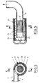
- Figures 1 and 2 relate to a first embodiment of the invention.
- FIG. 1 is a view in axial section along 1-1 of FIG. 2.
- Figure 2 is a cross-sectional view along 2-2 of Figure 1.
- Figures 3 and 4 relate to a second embodiment of a device according to the invention.
- FIG. 3 is a view in axial section along 3-3 of FIG. 4.
- Figure 4 is a cross-sectional view along 4-4 of Figure 3.
- Figures 5 and 6 relate to a third embodiment of the processing device according to the invention.
- FIG. 5 is a view in longitudinal section along 5-5 of FIG. 6.
- FIG. 6 is a cross-sectional view along 6-6 of FIG. 5.
- Figure 7 is a top view of a diesel engine equipped with a processing device according to the invention.
- FIG. 8 is a sectional view along 8-8 of FIG. 7.
- Figure 9 is a top view in section of a diesel engine comprising a processing device according to the invention and according to an alternative embodiment.
- Figure 10 is a sectional view along 10-10 of Figure 9.
- FIGS. 1 and 2 we can see an exhaust gas treatment device according to the invention generally designated by the reference 1, arranged at inside the exhaust manifold 2 of a diesel engine.
- the exhaust manifold 2 comprises a casing 3 made of stainless steel sheet, of substantially cylindrical shape closed at one of its ends by a slightly curved bottom 4, so as to form inside the casing 3, a cavity 4a of substantially toroidal shape.
- the rectilinear terminal section 8 of the exhaust line constituting an exhaust gas collection conduit inside the manifold extends in the axial direction 7, inside the casing 3 of the manifold, on a length slightly less than the total length of the manifold, so that the end of the conduit 8 is opposite and close to the bottom 4 of the casing 3 in which the cavity 4a is formed.
- the casing 3 of the manifold 2 has an opening in its upper part, at the level of which is fixed by welding, on the casing 3, a tube 9 comprising a flange 9a for connection to the Diesel engine cylinder head.
- the tubing 9 opens inside the casing 3 of the manifold 2 in a direction 9b substantially tangential to the cylindrical casing 3.
- the exhaust gases from the diesel engine which circulate in the direction of the axis 9b of the tubing, as indicated by arrow 10, penetrate in a tangential direction inside the envelope 3 and are circulated inside the envelope 3, in the form of a rotary current around the axis 7 of the envelope 3 of the collector, as shown by the arrows 11.
- the exhaust gas treatment device generally designated by the reference numeral 1, which is disposed entirely inside the casing 3 of the manifold, comprises a catalyst body 12 disposed inside the duct 8, in its part introduced inside the collector and an adsorber 14 disposed around the catalyst body 12 and the duct 8, in an annular space delimited inside the casing 3 of the manifold by the duct 8.
- the catalyst body 12 which can be fixed inside a metallic cylindrical casing 13 inserted in the duct 8, comprises a support traversed by gas circulation channels of longitudinal direction substantially parallel to the axis 7 of the collector casing on which catalyst materials such as precious metals are deposited.
- the catalyst body 12 produced in monolithic form must allow both the conversion by oxidation of carbon monoxide CO and HC hydrocarbons in the form of carbon dioxide CO 2 and water vapor H 2 O and the conversion of the oxides of l nitrogen NO x by reduction, in the form of nitrogen N 2 and oxygen O 2 .
- the catalyst body 12 is of the type designated by the name oxidant-Denox.
- Such a catalyst body is an element known in the art of building catalytic converters.
- the nitrogen oxide adsorber 14 can be produced in the form of a tubular casing 15 of corrugated stainless steel sheet coated with a nitrogen oxide adsorber such as for example a slightly substituted zirconium oxide with manganese, such as Zr 0.9 Mn 0.1 O 2 .
- the tubular casing 15 can be produced by winding on itself a corrugated sheet of stainless steel coated with nitrogen oxide adsorption material or directly in the form of a stainless steel tube coated externally and internally with adsorption material and having, along its periphery, successive corrugations of axial direction.
- the tubular casing 15 of the adsorber 14 has a length in the axial direction substantially equal to the distance between the flat bottom 5 and the peripheral part of the domed bottom 4 of the manifold 2.
- the tubular casing 15 of the adsorber 14 can be fixed inside the envelope 3, by clamping between the bottoms 5 and 6 of the collector.
- the tubular casing 15 of the adsorber 14 is pierced by through openings 16 distributed over its entire surface, so as to allow the exhaust gases entering the collector, to pass through the casing of the adsorber which is thus permeable exhaust fumes over its entire surface.
- the exhaust gases penetrating in a tangential direction into the casing 3 of the manifold come into contact with the casing 15 of the adsorber 14 which is coated with a layer of material for adsorption of nitrogen oxides.
- the openings 16 allow the passage of gases inside the envelope 15, so that the exhaust gas in swirling circulation around the axis 7 of the manifold chamber 3, as shown by the arrows 11, can come into contact with the casing 15 on its outer face and on its inner face and with the outer surface of the exhaust duct 8 in which the catalyst body 12 is disposed.
- the hot gases coming from the engine and in vortex circulation therefore come in contact with the adsorber 14 and are in thermal contact with the external surface of the catalyst body 12 which they heat up.
- the active surface of the envelope 15 is increased by the presence of the corrugations.
- the corrugations promote contact of the exhaust gases with the active surfaces by disturbing their flow.
- the nitrogen oxides contained in the exhaust gases are adsorbed by the surfaces of the adsorber 14 in a significant proportion.
- the adsorption materials are chosen so that the nitrogen oxides are adsorbed at room temperature. The adsorption of nitrogen oxides is therefore carried out from the start of the diesel engine and during all the initial phases of engine operation during which the exhaust gases are at a relatively low temperature, for example below 200 ° C.
- the adsorber 14 in particular ensures the adsorption of large quantities of nitrogen oxides from the exhaust gases, throughout the cold part of the homologation cycle.
- the exhaust gases come into contact with the exterior surface of the exhaust duct 8 in which the catalyst body 12 is arranged.
- the exhaust gases therefore heat the catalyst body 12, the exterior surface of which is in intimate contact with the inner surface of the duct 8.
- the temperature of the catalyst body 12 rises gradually, due to its being brought into thermal contact with the exhaust gases, the temperature of which increases.
- the exhaust gases pass through the catalyst body 12, without any conversion of the nitrogen oxides in nitrogen and oxygen.
- the constituent elements of the treatment device namely the catalyst body 12 and the adsorber 14 are produced in such a way that the adsorber 14 reaches its desorption temperature for nitrogen oxides, substantially at the moment when the catalyst body 12 reaches its initiation temperature for reduction of nitrogen oxides.
- the nitrogen oxides retained in the trap constituted by the adsorber 14 are gradually released and penetrate with the exhaust gases which carry out their sweeping, inside the exhaust duct 8 in which is the catalyst body 12.
- the catalyst body 12 which is at a temperature at least equal to its initiation temperature for the reduction of nitrogen oxides ensures the conversion of nitrogen oxides to nitrogen and oxygen, in a proportion important.
- the gases released to the atmosphere contain only small amounts of nitrogen oxides.
- the nitrogen oxides contained in the exhaust gases are adsorbed by the adsorber 14, during the first part of the cycle, the exhaust gases being at a temperature below the desorption temperature.
- the exhaust gases and the catalyst body 12 are still at a temperature below the starting temperature of the nitrogen oxide conversion catalyst, and the desorption temperature. nitrogen oxides of the adsorber 14 is not yet reached.
- the catalyst initiation temperature and the desorption temperature are reached practically simultaneously during the second part of the approval cycle.
- the gaseous releases of nitrogen oxides may be limited to a value below standards, during the first part and during the start of the second part of the approval cycle, due to the adsorption of nitrogen oxides by l adsorber 14.
- the treatment device according to the invention therefore makes it possible to limit the discharge of nitrogen oxides in all the operating phases of the diesel engine and to meet the most demanding standards.
- FIGS. 3 and 4 and in FIGS. 5 and 6 a second and a third embodiment of a treatment device according to the invention are shown. arranged inside an exhaust manifold of a diesel engine.
- the second and third embodiments of the treatment device according to the invention differ from the first embodiment only in the structure and the mounting of the adsorber. This part of the device will therefore only be described opposite Figures 3 and 4 and opposite Figures 5 and 6, respectively.
- the adsorption means 20 consists of a layer of metal fibers 19 coated with nitrogen oxide adsorption material held against the interior surface of the chamber cylindrical 3 of the manifold 2 by an annular piece 21 of metal mesh made from stainless steel wires.
- the annular piece 21 of metal mesh is threaded onto the end part of the exhaust duct 8 and has a thickness in the radial direction allowing it to hold the layer 19 of metal fibers coated with adsorption material by elastic clamping against the inner surface of the casing 3 of the collector 2.
- the layer of fibers 19 has an annular shape and has a through opening at the opening of the casing 3 along which the tubing 9 is fixed.
- the operation of the device shown in Figures 3 and 4 is substantially identical to the operation of the device shown in Figures 1 and 2, the exhaust gases entering the exhaust manifold coming into contact with the layer 19 of metal fibers coated with adsorbent material, during their vortex circulation around the axis of the chamber of the collector.
- the exhaust gases come into contact with the exterior surface of the exhaust duct 8 through the mesh 21 and ensures the heating of the catalyst body 12 through the wall of the exhaust duct 8.
- Figures 5 and 6 show a third embodiment of a processing device according to the invention.
- the nitrogen oxide adsorber 22 consists of a bed of alumina beads 23 coated with a material for adsorption of nitrogen oxides held against the inner wall of the cylindrical chamber 3 of the exhaust manifold 2 by a cylindrical casing 24 made of stainless steel sheet placed and fixed in a coaxial arrangement inside the chamber of the cylindrical casing 3 of the manifold 2.
- the tubular casing 24 made of stainless steel is crossed by openings 25 whose diameter is slightly less than the diameter of the balls constituting the bed 23.
- the alumina balls of the bed 23 have a diameter which can range from 2 to 3 mm.
- the bed 23 fills an annular space between the inner wall of the casing 3 of the collector and the wall of the stainless steel casing 24 arranged coaxially with respect to the casing 3.
- the bed of balls 23 is interrupted at the level the opening of the tube 9 opening into the manifold chamber 2.
- the bed of balls 23 could be held against the internal surface of the casing 3 by an annular piece of wire mesh of stainless steel wires similar to the annular piece 21 shown in FIGS. 3 and 4, engaged on the duct 8 constituting an envelope containing the catalyst body 12.
- the exhaust gases introduced into the manifold chamber 2 through the tube 9 enter the bed balls 23 of the adsorber 22 and circulate, inside the bed of balls, in contact with the external surface of the balls which is coated with a material for adsorption of nitrogen oxides. Part of the nitrogen oxides contained in the exhaust gases is retained by the adsorber 22 as soon as the engine is started, the exhaust gases being at a temperature close to ambient temperature.
- the exhaust gases passing through the openings 25 enter the annular space between the stainless steel casing 24 holding the ball bed 23 and the exhaust duct 8 in which the catalyst body 12 is disposed.
- the exhaust gases which are in vortex circulation around the axis of the manifold within this space gradually heat the catalyst body 12 through the wall of the conduit 8 when they rise in temperature.
- the operation of the device according to the third embodiment is therefore identical to the operation of the device according to the first and the second embodiments.
- FIGS. 7 and 8 show a diesel engine generally designated by the reference numeral 30 which comprises four in-line cylinders supplied with combustion air by an intake manifold 26 connected to an air filter 27, by the intermediate four intake pipes each connected to an engine cylinder.
- the four cylinders of the diesel engine are each connected via a tube 29, to an exhaust manifold 28 constituting an envelope for a treatment device according to the invention.
- the cylindrical casing of the exhaust manifold 28 has an axis parallel to the line of cylinders of the engine 30.
- Each of the exhaust pipes 29 opens into the manifold chamber 28 delimited by a cylindrical envelope 31, in a tangential direction.
- the casing 31 of the manifold 29 is connected at one of its axial ends to an exhaust line 34 of the motor vehicle, the propulsion of which is provided by the diesel engine 30.
- the exhaust line 34 is extended at the inside of the casing 31 of the manifold 28, in the axial direction of the casing 31, by a duct 35 in which is housed a catalyst body 32.
- the annular space between the duct 35 of the inner wall of the envelope 31 contains a material 33 for adsorption of nitrogen oxides.
- the catalyst body 32 and the adsorption material 33 placed coaxially inside the casing 31 of the collector 28 constitute a treatment device according to the invention as described with reference to FIGS. 1 to 6.
- FIGS. 9 and 10 show an alternative embodiment of the device for treating the exhaust gas of a diesel engine shown in FIGS. 7 and 8.
- FIGS. 9 and 10 on the one hand and 7 and 8 on the other hand are designated by the same references, with however the exponent ' (prime) with regard to the elements represented in Figures 9 and 10 .
- the diesel engine 30 ' has an exhaust manifold 28' having a cylindrical casing 31 'whose axis is parallel to the line of cylinders of the engine 30'.
- the exhaust pipes 29 'of the engine 30' open inside the cylindrical casing 31 'of the manifold 28', in a tangential direction.
- the manifold 28 ' is connected at each of its ends to an exhaust line, respectively 34'a and 34'b.
- the exhaust lines 34'a and 34'b are extended, inside the cylindrical casing 31 'of the manifold 28', by respective conduits 35'a and 35'b inside which are arranged respective catalyst bodies 32'a and 32'b.
- the terminal ends of the conduits 35'a and 35'b are opposite and at a certain distance from each other, in the central part of the cylindrical casing 31 'of the manifold 28'.
- the annular space between the conduits 35'a and 35'b on the one hand and the inner wall of the cylindrical casing 31 'of the manifold 28' on the other hand contains a material for adsorption of nitrogen oxides 33 '.
- the exhaust gas treatment device disposed inside the manifold 28 'of the engine 30' operates in a similar manner to the treatment devices which have been described above.
- the exhaust gases come into contact with the nitrogen oxide adsorber 33 'and with the external surface of the conduits 35'a and 35'b, so that they heat the catalyst bodies 32' a and 32'b.
- the gas flow reaching the central part of the manifold chamber separates into two flows passing respectively through the catalyst body 32'a inside the conduit 35'a and the catalyst body 32'b inside the conduit 35 'b, to come out of the collector exhaust 28 'through the exhaust lines 34'a and 34'b respectively.
- the treatment devices according to the invention make it possible to avoid significant discharges of nitrogen oxides into the atmosphere whatever the operating phase of a diesel engine and also during the entire cycle of approval of such an engine.
- the exhaust manifold in which the exhaust gas treatment device is housed may contain several assemblies each consisting of an adsorber element and a catalyst body in coaxial arrangements.
- the gas treatment assemblies with coaxial arrangement consisting of an adsorber and a catalyst body can be placed in opposition, inside the casing of the manifold, as shown in FIG. 9, when the manifold is connected to two opposite exhaust lines. These assemblies can also be placed superimposed or else in parallel in the envelope of the exhaust manifold.
- Particular arrangements of the assemblies of the gas treatment device may be necessary for example to obtain an exhaust agreement between the cylinders of an engine.
- the adsorber can be made so as to fix not only the nitrogen oxides NO x of the exhaust gases but also other substances such as unburnt hydrocarbons.
- the invention applies to any diesel engine comprising a manifold connected to an exhaust line into which the engine exhaust pipes open, in a tangential direction.
Landscapes
- Engineering & Computer Science (AREA)
- Chemical & Material Sciences (AREA)
- Combustion & Propulsion (AREA)
- Mechanical Engineering (AREA)
- General Engineering & Computer Science (AREA)
- Chemical Kinetics & Catalysis (AREA)
- Health & Medical Sciences (AREA)
- Biomedical Technology (AREA)
- Environmental & Geological Engineering (AREA)
- Analytical Chemistry (AREA)
- General Chemical & Material Sciences (AREA)
- Oil, Petroleum & Natural Gas (AREA)
- Materials Engineering (AREA)
- Exhaust Gas After Treatment (AREA)
Applications Claiming Priority (2)
| Application Number | Priority Date | Filing Date | Title |
|---|---|---|---|
| FR9415264A FR2728300B1 (fr) | 1994-12-19 | 1994-12-19 | Dispositif de traitement des gaz d'echappement d'un moteur a allumage par compression comportant un catalyseur et un adsorbeur d'oxydes d'azote places dans le collecteur d'echappement |
| FR9415264 | 1994-12-19 |
Publications (2)
| Publication Number | Publication Date |
|---|---|
| EP0718478A1 true EP0718478A1 (de) | 1996-06-26 |
| EP0718478B1 EP0718478B1 (de) | 2001-04-04 |
Family
ID=9469940
Family Applications (1)
| Application Number | Title | Priority Date | Filing Date |
|---|---|---|---|
| EP95402671A Expired - Lifetime EP0718478B1 (de) | 1994-12-19 | 1995-11-27 | Abgasbehandlungsvorrichtung einer Dieselbrennkraftmaschine mit einem Katalysator und einem Stickoxydenadsorber, die in Abgaskrümmer angeordnet sind |
Country Status (4)
| Country | Link |
|---|---|
| US (1) | US6941749B1 (de) |
| EP (1) | EP0718478B1 (de) |
| DE (1) | DE69520555T2 (de) |
| FR (1) | FR2728300B1 (de) |
Cited By (2)
| Publication number | Priority date | Publication date | Assignee | Title |
|---|---|---|---|---|
| WO1998007497A1 (de) * | 1996-08-19 | 1998-02-26 | Volkswagen Aktiengesellschaft | FREMDGEZÜNDETE BRENNKRAFTMASCHINE MIT EINEM NOx-ADSORBER |
| WO2001087465A1 (de) * | 2000-05-13 | 2001-11-22 | Basf Aktiengesellschaft | Verfahren zur katalytischen zersetzung von n2o |
Families Citing this family (7)
| Publication number | Priority date | Publication date | Assignee | Title |
|---|---|---|---|---|
| GB2466277A (en) * | 2008-12-19 | 2010-06-23 | Agco Gmbh | Exhaust systems for vehicles |
| DE102010008273B4 (de) * | 2010-02-17 | 2012-09-13 | Alantum Europe Gmbh | Partikelfilteranordnung |
| US8609030B2 (en) | 2011-03-04 | 2013-12-17 | Tenneco Automotive Operating Company Inc. | Exhaust aftertreatment device with integrated shell and baffle |
| US8776509B2 (en) * | 2011-03-09 | 2014-07-15 | Tenneco Automotive Operating Company Inc. | Tri-flow exhaust treatment device with reductant mixing tube |
| US9267413B2 (en) * | 2012-06-20 | 2016-02-23 | Cnh Industrial America Llc | Exhaust system for an agricultural vehicle |
| DE102018203066A1 (de) | 2018-03-01 | 2019-09-05 | Continental Automotive Gmbh | Vorrichtung zur Abgasnachbehandlung |
| CN113565606B (zh) * | 2021-08-31 | 2022-09-16 | 易典军 | 一种汽车尾气处理用三元催化器 |
Citations (8)
| Publication number | Priority date | Publication date | Assignee | Title |
|---|---|---|---|---|
| FR2209399A5 (de) * | 1972-11-27 | 1974-06-28 | Decatox Gmbh | |
| US4047895A (en) * | 1975-10-30 | 1977-09-13 | Uop Inc. | Apparatus for the purification of engine exhaust gases without oxidation of entrained SO2 |
| US4087966A (en) * | 1973-05-03 | 1978-05-09 | Nippondenso Co., Ltd. | Exhaust gas cleaning device |
| WO1986004525A1 (fr) * | 1985-02-07 | 1986-08-14 | Christian Koch | Catalyseur de transformation d'hydrocarbures et de reduction d'oxydes azotiques, son procede de production et son utilisation pour la catalyse des gaz d'echappement de moteurs diesel |
| JPH01257710A (ja) * | 1988-04-05 | 1989-10-13 | Mazda Motor Corp | アルコール燃料エンジンの排気ガス浄化装置 |
| DE3928760A1 (de) * | 1988-09-09 | 1990-03-15 | Toyota Motor Co Ltd | Abgas-reinigungsvorrichtung fuer automobile |
| DE4319294C1 (de) * | 1993-06-10 | 1994-05-19 | Daimler Benz Ag | Verfahren zur Reduzierung von Stickoxiden im Abgas einer Brennkraftmaschine |
| EP0598916A1 (de) * | 1992-06-12 | 1994-06-01 | Toyota Jidosha Kabushiki Kaisha | Abgasemissionssteuerungssystem für verbrennungsmotoren |
Family Cites Families (2)
| Publication number | Priority date | Publication date | Assignee | Title |
|---|---|---|---|---|
| US5433074A (en) * | 1992-07-30 | 1995-07-18 | Toyota Jidosha Kabushiki Kaisha | Exhaust gas purification device for an engine |
| US5388407A (en) * | 1994-07-05 | 1995-02-14 | Ford Motor Company | Exhaust manifold catalyst and muffler for automotive engine |
-
1994
- 1994-12-19 FR FR9415264A patent/FR2728300B1/fr not_active Expired - Fee Related
-
1995
- 1995-11-27 EP EP95402671A patent/EP0718478B1/de not_active Expired - Lifetime
- 1995-11-27 DE DE69520555T patent/DE69520555T2/de not_active Expired - Fee Related
- 1995-12-18 US US08/574,136 patent/US6941749B1/en not_active Expired - Fee Related
Patent Citations (8)
| Publication number | Priority date | Publication date | Assignee | Title |
|---|---|---|---|---|
| FR2209399A5 (de) * | 1972-11-27 | 1974-06-28 | Decatox Gmbh | |
| US4087966A (en) * | 1973-05-03 | 1978-05-09 | Nippondenso Co., Ltd. | Exhaust gas cleaning device |
| US4047895A (en) * | 1975-10-30 | 1977-09-13 | Uop Inc. | Apparatus for the purification of engine exhaust gases without oxidation of entrained SO2 |
| WO1986004525A1 (fr) * | 1985-02-07 | 1986-08-14 | Christian Koch | Catalyseur de transformation d'hydrocarbures et de reduction d'oxydes azotiques, son procede de production et son utilisation pour la catalyse des gaz d'echappement de moteurs diesel |
| JPH01257710A (ja) * | 1988-04-05 | 1989-10-13 | Mazda Motor Corp | アルコール燃料エンジンの排気ガス浄化装置 |
| DE3928760A1 (de) * | 1988-09-09 | 1990-03-15 | Toyota Motor Co Ltd | Abgas-reinigungsvorrichtung fuer automobile |
| EP0598916A1 (de) * | 1992-06-12 | 1994-06-01 | Toyota Jidosha Kabushiki Kaisha | Abgasemissionssteuerungssystem für verbrennungsmotoren |
| DE4319294C1 (de) * | 1993-06-10 | 1994-05-19 | Daimler Benz Ag | Verfahren zur Reduzierung von Stickoxiden im Abgas einer Brennkraftmaschine |
Non-Patent Citations (1)
| Title |
|---|
| PATENT ABSTRACTS OF JAPAN vol. 14, no. 13 (M - 918) 11 January 1990 (1990-01-11) * |
Cited By (4)
| Publication number | Priority date | Publication date | Assignee | Title |
|---|---|---|---|---|
| WO1998007497A1 (de) * | 1996-08-19 | 1998-02-26 | Volkswagen Aktiengesellschaft | FREMDGEZÜNDETE BRENNKRAFTMASCHINE MIT EINEM NOx-ADSORBER |
| US6759020B2 (en) | 1996-08-19 | 2004-07-06 | Volkswagen Ag | Spark-ignited internal combustion engine oxide gas absorbing arrangement and method |
| US6808686B1 (en) | 1996-08-19 | 2004-10-26 | Volkswagen Ag | Spark-ignited internal combustion engine oxide gas absorbing arrangement and method |
| WO2001087465A1 (de) * | 2000-05-13 | 2001-11-22 | Basf Aktiengesellschaft | Verfahren zur katalytischen zersetzung von n2o |
Also Published As
| Publication number | Publication date |
|---|---|
| DE69520555T2 (de) | 2001-11-29 |
| US6941749B1 (en) | 2005-09-13 |
| FR2728300A1 (fr) | 1996-06-21 |
| DE69520555D1 (de) | 2001-05-10 |
| FR2728300B1 (fr) | 1997-03-14 |
| EP0718478B1 (de) | 2001-04-04 |
Similar Documents
| Publication | Publication Date | Title |
|---|---|---|
| EP0718479B1 (de) | Abgasbehandlungsvorrichtung eines Ottomotors mit einem Katalysator und einem Kohlenwasserstoffadsorber die in einem Abgaskrümmer angeordnet sind | |
| WO2012052672A1 (fr) | Ligne d'échappement pour véhicule automobile. | |
| EP0077711B1 (de) | Katalytische Abgasreinigungsanlage für eine Brennkraftmaschine | |
| EP0718478B1 (de) | Abgasbehandlungsvorrichtung einer Dieselbrennkraftmaschine mit einem Katalysator und einem Stickoxydenadsorber, die in Abgaskrümmer angeordnet sind | |
| FR2821117A1 (fr) | Dispositif nettoyable de depollution des gaz d'echappement d'un moteur | |
| EP2529091B1 (de) | Abgasnachbehandlungsvorrichtung einer brennkraftmaschine | |
| EP1200177B1 (de) | System zur neutralisation von gasförmigen verunreinigungen durch pyrolyse | |
| FR2688028A1 (fr) | Filtre a particules de suie pour epuration des gaz d'echappement de moteurs diesel. | |
| US7179767B2 (en) | Small-volume NOx adsorber | |
| FR2479323A1 (fr) | Procede et dispositif anti-pollution pour gaz d'echappement de moteur a combustion interne a turbo-compresseur | |
| FR2679602A1 (fr) | Pot catalytique a support de catalyseurs en feuilles. | |
| WO2006061526A1 (fr) | Dispositif de depollution des gaz d'echappement d'un moteur thermique | |
| FR3037615B1 (fr) | Systeme de depollution des gaz d'echappement optimise | |
| FR2731044A1 (fr) | Dispositif d'echappement pour moteur a combustion interne | |
| FR2955612A1 (fr) | Dispositif de post-traitement des gaz d'echappement d'un moteur a combustion | |
| FR2909124A3 (fr) | Organe de depollution de gaz avec canalisation de sortie des gaz integree | |
| FR2904656A1 (fr) | Dispositif de traitement de polluants contenus dans des effluents gazeux d'un vehicule automobile et procede associe. | |
| FR2829183A1 (fr) | Ligne d'echappement d'un vehicule automobile comportant un dispositif de depollution a reglage thermique | |
| FR2960593A1 (fr) | Dispositif de post-traitement des gaz d'echappement d'un moteur a combustion | |
| FR2622632A1 (fr) | Pot d'echappement catalytique pour gaz brules de moteurs thermiques | |
| FR2717223A1 (fr) | Dispositif d'échappement pour moteur à combustion interne. | |
| EP1118750A1 (de) | Vorrichtung zum Abführen und zur Reinigung von Abgasen eines Verbrennungsmotors | |
| FR3132326A1 (fr) | Système de filtration de particules pour un moteur thermique à efficacité améliorée et contre-pression optimisée | |
| FR2728302A1 (fr) | Dispositif d'evacuation et de traitement des gaz d'echappement d'un moteur a allumage par compression | |
| FR2728018A1 (fr) | Procede et dispositif de traitement des gaz d'echappement d'un moteur a combustion interne |
Legal Events
| Date | Code | Title | Description |
|---|---|---|---|
| PUAI | Public reference made under article 153(3) epc to a published international application that has entered the european phase |
Free format text: ORIGINAL CODE: 0009012 |
|
| 17P | Request for examination filed |
Effective date: 19960415 |
|
| AK | Designated contracting states |
Kind code of ref document: A1 Designated state(s): DE GB IT |
|
| 17Q | First examination report despatched |
Effective date: 19991209 |
|
| GRAG | Despatch of communication of intention to grant |
Free format text: ORIGINAL CODE: EPIDOS AGRA |
|
| GRAG | Despatch of communication of intention to grant |
Free format text: ORIGINAL CODE: EPIDOS AGRA |
|
| GRAH | Despatch of communication of intention to grant a patent |
Free format text: ORIGINAL CODE: EPIDOS IGRA |
|
| GRAH | Despatch of communication of intention to grant a patent |
Free format text: ORIGINAL CODE: EPIDOS IGRA |
|
| GRAA | (expected) grant |
Free format text: ORIGINAL CODE: 0009210 |
|
| AK | Designated contracting states |
Kind code of ref document: B1 Designated state(s): DE GB IT |
|
| REF | Corresponds to: |
Ref document number: 69520555 Country of ref document: DE Date of ref document: 20010510 |
|
| ITF | It: translation for a ep patent filed | ||
| GBT | Gb: translation of ep patent filed (gb section 77(6)(a)/1977) |
Effective date: 20010628 |
|
| REG | Reference to a national code |
Ref country code: GB Ref legal event code: IF02 |
|
| PLBE | No opposition filed within time limit |
Free format text: ORIGINAL CODE: 0009261 |
|
| STAA | Information on the status of an ep patent application or granted ep patent |
Free format text: STATUS: NO OPPOSITION FILED WITHIN TIME LIMIT |
|
| 26N | No opposition filed | ||
| REG | Reference to a national code |
Ref country code: GB Ref legal event code: 746 Effective date: 20070117 |
|
| PGFP | Annual fee paid to national office [announced via postgrant information from national office to epo] |
Ref country code: GB Payment date: 20071029 Year of fee payment: 13 |
|
| PGFP | Annual fee paid to national office [announced via postgrant information from national office to epo] |
Ref country code: DE Payment date: 20081126 Year of fee payment: 14 |
|
| PGFP | Annual fee paid to national office [announced via postgrant information from national office to epo] |
Ref country code: IT Payment date: 20081117 Year of fee payment: 14 |
|
| GBPC | Gb: european patent ceased through non-payment of renewal fee |
Effective date: 20081127 |
|
| PG25 | Lapsed in a contracting state [announced via postgrant information from national office to epo] |
Ref country code: GB Free format text: LAPSE BECAUSE OF NON-PAYMENT OF DUE FEES Effective date: 20081127 |
|
| PG25 | Lapsed in a contracting state [announced via postgrant information from national office to epo] |
Ref country code: DE Free format text: LAPSE BECAUSE OF NON-PAYMENT OF DUE FEES Effective date: 20100601 |
|
| PG25 | Lapsed in a contracting state [announced via postgrant information from national office to epo] |
Ref country code: IT Free format text: LAPSE BECAUSE OF NON-PAYMENT OF DUE FEES Effective date: 20091127 |