EP0718594A2 - Verfahren und Vorrichtung zur Beleuchtung im Endstückinspektionsteil einer Drahtendstückproduktionsmaschine - Google Patents
Verfahren und Vorrichtung zur Beleuchtung im Endstückinspektionsteil einer Drahtendstückproduktionsmaschine Download PDFInfo
- Publication number
- EP0718594A2 EP0718594A2 EP95120147A EP95120147A EP0718594A2 EP 0718594 A2 EP0718594 A2 EP 0718594A2 EP 95120147 A EP95120147 A EP 95120147A EP 95120147 A EP95120147 A EP 95120147A EP 0718594 A2 EP0718594 A2 EP 0718594A2
- Authority
- EP
- European Patent Office
- Prior art keywords
- cable
- illuminating
- image pickup
- photographing
- stripped
- Prior art date
- Legal status (The legal status is an assumption and is not a legal conclusion. Google has not performed a legal analysis and makes no representation as to the accuracy of the status listed.)
- Granted
Links
- 238000002788 crimping Methods 0.000 title claims abstract description 72
- 238000007689 inspection Methods 0.000 title claims abstract description 41
- 238000005286 illumination Methods 0.000 title claims abstract description 34
- 238000000034 method Methods 0.000 title claims description 14
- 230000002457 bidirectional effect Effects 0.000 claims abstract description 76
- 238000000149 argon plasma sintering Methods 0.000 claims description 47
- 239000011248 coating agent Substances 0.000 claims description 19
- 238000000576 coating method Methods 0.000 claims description 19
- 230000003287 optical effect Effects 0.000 claims description 9
- 239000013307 optical fiber Substances 0.000 claims description 9
- 230000001788 irregular Effects 0.000 claims description 7
- 238000001514 detection method Methods 0.000 claims description 6
- 230000007723 transport mechanism Effects 0.000 claims description 4
- QNRATNLHPGXHMA-XZHTYLCXSA-N (r)-(6-ethoxyquinolin-4-yl)-[(2s,4s,5r)-5-ethyl-1-azabicyclo[2.2.2]octan-2-yl]methanol;hydrochloride Chemical compound Cl.C([C@H]([C@H](C1)CC)C2)CN1[C@@H]2[C@H](O)C1=CC=NC2=CC=C(OCC)C=C21 QNRATNLHPGXHMA-XZHTYLCXSA-N 0.000 claims description 3
- JEIPFZHSYJVQDO-UHFFFAOYSA-N iron(III) oxide Inorganic materials O=[Fe]O[Fe]=O JEIPFZHSYJVQDO-UHFFFAOYSA-N 0.000 claims 1
- 238000009826 distribution Methods 0.000 description 24
- 239000011347 resin Substances 0.000 description 22
- 229920005989 resin Polymers 0.000 description 22
- 230000002950 deficient Effects 0.000 description 4
- 230000008859 change Effects 0.000 description 3
- 238000009795 derivation Methods 0.000 description 3
- 239000000835 fiber Substances 0.000 description 3
- 230000006872 improvement Effects 0.000 description 3
- 230000008569 process Effects 0.000 description 3
- 238000005520 cutting process Methods 0.000 description 2
- NIXOWILDQLNWCW-UHFFFAOYSA-N acrylic acid group Chemical group C(C=C)(=O)O NIXOWILDQLNWCW-UHFFFAOYSA-N 0.000 description 1
- 230000015572 biosynthetic process Effects 0.000 description 1
- 239000005337 ground glass Substances 0.000 description 1
- 229910052736 halogen Inorganic materials 0.000 description 1
- 150000002367 halogens Chemical class 0.000 description 1
- 230000004048 modification Effects 0.000 description 1
- 238000012986 modification Methods 0.000 description 1
- 238000012544 monitoring process Methods 0.000 description 1
- 238000003825 pressing Methods 0.000 description 1
- 238000003672 processing method Methods 0.000 description 1
- 239000010453 quartz Substances 0.000 description 1
- 230000001105 regulatory effect Effects 0.000 description 1
- 230000004044 response Effects 0.000 description 1
- VYPSYNLAJGMNEJ-UHFFFAOYSA-N silicon dioxide Inorganic materials O=[Si]=O VYPSYNLAJGMNEJ-UHFFFAOYSA-N 0.000 description 1
- 238000005549 size reduction Methods 0.000 description 1
- 238000003786 synthesis reaction Methods 0.000 description 1
Images














Classifications
-
- G—PHYSICS
- G01—MEASURING; TESTING
- G01B—MEASURING LENGTH, THICKNESS OR SIMILAR LINEAR DIMENSIONS; MEASURING ANGLES; MEASURING AREAS; MEASURING IRREGULARITIES OF SURFACES OR CONTOURS
- G01B11/00—Measuring arrangements characterised by the use of optical techniques
-
- G—PHYSICS
- G01—MEASURING; TESTING
- G01B—MEASURING LENGTH, THICKNESS OR SIMILAR LINEAR DIMENSIONS; MEASURING ANGLES; MEASURING AREAS; MEASURING IRREGULARITIES OF SURFACES OR CONTOURS
- G01B11/00—Measuring arrangements characterised by the use of optical techniques
- G01B11/24—Measuring arrangements characterised by the use of optical techniques for measuring contours or curvatures
-
- G—PHYSICS
- G01—MEASURING; TESTING
- G01N—INVESTIGATING OR ANALYSING MATERIALS BY DETERMINING THEIR CHEMICAL OR PHYSICAL PROPERTIES
- G01N21/00—Investigating or analysing materials by the use of optical means, i.e. using sub-millimetre waves, infrared, visible or ultraviolet light
- G01N21/84—Systems specially adapted for particular applications
- G01N21/88—Investigating the presence of flaws or contamination
- G01N21/95—Investigating the presence of flaws or contamination characterised by the material or shape of the object to be examined
- G01N21/952—Inspecting the exterior surface of cylindrical bodies or wires
-
- H—ELECTRICITY
- H01—ELECTRIC ELEMENTS
- H01R—ELECTRICALLY-CONDUCTIVE CONNECTIONS; STRUCTURAL ASSOCIATIONS OF A PLURALITY OF MUTUALLY-INSULATED ELECTRICAL CONNECTING ELEMENTS; COUPLING DEVICES; CURRENT COLLECTORS
- H01R43/00—Apparatus or processes specially adapted for manufacturing, assembling, maintaining, or repairing of line connectors or current collectors or for joining electric conductors
- H01R43/04—Apparatus or processes specially adapted for manufacturing, assembling, maintaining, or repairing of line connectors or current collectors or for joining electric conductors for forming connections by deformation, e.g. crimping tool
- H01R43/048—Crimping apparatus or processes
-
- Y—GENERAL TAGGING OF NEW TECHNOLOGICAL DEVELOPMENTS; GENERAL TAGGING OF CROSS-SECTIONAL TECHNOLOGIES SPANNING OVER SEVERAL SECTIONS OF THE IPC; TECHNICAL SUBJECTS COVERED BY FORMER USPC CROSS-REFERENCE ART COLLECTIONS [XRACs] AND DIGESTS
- Y10—TECHNICAL SUBJECTS COVERED BY FORMER USPC
- Y10T—TECHNICAL SUBJECTS COVERED BY FORMER US CLASSIFICATION
- Y10T29/00—Metal working
- Y10T29/49—Method of mechanical manufacture
- Y10T29/49002—Electrical device making
- Y10T29/49117—Conductor or circuit manufacturing
- Y10T29/49174—Assembling terminal to elongated conductor
- Y10T29/49181—Assembling terminal to elongated conductor by deforming
- Y10T29/49185—Assembling terminal to elongated conductor by deforming of terminal
-
- Y—GENERAL TAGGING OF NEW TECHNOLOGICAL DEVELOPMENTS; GENERAL TAGGING OF CROSS-SECTIONAL TECHNOLOGIES SPANNING OVER SEVERAL SECTIONS OF THE IPC; TECHNICAL SUBJECTS COVERED BY FORMER USPC CROSS-REFERENCE ART COLLECTIONS [XRACs] AND DIGESTS
- Y10—TECHNICAL SUBJECTS COVERED BY FORMER USPC
- Y10T—TECHNICAL SUBJECTS COVERED BY FORMER US CLASSIFICATION
- Y10T29/00—Metal working
- Y10T29/53—Means to assemble or disassemble
- Y10T29/53087—Means to assemble or disassemble with signal, scale, illuminator, or optical viewer
- Y10T29/53091—Means to assemble or disassemble with signal, scale, illuminator, or optical viewer for work-holder for assembly or disassembly
-
- Y—GENERAL TAGGING OF NEW TECHNOLOGICAL DEVELOPMENTS; GENERAL TAGGING OF CROSS-SECTIONAL TECHNOLOGIES SPANNING OVER SEVERAL SECTIONS OF THE IPC; TECHNICAL SUBJECTS COVERED BY FORMER USPC CROSS-REFERENCE ART COLLECTIONS [XRACs] AND DIGESTS
- Y10—TECHNICAL SUBJECTS COVERED BY FORMER USPC
- Y10T—TECHNICAL SUBJECTS COVERED BY FORMER US CLASSIFICATION
- Y10T29/00—Metal working
- Y10T29/53—Means to assemble or disassemble
- Y10T29/5313—Means to assemble electrical device
- Y10T29/532—Conductor
- Y10T29/53209—Terminal or connector
- Y10T29/53213—Assembled to wire-type conductor
- Y10T29/53235—Means to fasten by deformation
-
- Y—GENERAL TAGGING OF NEW TECHNOLOGICAL DEVELOPMENTS; GENERAL TAGGING OF CROSS-SECTIONAL TECHNOLOGIES SPANNING OVER SEVERAL SECTIONS OF THE IPC; TECHNICAL SUBJECTS COVERED BY FORMER USPC CROSS-REFERENCE ART COLLECTIONS [XRACs] AND DIGESTS
- Y10—TECHNICAL SUBJECTS COVERED BY FORMER USPC
- Y10T—TECHNICAL SUBJECTS COVERED BY FORMER US CLASSIFICATION
- Y10T29/00—Metal working
- Y10T29/53—Means to assemble or disassemble
- Y10T29/5313—Means to assemble electrical device
- Y10T29/53261—Means to align and advance work part
Definitions
- the present invention relates to a method and device for illumination in a terminated cable part inspection device for a stripped terminal crimping machine which inspects stripped parts and terminal crimped parts of cables on a bidirectional path along which cable ends are transported.
- Conventional inspection of the stripping conditions of a coating-removed stripped part at a cable end and the crimping conditions of a terminal crimped part formed by crimping a crimp terminal to the stripped part by means of image processing generally involves photographing the stripped part and terminal crimped part by an image pickup means such as a television camera and two-dimensional CCD camera, displaying the image photographed by the image pickup means on a monitoring television receiver, processing the image by an image processing means, judging whether or not the stripping and crimping conditions are defective, and displaying the result of judgement by means of a printer or display unit.
- an image pickup means such as a television camera and two-dimensional CCD camera
- a device for such inspection includes a keyboard for operation which is used to input program data and the like required for image processing.
- a stripping portion strips the coating of a cable at a cable end held by a cable holding portion of an arm.
- the arm is pivoted to transport the stripped part of the cable at the cable end to a terminal crimping portion which in turn crimps a crimp terminal to the stripped part.
- the arm is then pivoted in the opposite direction to transport the terminal crimped part of the cable to the stripping position.
- the cable is transported by a predetermined length in a predetermined direction and cut in position. Cables are sequentially subjected to the stripping and terminal crimping by the similar procedure.
- the inspection device for inspecting the stripping and crimping conditions is provided on a bidirectional path along which the cable is transported between the stripping portion and terminal crimping portion.
- the inspection device comprises a light source and a television camera on opposite sides of the bidirectional path, and a sensor including a light projector and a light receiver on opposite sides thereof for detecting a cable photographing timing.
- the sensor detects the stripped part and terminal crimped part passing therethrough, and the light source emits light in response to the detection output of the sensor.
- the television camera photographs the silhouette image of the stripped and terminal crimped parts, and an image processor captures and processes the silhouette image. In this manner, whether or not the stripping and crimping conditions are defective is determined.
- the inspection device disclosed in Japanese Patent Application Laid-Open No. 61-133844 is of the type wherein the silhouette image is captured, that is, only the outline information of the silhouette is captured.
- the inspection device receives a small amount of image information and is incapable of detecting crimping failures and cores extending off in the silhouette portion, resulting in inaccurate inspection.
- Another inspection device is of the type wherein an object to be inspected is illuminated from the photographing direction of the image pickup means to capture a reflected image for receiving more image information.
- this inspection device is designed to photograph the stationary object to be inspected in a predetermined inspection position. Thus, illumination by a lighting fixture is only required to ensure an illuminance needed for photographing in the predetermined inspection position.
- the cable end held by the arm in cantilevered fashion and typically moved along the bidirectional path at high speeds of about 2000 mm/s is photographed.
- This causes the distal end of the cable moved in a first direction along the bidirectional path to deflect slightly rearwardly in the transport direction.
- the cable end moved in a second direction opposite from the first direction along the bidirectional path is weighted with the crimp terminal crimped thereto, causing the distal end of the cable to deflect by a greater amount rearwardly in the opposite transport direction.
- the attitude of the stripped cable end when photographed is greatly deviated along the bidirectional path from the attitude of the terminal-crimped cable end when photographed.
- the attitude of the cable end when photographed and the location of the cable end when passing along the bidirectional path are deviated depending on the cable diameter and the crimp terminal types. It is hence necessary to ensure a certain range of illuminance required for photographing.
- a first aspect of the present invention is directed to a method for illumination in a terminated cable part inspection device for a stripped terminal crimping machine, the stripped terminal crimping machine comprising a stripping portion for stripping a coating at an end of a cable, a terminal crimping portion for crimping a crimp terminal to the stripped end of the cable, and a transport mechanism for transporting the stripped cable end in a first direction along a bidirectional path from an initial position of the bidirectional path to the terminal crimping portion and then transporting the stripped cable end in a second direction along the bidirectional path from the terminal crimping portion to the initial position after crimping of the crimp terminal, the terminated cable part inspection device for photographing the cable end transported along the bidirectional path to inspect a stripped part and a terminal crimped part of the cable by image processing, the terminated cable part inspection device including an image pickup camera for photographing the cable end, and illuminating means for illuminating the cable end to be photographed by the image pickup camera
- a second aspect of the present invention is directed to an illuminating device for use in a terminated cable part inspection device for a stripped terminal crimping machine, the stripped terminal crimping machine comprising a stripping portion for stripping a coating at an end of a cable, a terminal crimping portion for crimping a crimp terminal to the stripped end of the cable, and a transport mechanism for transporting the stripped cable end in a first direction along a bidirectional path from an initial position of the bidirectional path to the terminal crimping portion and then transporting the stripped cable end in a second direction along the bidirectional path from the terminal crimping portion to the initial position after crimping of the crimp terminal, the terminated cable part inspection device for photographing the cable end transported along the bidirectional path to inspect a stripped part and a terminal crimped part of the cable by image processing, the terminated cable part inspection device including an image pickup camera for photographing the cable end, and illuminating means for illuminating the cable end to be photographed by the
- the illuminating portions for directing illumination in substantially the same direction as the photographing direction of the image pickup camera toward the cable end passing therethrough along the bidirectional path are located on opposite sides of the photographing path of the image pickup camera and are elongated in substantially the same direction as the longitudinal direction of the cable to be transported.
- the illuminating portions direct illumination in inwardly angled directions respectively from the opposite sides of the photographing path of the image pickup camera toward the cable end passing therethrough along the bidirectional path.
- the interference of illuminated light from the illuminating portions ensures a stable illuminance along the bidirectional path.
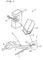
- a stripped terminal crimping machine like the conventional machine, comprises a stripping portion 3 for stripping a coating 2a at an end of each cable 2 sequentially fed; a terminal crimping portion 6 for crimping a crimp terminal 5 to a stripped part 4 of the cable 2 at the stripped end; a transport arm 7 for holding the cable 2 adjacent one end thereof for transporting the end of the cable 2 between the stripping portion 3 and the terminal crimping portion 6 in a reciprocal manner; and a terminated cable part inspection device 8 located on a bidirectional path P of the end of the cable 2.
- the stripping portion 3 suitably includes a cutting blade for severing the cable 2 and a stripping blade for cutting through the coating 2a, and is controlled to cut and strip the cable 2.
- the terminal crimping portion 6 includes a crimping machine.
- the terminal crimping portion 6 feeds successive crimp terminals 5 one by one to a crimping position in the crimping machine and is controlled to crimp one crimp terminal 5 to the stripped part 4.
- the transport arm 7 includes a cable clamp portion 7a for releasably holding the cable 2.
- the transport arm 7 is pivoted on a support shaft 9, with the cable 2 held by the cable clamp portion 7a, and is controlled to transport the end of the cable 2 in a reciprocal manner along the bidirectional path P at high speeds (for example, about 2000 mm/s).
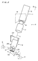
- the terminated cable part inspection device 8 includes an image pickup camera 11, such as a television camera and two-dimensional CCD camera, serving as an image pickup means for photographing the end of the cable 2 transported along the bidirectional path P; an illuminating means 12 for illuminating the end of the cable 2 transported along the bidirectional path P; and a detecting means 13 for detecting the photographing timing of the end of the cable 2 transported along the bidirectional path P.
- an image pickup camera 11 such as a television camera and two-dimensional CCD camera, serving as an image pickup means for photographing the end of the cable 2 transported along the bidirectional path P
- an illuminating means 12 for illuminating the end of the cable 2 transported along the bidirectional path P
- a detecting means 13 for detecting the photographing timing of the end of the cable 2 transported along the bidirectional path P.
- the image pickup camera 11 employs a camera having a superfast shutter function such that the shutter speed is fast (for example, 1/30000 sec.), and is angularly adjustably mounted at a predetermined angle to a mounting bracket 14 on the base of the stripped terminal crimping machine 1.
- the image pickup camera 11 includes a camera body 15, an extension tube 16, and a lens portion 17.
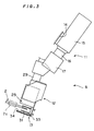
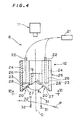
- the illuminating means 12 serves as an illuminating device according to the present invention and includes a pair of illuminating portions 20 located on opposite sides of a photographing path 19 of the image pickup camera 11 for directing illumination in substantially the same direction as the photographing direction of the image pickup camera 11 toward the end of the cable 2 passing therethrough along the bidirectional path P, a lamp housing 21 located in a separate position and includes a light source such as a halogen lamp, and optical fibers 22 made of quartz, plastic and the like for guiding the light emitted from the light source to the pair of illuminating portions 20.
- each optical fiber 22 adjacent the illuminating portions 20 is of a flat and fan-shaped configuration flared gradually toward the end.
- Light projecting portions 23 formed in the distal end surfaces of the optical fibers 22 are held by fiber array holders 24 so that they are elongated in substantially the same direction as the longitudinal direction of the cable 2 passing therethrough.
- the fiber array holders 24 are securely mounted in an illumination holder 25.
- the illumination holder 25 is of a hollow, cuboid-shaped configuration.
- the photographing path 19 defined by a rhombic aperture along an optical axis O of the image pickup camera 11 is formed centrally of the illumination holder 25.
- a pair of illuminating portion mounting apertures 26 are provided on opposite sides of the photographing path 19.
- the fiber array holders 24 are respectively inserted from above into the illuminating portion mounting apertures 26 and securely mounted in the illumination holder 25 with screws and the like.
- a pair of transmitted light scattering plates 27 made of ground glass or acrylic board for closing the respective illuminating portion mounting apertures 26 are securely mounted with screws and the like on the bottom of the illuminating portion mounting apertures 26 suitably spaced apart from the light projecting portions 23 of the optical fibers 22.
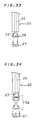
- the pair of transmitted light scattering plates 27 are inwardly inclined to form a suitable angle ⁇ a as shown in Fig. 4. Spacings surrounded by the light projecting portions 23 and transmitted light scattering plates 27 are defined as spacings 28 for diffusing the light guided by the optical fibers 22.
- the illumination holder 25 is mounted in a predetermined attitude to a mounting bracket 29 on the base of the stripped terminal crimping machine 1.
- the detecting means 13 includes a first sensor 31 for detecting the timing of photographing the end of the cable 2 transported in one direction (a first direction) along the bidirectional path P by the image pickup camera 11, and a second sensor 32 for detecting the timing of photographing the end of the cable 2 transported in the opposite direction (a second direction) along the bidirectional path P by the image pickup camera 11.
- the sensors 31, 32 are mounted to a sensor mounting bracket 33 in a position deviated from the optical axis O of the image pickup camera 11.
- Each of the sensors 31, 32 includes a light projector and a light receiver which are spaced apart in the direction of the optical axis O on opposite sides of the bidirectional path P as shown in Figs. 2 to 4.
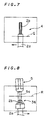
- a detecting position Q of the first sensor 31 is located in corresponding relation to the passing position of the end of the coating 2a of the stripped cable 2 as shown in Fig. 7, and a detecting position R of the second sensor 32 is located in corresponding relation to the passing position of an intermediate part of a core barrel part 5a serving as a core crimping part for crimping the crimp terminal 5 to a core part 2b as shown in Fig. 8.
- the photographing range of the image pickup camera 11 is shown in phantom in Figs. 7 and 8.
- An irregular reflector plate 34 serving as a sub-illuminating means is mounted over the bottom surface of the sensor mounting bracket 33 opposed to the illuminating portions 20 to direct illumination in the direction opposite from the illuminating portions 20 toward the end of the cable 2 passing therethrough along the bidirectional path P.
- the optical axis O of the image pickup camera 11 is slightly inclined toward the end surface at the end of the cable 2 from the direction orthogonal to the longitudinal direction of the cable 2 passing through the photographing position for ease of recognition as shown in Fig. 5.
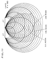
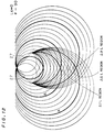
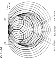
- Figs. 9, 10A, 10B, 11 through 32 illustrate illuminance distribution caused by the interference of illuminated light.
- the light sources are considered as surface light sources because of the function of the transmitted light scattering plates 27 of the illuminating portions 20.
- the points at which the two lines from the opposite ends of each of the transmitted light scattering plates 27 serving as the light sources form the same angle are plotted to form a curve on which a substantially uniform illuminance is provided.
- curves each indicative of a substantially uniform illuminance are drawn so that they are spaced 0.2L apart on the perpendicular bisector of the width L of each transmitted light scattering plate 27 to produce an illuminance distribution chart.
- the region surrounded by the curves which are 2.0L and 2.2L apart from the pair of transmitted light scattering plates 27 is defined as a 2.1L region
- the region surrounded by the curves which are 2.4L and 2.6L apart therefrom is defined as a 2.5L region
- the region surrounded by the curves which are 2.8L and 3.0L apart therefrom is defined as a 2.9L region.
- ⁇ X and ⁇ Y denote the horizontal and vertical lengths of the regions, respectively
- the effective approximate area ⁇ A of the regions is represented as ⁇ X ⁇ ⁇ Y/2 and the ratio ⁇ R of the horizontal length to the vertical length is represented as ⁇ X / ⁇ Y.
- Figs. 11 through 27 are illuminance distribution charts with variation in spacing La between the pair of transmitted light scattering plates 27 and variation in interior angle formed by the pair of transmitted light scattering plates 27, assuming that the unit L of the reference length is 100.
- Figs. 28 through 32 illustrate the relation between the values ⁇ X, ⁇ Y, ⁇ R, ⁇ A and the angle ⁇ for the respective regions.
- Figs. 11 through 13 are illuminance distribution charts when the spacing La between the pair of transmitted light scattering plates 27 equals zero and the interior angle ⁇ formed by the pair of transmitted light scattering plates 27 equals 180 degrees, 90 degrees, 60 degrees, respectively.
- Fig. 28 illustrates the relation between the values ⁇ X, ⁇ Y, ⁇ R, ⁇ A and the angle ⁇ when the spacing La equals zero.
- Figs. 14 through 17 are illuminance distribution charts when the spacing La between the pair of transmitted light scattering plates 27 equals 0.5L and the interior angle ⁇ formed by the pair of transmitted light scattering plates 27 equals 180 degrees, 120 degrees, 90 degrees, 60 degrees, respectively.
- Fig. 29 illustrates the relation between the values ⁇ X, ⁇ Y, ⁇ R, ⁇ A and the angle ⁇ when the spacing La equals 0.5L.
- Figs. 18 through 21 are illuminance distribution charts when the spacing La between the pair of transmitted light scattering plates 27 equals L and the interior angle ⁇ formed by the pair of transmitted light scattering plates 27 equals 180 degrees, 120 degrees, 90 degrees, 60 degrees, respectively.
- Fig. 30 illustrates the relation between the values ⁇ X, ⁇ Y, ⁇ R, ⁇ A and the angle ⁇ when the spacing La equals L.
- Figs. 22 through 24 are illuminance distribution charts when the spacing La between the pair of transmitted light scattering plates 27 equals 1.5L and the interior angle ⁇ formed by the pair of transmitted light scattering plates 27 equals 180 degrees, 90 degrees, 60 degrees, respectively.
- Fig. 31 illustrates the relation between the values ⁇ X, ⁇ Y, ⁇ R, ⁇ A and the angle ⁇ when the spacing La equals 1.5L.
- Figs. 25 through 27 are illuminance distribution charts when the spacing La between the pair of transmitted light scattering plates 27 equals 2L and the interior angle ⁇ formed by the pair of transmitted light scattering plates 27 equals 180 degrees, 90 degrees, 60 degrees, respectively.
- Fig. 32 illustrates the relation between the values ⁇ X, ⁇ Y, ⁇ R, ⁇ A and the angle ⁇ when the spacing La equals 2L.
- the effective approximate area ⁇ A having a substantially uniform illuminance, the horizontal length ⁇ X along the bidirectional path P, and the ratio ⁇ R of the horizontal length ⁇ X to the vertical length ⁇ Y are maximum when the interior angle ⁇ formed by the transmitted light scattering plates 27 ranges from about 120 to about 160 degrees.
- the effective approximate area ⁇ A having a substantially uniform illuminance, the horizontal length ⁇ X along the bidirectional path P, and the ratio ⁇ R of the horizontal length ⁇ X to the vertical length ⁇ Y are maximum when the interior angle ⁇ formed by the transmitted light scattering plates 27 ranges from about 90 to about 150 degrees.
- the effective approximate area ⁇ A having a substantially uniform illuminance, the horizontal length ⁇ X along the bidirectional path P, and the ratio ⁇ R of the horizontal length ⁇ X to the vertical length ⁇ Y are maximum when the interior angle ⁇ formed by the transmitted light scattering plates 27 ranges from about 70 to about 130 degrees.
- the effective approximate area ⁇ A having a substantially uniform illuminance, the horizontal length ⁇ X along the bidirectional path P, and the ratio ⁇ R of the horizontal length ⁇ X to the vertical length ⁇ Y are maximum when the interior angle ⁇ formed by the transmitted light scattering plates 27 ranges from about 40 to about 110 degrees.
- the effective approximate area ⁇ A having a substantially uniform illuminance, the horizontal length ⁇ X along the bidirectional path P, and the ratio ⁇ R of the horizontal length ⁇ X to the vertical length ⁇ Y are maximum when the interior angle ⁇ formed by the transmitted light scattering plates 27 ranges from about 30 to about 90 degrees.
- the angle ⁇ a of inward inclination of the transmitted light scattering plates 27 which is suitable for photographing may be selected as required so as to provide the suitable effective approximate area ⁇ A and horizontal length ⁇ X of the region lying in the position along the bidirectional path P in accordance with the determined relation between the spacing between the transmitted light scattering plates 27 and the position of the bidirectional path P.
- the end of the cable 2 fed from a cable feeding portion not shown to the cable clamp portion 7a of the transport arm 7 is held by the cable clamp portion 7a and subjected to the stripping of the coating 2a in the stripping portion 3.
- the transport arm 7 Upon completion of the stripping, the transport arm 7 is pivoted on the support shaft 9 to transport the stripped part 4 at the end of the cable 2 in the first direction from an initial position of the bidirectional path P.
- the first sensor 31 detects the end of the cable 2 to actuate a timer, and the image pickup camera 11 is controlled so that the shutter fires when the stripped part 4 passes through the position of the optical axis O.
- the transport arm 7 is pivoted on the support shaft 9 to transport a terminal crimped part 36 at the end of the cable 2 in the second direction along the bidirectional path P from the terminal crimping portion 6.
- the second sensor 32 detects the end of the cable 2 to actuate the timer, and the image pickup camera 11 is controlled so that the shutter fires when the terminal crimped part 36 passes through the position of the optical axis O.
- the cable 2 On arrival at the initial position in the stripping portion 3, the cable 2 is transported by a predetermined length in a predetermined direction and cut in position.
- the stripping and terminal crimping are repeatedly performed on successive cables 2 in sequential order in the same fashion, and the stripped part 4 and terminal crimped part 36 of the successive cables 2 are photographed during the transport of the end thereof and subjected to the conventional image processing and judgement whether the stripping and crimping conditions are defective or not.
- the illuminating portions 20 are provided on opposite sides of the photographing path 19 of the image pickup camera 11 to direct illumination in substantially the same direction as the photographing direction of the image pickup camera 11 toward the end of the cable 2 passing therethrough along the bidirectional path P, and each of the illuminating portions 20 is elongated in substantially the same direction as the longitudinal direction of the transported cable 2.
- the pair of illuminating portions 20 which are arranged to form the suitable angle ⁇ a direct illumination in inwardly angled directions from the opposite sides of the photographing path 19 of the image pickup camera 11 toward the end of the cable 2 passing along the bidirectional path P.
- a sufficient illuminance for photographing the end of the cable 2 moved along the bidirectional path P is satisfactorily ensured when differences in photographing attitude and passing position along the bidirectional path P occur between the stripped end of the cable 2 moved in the first direction and the end of the cable 2 with the crimp terminal 5 crimped thereto and moved in the second direction and when the diameter of the cable 2 and the type of the crimp terminal 5 are varied.
- This allows the high-shutter-speed image pickup camera 11 to satisfactorily capture the reflected image of the end of the cable 2 moving at high speeds, thereby providing a great amount of image information and achieving inspection using more correct image information and improvement in inspection reliability.
- the light emitted from the light source in the lamp housing 21 located in a vacant spacing in the separate position is designed to be guided to the light projecting portions 23 of the illuminating portions 20 by the optical fibers 22, permitting the illuminating portions 20 which are compact in size to be readily incorporated in a small spacing in the stripped terminal crimping machine 1 in closer proximity to the bidirectional path P of the end of the cable 2. This insures a sufficient brightness and the size reduction of the terminated cable part inspection device 8 itself incorporated in the stripped terminal crimping machine 1.
- the detecting position of the first sensor 31 is located in corresponding relation to the passing position of the end of the coating 2a at the stripped end of the cable 2, the passage of the end of the cable 2 which might suffer a failure such as disconnection of the core part 2b is satisfactorily detected.
- the detecting position R of the second sensor 32 is located in corresponding relation to the passing position of the intermediate part of the core barrel part 5a of the crimped crimp terminal 5, the detecting position R is a generally intermediate position of the photographing range as shown in Fig. 8, which can effectively solve the yawing problem of the crimp terminal 5. This provides good photographing timing by the image pickup camera 11, whether the cable 2 be transported in the first or second direction along the bidirectional path P, and stabilized image capturing.
- the end of the cable 2 held in cantilevered fashion by the cable clamp portion 7a during the high-speed transport causes the distal end of the stripped part 4 to deflect slightly rearwardly in the transport direction when transported in the first direction along the bidirectional path P.
- the end of the cable 2 weighted by the crimp terminal 5 crimped thereto when transported in the second direction along the bidirectional path P causes the distal end of the terminal crimped part 36 to deflect by a greater amount rearwardly in the opposite transport direction.
- the provision of the respective purpose-built first and second sensors 31 and 32 can provide good photographing timing by the image pickup camera 11 and stabilized image capturing.
- the light diffusing spacings 28 between the light projecting portions 23 and the transmitted light scattering plates 27 can produce uniformly scattered light for the end of the cable 2 passing along the bidirectional path P to provide illumination of high brightness. Such a structure that the diffusing spacings 28 are merely provided may reduce the costs.
- the photographing path 19 of the illumination holder 25 is of rhombic configuration, and the transmitted light scattering plates 27 close the illuminating portion mounting apertures 26 on opposite sides of the photographing path 19 and are mounted and fixed in inwardly inclined relation.
- Such an arrangement ensures a greater light projection area of the transmitted light scattering plates 27 than the structure having the rectangular photographing path 19 and the structure having the parallel transmitted light scattering plates 27 which form 180 degrees. This provides for total improvement in illuminance at the photographing position, accordingly achieving the inspection using more correct image information and the improvement in inspection reliability.
- one or more condenser lenses 38 may be suitably provided between the light projecting portion 23 and transmitted light scattering plate 27 to guide the light from the light projecting portion 23 in a direction at right angles to the transmitted light scattering plate 27. This provides illumination of higher illuminance by more uniformly scattered light.
- the illuminating portions 20 are mounted in the illuminating portion mounting apertures 26 of the illumination holder 25 in the preferred embodiment. However, the illuminating portions 20 may be separately independently mounted to the base of the stripped terminal crimping machine 1.
- FIG. 35 An example of the image of the terminal crimped part 36 transported in the second direction is shown in Fig. 35.
- the shaded portions of Fig. 35 are specular reflection parts. Specular reflection is also provided in the core part 2b between a resin barrel part 5b and the core barrel part 5a. The specular reflection parts are extracted as shown in Fig. 36.
- bellmouths are formed on opposite ends of the core barrel part 5a to release the stresses during the crimping of the crimp terminal 5.
- the bellmouths sharpen the boundary between the end of the specular reflection parts in the core barrel part 5a and the core part 2b.
- Reference points for the image processing are derived by the image processing means by means of the run-length encoding technique which is detailed in the specification and accompanying drawings of Japanese Patent Application No. 3-268771 (1991) applied by the applicant of the present invention and which is based on the derivation of the configuration and the like of the crimp terminal 5 to be processed from the changes in white and black information along one scanning line.
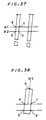
- two linear windows W1, W2 are established in the middle of the image of the specular reflection parts in the core barrel part 5a as shown in Fig. 37.
- the points a, b, c, d of intersection of the windows W1, W2 and the borders of the specular reflection parts are derived.
- the gradient of the specular reflection parts is determined from the gradient of the line segment ab connecting the points a and b.
- a window W3 is established which extends from the mid-point of the line segment ac or any intermediate point on the line segment ac with a gradient of the line segment ab.
- a point A of change in brightness is derived on the window W3 and serves as one of the reference points required for the image processing.
- other reference points B, C, D, E, F, G, H shown in Fig. 36 are derived.
- the barrel parts 5a and 5b are not completely formed in a cylindrical shape and provide incomplete specular surfaces to cause a geometrically unstable shape of the specular reflection parts. It is hence impracticable to determine the reference points during one process shown in Figs. 37 and 38, and the reference points are in practice determined by repeating the process twice or three times.
- a reference point A' is not located at the end of the specular reflection part.
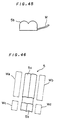
- the windows W1, W2 are re-established at the positions shifted by several pixels from the derived reference point A' and the similar operation is repeated to derive the point of change in brightness on the window W3 as shown in Fig. 40.
- the configuration, size and gradient of the crimp terminal 5 are determined on the basis of the reference points A to H, and a judgement is made whether or not the crimping conditions of the crimp terminal 5 are defective on the basis of the position of the end of the coating 2a between the resin barrel part 5b and core barrel part 5a and the length of projecting core part 2b between the core barrel part 5a and a front end connecting portion.
- the attitude of the crimp terminal 5 need not be completely the same because of the correct derivation of the reference points A to H. This allows an acceptable level of rough arrangement of the crimp terminal 5 to be inspected. A stable image is obtained if the crimp terminal 5 falls within the photographing range of the image pickup camera 11.
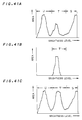
- a distribution curve based on an area versus received light intensity histogram for an image of the crimp terminal 5 crimped to a blue cable 2 illuminated by the illuminating means 12 is shown, for example, in Fig. 41A wherein the abscissa is a brightness level indicated by 256 gradations and the ordinate is the area (the number of pixels).
- the region of high brightness level corresponds to a specular reflection region S in the barrel parts 5a, 5b of the crimp terminal 5
- the region of intermediate brightness level corresponds to a resin region T of the coating 2a of the cable 2
- the region of low brightness level corresponds to a non-specular reflection region U of the crimp terminal 5.
- the distribution curve of Fig. 41A based on the area versus received light intensity histogram, there are valleys between the specular reflection region S and resin region T and between the resin region T and non-specular reflection region U.
- FIG. 41B A distribution curve based on an area versus received light intensity histogram for a background image including no crimp terminal 5 is shown in Fig. 41B.
- the irregular reflector plate 34 is selected so that the background region T' is positioned intermediate the specular reflection region S and non-specular reflection region U of Fig. 41A.
- Fig. 41C The synthesis of the distribution curves of Figs. 41A and 41B based on the area versus received light intensity histograms is shown in Fig. 41C.
- Fig. 41C there are peaks in the specular reflection region S, background region T', and non-specular reflection region U, and there are valleys between the regions S and T' and between the regions T' and U, similarly to Fig. 41A.
- a typical distribution curve based on the area versus received light intensity histogram for the crimp terminal 5 is previously determined, and binary levels may be set between the specular reflection region S and background region T' and between the background region T' and non-specular reflection region U, that is, in the valleys of the distribution curve.
- Figs. 42A and 42B Distribution curves based on area versus received light intensity histograms when the cable 2 is white and black are shown in Figs. 42A and 42B, respectively.
- the peak in the resin region T is shifted toward the specular reflection region S as compared with the blue cable (Fig. 41A) and there is a small valley between the regions S and T.
- the black cable the peak in the resin region T is shifted toward the non-specular reflection region U as compared with the blue cable, and the resin region T and non-specular reflection region U overlap so that the distinction therebetween is blurry.
- the binary level may be set between the specular reflection region S and resin region T by regulating the illumination intensity using the diaphragm of the lens of the image pickup camera 11. This allows the setting of two different binary levels, that is, the above stated binary level between the specular reflection region S and resin region T and the binary level between the resin region T and non-specular reflection region U.
- one binary level is reliably set in a wide, distinct valley between the resin and non-specular reflection regions T, U and the specular reflection region S.
- two binary levels may be set for the while cable 2, similar to the blue cable, by previously determining the typical distribution curve based on the area versus received light intensity histogram for the crimp terminal 5.
- the black cable although one binary level may be definitely set on the basis of the distribution curve, another binary level may be readily set in a low brightness level region, if required, on the basis of various distribution curves based on area versus received light intensity histograms.
- the setting of two different binary levels on the basis of the distribution curve based on the area versus received light intensity histogram for the image of the crimp terminal 5 toward which illumination is directed by the illuminating portions 20 and irregular reflector plate 34 in opposite directions insures the detection of the core part 2b extending off, particularly the core part 2b extending off sidewise.
- Fig. 43B is a front view of Fig. 43A which is a plan view.
- the illuminating portions 20 and irregular reflector plate 34 direct illumination in the opposite directions toward the crimp terminal 5 to obtain an image of the crimp terminal 5.
- rectangular windows Wa, Wb are established on opposite sides of the core barrel part 5a and rectangular windows Wc, Wd are similarly established on opposite sides of the resin barrel part 5b.
- the distribution curve based on the area versus received light intensity histogram for the windows Wa to Wd is shown in Fig. 47 if the core M does not extend off. In the distribution curve of Fig. 47, there is a peak only in the background region T', and no peaks appear in the regions S and U.
- the core M extending off sidewise from the crimp terminal 5 generates a peak in the region S or U in addition to the peak in the background region T' in the distribution curve for any of the windows Wa to Wd.
- the binary processing is performed on the brightness of each pixel in each of the windows Wa to Wd on the basis of the binary levels set between the regions S and T' and between regions T' and U, and the presence of a pixel having a brightness higher than the higher binary level between the regions S and T' and a pixel having a brightness lower than the lower binary level between the regions T' and U is detected, thereby detecting the core M extending off sidewise from the crimp terminal 5 in any direction.
- failures may be detected as a result of the image processing, for example, the above stated core extending-off failure, a so-called pressing failure in which the resin barrel part 5b is open, and a short core failure in which no end of the core part 2b extends from the core barrel part 5a. These failures detected are subjected to suitable corrective actions.
- the image processing of the terminal crimped part 36 fed in the second direction along the bidirectional path P has been described above, the image processing of the stripped part 4 fed in the first direction therealong may be similarly performed.
Landscapes
- Physics & Mathematics (AREA)
- General Physics & Mathematics (AREA)
- Investigating Materials By The Use Of Optical Means Adapted For Particular Applications (AREA)
Applications Claiming Priority (3)
| Application Number | Priority Date | Filing Date | Title |
|---|---|---|---|
| JP6320789A JP3008796B2 (ja) | 1994-12-22 | 1994-12-22 | 皮剥端子圧着機の電線処理部検査装置における照明方法および照明装置 |
| JP320789/94 | 1994-12-22 | ||
| JP32078994 | 1994-12-22 |
Publications (3)
| Publication Number | Publication Date |
|---|---|
| EP0718594A2 true EP0718594A2 (de) | 1996-06-26 |
| EP0718594A3 EP0718594A3 (de) | 1998-03-11 |
| EP0718594B1 EP0718594B1 (de) | 2002-11-13 |
Family
ID=18125266
Family Applications (1)
| Application Number | Title | Priority Date | Filing Date |
|---|---|---|---|
| EP95120147A Expired - Lifetime EP0718594B1 (de) | 1994-12-22 | 1995-12-20 | Verfahren und Vorrichtung zur Beleuchtung im Endstückinspektionsteil einer Drahtendstückproduktionsmaschine |
Country Status (4)
| Country | Link |
|---|---|
| US (1) | US5619792A (de) |
| EP (1) | EP0718594B1 (de) |
| JP (1) | JP3008796B2 (de) |
| DE (1) | DE69528810T2 (de) |
Cited By (1)
| Publication number | Priority date | Publication date | Assignee | Title |
|---|---|---|---|---|
| CN107902923A (zh) * | 2017-11-21 | 2018-04-13 | 杭州富通通信技术股份有限公司 | 涂覆系统及其供料装置 |
Families Citing this family (13)
| Publication number | Priority date | Publication date | Assignee | Title |
|---|---|---|---|---|
| JP3731783B2 (ja) * | 1997-09-05 | 2006-01-05 | 矢崎総業株式会社 | 端子の圧着方法および圧着装置 |
| JP5460527B2 (ja) | 2009-11-19 | 2014-04-02 | 新明和工業株式会社 | 被覆電線検査装置およびそれを備えた電線処理機 |
| CN102095735B (zh) * | 2009-11-19 | 2014-06-11 | 新明和工业株式会社 | 包覆电线检查装置以及具备该装置的电线处理机 |
| GB2478928B (en) * | 2010-03-23 | 2014-04-23 | Circuitmaster Designs Ltd | An apparatus and method for feeding crimp terminals on a carrier strip into a crimping press |
| EP2709217B1 (de) * | 2012-09-12 | 2017-08-09 | Schleuniger Holding AG | Maschine für die Montage von Kabeltüllen |
| CN104158050B (zh) * | 2014-06-30 | 2016-03-09 | 苏州朗誉电子科技有限公司 | 高速通讯同轴电缆压接装置及具有该压接装置的压接机 |
| WO2017043270A1 (ja) * | 2015-09-09 | 2017-03-16 | 住友電装株式会社 | 端子付電線の検査方法及び端子付電線検査装置 |
| EP3611493B1 (de) * | 2018-08-13 | 2025-05-14 | Komax Holding Ag | Überprüfungsvorrichtung zum überprüfen einer kabelspitze eines kabels und verfahren zum reinigen |
| JP7140732B2 (ja) | 2019-09-20 | 2022-09-21 | 矢崎総業株式会社 | 圧着端子の外観検査装置 |
| JP7164560B2 (ja) * | 2020-03-30 | 2022-11-01 | 矢崎総業株式会社 | 圧着端子の外観検査装置 |
| TWI855329B (zh) * | 2022-05-24 | 2024-09-11 | 鴻海精密工業股份有限公司 | 檢測系統 |
| EP4462615A1 (de) * | 2023-05-09 | 2024-11-13 | komax Holding AG | Kabelverarbeitungsmaschine und verfahren zum betreiben einer kabelverarbeitungsmaschine |
| CN118738979B (zh) * | 2024-09-03 | 2024-11-05 | 国网安徽省电力有限公司灵璧县供电公司 | 一种电缆连接器压合装置 |
Family Cites Families (12)
| Publication number | Priority date | Publication date | Assignee | Title |
|---|---|---|---|---|
| US2805471A (en) * | 1953-09-25 | 1957-09-10 | Ncr Co | Method for locating paths of wires on lacing board |
| US3913202A (en) * | 1973-08-10 | 1975-10-21 | Questech Inc | Apparatus for making electrical wiring harnesses |
| JPS61133844A (ja) * | 1984-12-03 | 1986-06-21 | Shin Meiwa Ind Co Ltd | 端子圧着電線の端子圧着部検査方法 |
| DE3823836A1 (de) * | 1988-07-14 | 1990-01-18 | Fraunhofer Ges Forschung | Verfahren zum vermessen von der bestueckung von leiterplatten dienenden bauelementen und einrichtung zur durchfuehrung des verfahrens |
| JP2517381B2 (ja) * | 1989-01-18 | 1996-07-24 | 新明和工業株式会社 | 圧着端子の圧着状態検査装置 |
| CA2044649A1 (en) * | 1990-06-19 | 1991-12-20 | Masanori Nishiguchi | Method and apparatus for packaging a semiconductor device |
| US5249349A (en) * | 1991-01-24 | 1993-10-05 | Matsushita Electric Works, Ltd. | Parts mounting device |
| US5185638A (en) * | 1991-04-26 | 1993-02-09 | International Business Machines Corporation | Computer controlled, multiple angle illumination system |
| JP2795044B2 (ja) * | 1992-03-26 | 1998-09-10 | 住友電装株式会社 | 圧着端子画像処理検査における照明方法及び画像処理方法 |
| JP2707922B2 (ja) * | 1992-08-03 | 1998-02-04 | 日立電線株式会社 | 軟質ホース自動挿入装置 |
| IE940607A1 (en) * | 1993-08-02 | 1995-02-08 | Motorola Inc | A bottom lighting system for use with a conveyer system |
| EP0702227B1 (de) * | 1994-09-14 | 1998-12-02 | Sumitomo Wiring Systems, Ltd. | Vorrichtung zur Untersuchung von Kabelenden in Maschinen zum Abisolieren und Anquetschen von Kabeln |
-
1994
- 1994-12-22 JP JP6320789A patent/JP3008796B2/ja not_active Expired - Lifetime
-
1995
- 1995-12-14 US US08/572,419 patent/US5619792A/en not_active Expired - Fee Related
- 1995-12-20 EP EP95120147A patent/EP0718594B1/de not_active Expired - Lifetime
- 1995-12-20 DE DE69528810T patent/DE69528810T2/de not_active Expired - Fee Related
Cited By (2)
| Publication number | Priority date | Publication date | Assignee | Title |
|---|---|---|---|---|
| CN107902923A (zh) * | 2017-11-21 | 2018-04-13 | 杭州富通通信技术股份有限公司 | 涂覆系统及其供料装置 |
| CN107902923B (zh) * | 2017-11-21 | 2021-02-19 | 杭州富通通信技术股份有限公司 | 涂覆系统及其供料装置 |
Also Published As
| Publication number | Publication date |
|---|---|
| DE69528810T2 (de) | 2003-03-20 |
| JP3008796B2 (ja) | 2000-02-14 |
| JPH08178851A (ja) | 1996-07-12 |
| EP0718594A3 (de) | 1998-03-11 |
| EP0718594B1 (de) | 2002-11-13 |
| US5619792A (en) | 1997-04-15 |
| DE69528810D1 (de) | 2002-12-19 |
Similar Documents
| Publication | Publication Date | Title |
|---|---|---|
| US5691763A (en) | Terminated cable portion inspection device for stripped terminal crimping machine | |
| US5619792A (en) | Method and device for illumination in terminated cable part inspection device for stripped terminal crimping machine | |
| EP0501683B1 (de) | Verfahren zur Verbesserung von zweidimensionalen Bildern | |
| JP2001255281A (ja) | 検査装置 | |
| JP3021266B2 (ja) | 光学式鋼板表面検査装置 | |
| US5377278A (en) | Method and apparatus for inspecting a solderless terminal by image processing | |
| JP3935048B2 (ja) | 被覆電線検査装置 | |
| JP3002389B2 (ja) | 皮剥端子圧着機における電線処理部検査装置 | |
| JP2505969B2 (ja) | 被覆電線の皮剥き検査装置 | |
| US6128034A (en) | High speed lead inspection system | |
| JPH11248643A (ja) | 透明フィルムの異物検査装置 | |
| JP3002388B2 (ja) | 皮剥端子圧着機における電線処理部検査装置 | |
| JPH02189880A (ja) | 圧着端子の圧着状態検査装置 | |
| JPH07117391B2 (ja) | 照明ランプにおける端子のカシメ部の検査装置 | |
| JPS61213709A (ja) | 電子部品外観検査方法 | |
| JP2996063B2 (ja) | 塗装面鮮映性自動検査装置 | |
| JPH06242020A (ja) | 表面欠陥検査装置 | |
| JP3831498B2 (ja) | 光学部材検査装置 | |
| JPH05249043A (ja) | 圧着端子画像処理検査における照明方法 | |
| JPH0310064B2 (de) | ||
| JP2000002526A (ja) | 表面欠陥の検査方法および検査装置 | |
| JPS60174962A (ja) | 処理された電線端末の検査方法および装置 | |
| JPH05144915A (ja) | リード検査用の撮像装置 | |
| JPH10284898A (ja) | 半田ブリッジ検査装置 | |
| JPS63196053A (ja) | Ic外観検査方法 |
Legal Events
| Date | Code | Title | Description |
|---|---|---|---|
| PUAI | Public reference made under article 153(3) epc to a published international application that has entered the european phase |
Free format text: ORIGINAL CODE: 0009012 |
|
| AK | Designated contracting states |
Kind code of ref document: A2 Designated state(s): DE GB |
|
| 17P | Request for examination filed |
Effective date: 19970528 |
|
| PUAL | Search report despatched |
Free format text: ORIGINAL CODE: 0009013 |
|
| AK | Designated contracting states |
Kind code of ref document: A3 Designated state(s): DE GB |
|
| 17Q | First examination report despatched |
Effective date: 20000914 |
|
| GRAG | Despatch of communication of intention to grant |
Free format text: ORIGINAL CODE: EPIDOS AGRA |
|
| GRAG | Despatch of communication of intention to grant |
Free format text: ORIGINAL CODE: EPIDOS AGRA |
|
| GRAH | Despatch of communication of intention to grant a patent |
Free format text: ORIGINAL CODE: EPIDOS IGRA |
|
| GRAH | Despatch of communication of intention to grant a patent |
Free format text: ORIGINAL CODE: EPIDOS IGRA |
|
| GRAA | (expected) grant |
Free format text: ORIGINAL CODE: 0009210 |
|
| AK | Designated contracting states |
Kind code of ref document: B1 Designated state(s): DE GB |
|
| REG | Reference to a national code |
Ref country code: GB Ref legal event code: FG4D |
|
| REF | Corresponds to: |
Ref document number: 69528810 Country of ref document: DE Date of ref document: 20021219 |
|
| PLBE | No opposition filed within time limit |
Free format text: ORIGINAL CODE: 0009261 |
|
| STAA | Information on the status of an ep patent application or granted ep patent |
Free format text: STATUS: NO OPPOSITION FILED WITHIN TIME LIMIT |
|
| 26N | No opposition filed |
Effective date: 20030814 |
|
| PGFP | Annual fee paid to national office [announced via postgrant information from national office to epo] |
Ref country code: GB Payment date: 20041215 Year of fee payment: 10 |
|
| PGFP | Annual fee paid to national office [announced via postgrant information from national office to epo] |
Ref country code: DE Payment date: 20041216 Year of fee payment: 10 |
|
| PG25 | Lapsed in a contracting state [announced via postgrant information from national office to epo] |
Ref country code: GB Free format text: LAPSE BECAUSE OF NON-PAYMENT OF DUE FEES Effective date: 20051220 |
|
| PG25 | Lapsed in a contracting state [announced via postgrant information from national office to epo] |
Ref country code: DE Free format text: LAPSE BECAUSE OF NON-PAYMENT OF DUE FEES Effective date: 20060701 |
|
| GBPC | Gb: european patent ceased through non-payment of renewal fee |
Effective date: 20051220 |