EP0204599B1 - Verfahren und Vorrichtung zur Bestimmung des Kennzeichens von grosser Distanz einer seismischen Sendergruppe - Google Patents
Verfahren und Vorrichtung zur Bestimmung des Kennzeichens von grosser Distanz einer seismischen Sendergruppe Download PDFInfo
- Publication number
- EP0204599B1 EP0204599B1 EP86401013A EP86401013A EP0204599B1 EP 0204599 B1 EP0204599 B1 EP 0204599B1 EP 86401013 A EP86401013 A EP 86401013A EP 86401013 A EP86401013 A EP 86401013A EP 0204599 B1 EP0204599 B1 EP 0204599B1
- Authority
- EP
- European Patent Office
- Prior art keywords
- sources
- transmission
- signatures
- signature
- catalogue
- Prior art date
- Legal status (The legal status is an assumption and is not a legal conclusion. Google has not performed a legal analysis and makes no representation as to the accuracy of the status listed.)
- Expired
Links
- 238000000034 method Methods 0.000 title claims description 15
- 238000005259 measurement Methods 0.000 claims description 22
- 230000005540 biological transmission Effects 0.000 claims description 19
- 238000007654 immersion Methods 0.000 claims description 17
- XLYOFNOQVPJJNP-UHFFFAOYSA-N water Substances O XLYOFNOQVPJJNP-UHFFFAOYSA-N 0.000 claims description 10
- 230000003321 amplification Effects 0.000 claims description 4
- 238000003199 nucleic acid amplification method Methods 0.000 claims description 4
- 238000012545 processing Methods 0.000 claims description 4
- 230000000977 initiatory effect Effects 0.000 claims 1
- 238000002955 isolation Methods 0.000 description 6
- 230000003993 interaction Effects 0.000 description 4
- 230000001960 triggered effect Effects 0.000 description 4
- 238000010586 diagram Methods 0.000 description 3
- 238000012986 modification Methods 0.000 description 3
- 230000004048 modification Effects 0.000 description 3
- 239000006185 dispersion Substances 0.000 description 2
- 238000002592 echocardiography Methods 0.000 description 2
- 238000010304 firing Methods 0.000 description 2
- 239000012530 fluid Substances 0.000 description 2
- 230000002706 hydrostatic effect Effects 0.000 description 2
- 239000007788 liquid Substances 0.000 description 2
- 230000015572 biosynthetic process Effects 0.000 description 1
- 230000008602 contraction Effects 0.000 description 1
- 238000012937 correction Methods 0.000 description 1
- 238000007599 discharging Methods 0.000 description 1
- 230000000694 effects Effects 0.000 description 1
- 239000003380 propellant Substances 0.000 description 1
- 230000006798 recombination Effects 0.000 description 1
- 238000005215 recombination Methods 0.000 description 1
- 230000035939 shock Effects 0.000 description 1
- 238000003786 synthesis reaction Methods 0.000 description 1
Images
Classifications
-
- G—PHYSICS
- G01—MEASURING; TESTING
- G01V—GEOPHYSICS; GRAVITATIONAL MEASUREMENTS; DETECTING MASSES OR OBJECTS; TAGS
- G01V13/00—Manufacturing, calibrating, cleaning, or repairing instruments or devices covered by groups G01V1/00 – G01V11/00
Definitions
- the subject of the invention is a method for determining the long-distance signature of a set of emission of seismic pulses in water, comprising a plurality of combined seismic sources and in particular of a set of seismic sources operating by implosion, and a device for its implementation.
- the emission into the water of seismic pulses can be obtained for example by the sudden contraction of an immersed cavity where there is a very low pressure compared to the hydrostatic pressure.
- This cavity can be delimited by the walls of an enclosure of variable volume of the type described for example in French patent FR-A 1,583,737.
- the seismic pulses generated have a shape which depends on the type of source used, on its mechanical characteristics, possibly on the pressure of the propellant hydraulic fluid allowing the ejection of liquid, and also on its depth of immersion.
- the shape of the seismic pulses generated by a determined source which constitutes the emission signature of the latter, is generally well reproducible under defined conditions of use and depends only on the depth of immersion. It is determined by means of a pressure sensor located nearby.
- a known method for determining the global signature of a set of combined sources consists in immersing as many pressure sensors as there are sources, the position of the sensors relative to these being known, in processing their different measurements taking account for interactions so as to determine the equivalent signatures of the sources, corrected for interaction effects, and to superimpose the corrected signatures to obtain the global signature over a long distance.
- the method according to the invention makes it possible to determine the global long distance transmission signature of a transmission assembly comprising a number N of combined sources, which does not have the drawbacks indicated above.
- the parameters influencing the shape of the pulses produced are the depth and possibly other parameters depending on the type of source used.
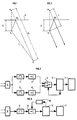
- the signature of a source e i is the variation as a function of time t of the pressure measured by the sensor H resulting from the acoustic pulse emitted by the source after its triggering (Fig. 1).
- the close signature if (or "near field”) is measured at a reference distance ri of the order of 1 meter for example.
- the signature of the source measured at a certain distance below the source, is a combination of the pulse which propagates directly from ei to H with that, generally designated by "phantom” which reaches the sensor shifted in time after reflection at a point M i on the water / air interface 1.
- the distant signature S H (or "far field") of a set of N sources ei, measured by the hydrophone H is expressed in a known manner by the relation: s i is the signature of the source e i , r i and R i are the distances eiH and e i M i H respectively, and P is the reflection coefficient of the water / air interface which is very little different from -1 .
- the signature S at infinity or at least at very great distance (Fig. 2), of an emission assembly made up of a number N of sources at implosion, ei, e 2 ... e N triggered in sequence so as to bring their implosion peaks into phase is a linear combination of signatures if from different sources e; considered in isolation and is expressed by a relation of the type: where I i represents the projection, on the direction of recombination, of the distance between each source e i and its image e'i. This relationship is independent of the geometry of the emission assembly, that is to say of the relative position of the different sources with respect to each other and their interactions.
- the method according to the invention comprises the prior measurement of the emission signatures of each of the sources ei actuated in isolation by a hydrophone placed at a short distance (1 meter for example) for different values of parameters influencing the shape of the pulses produced.
- the main parameter is the depth of immersion.
- the measured emission signatures are preferably corrected so as to eliminate from them the contributions due to reflections on the water / air interface 1 ("ghosts").
- the two stages of correction or modification of signatures before their inclusion in the catalog to eliminate the contribution of the ghost to infinity are optional. They can also be carried out both at the time of the constitution of the catalog, so as to collect in it copies of infinite signatures ready for combinations.
- the implementation of the method is advantageously carried out using reception means suitable for alternately measuring the immersion depth of each source and its emission signature, the immersion depth at the precise moment of its triggering being determined by combination of the depth measurements before and after the moment of "firing".
- the device for implementing the method comprises, for each of the sources, a single sensor H placed nearby and connected to the input of an acquisition system shown in FIG. 3.
- the signal supplied by the sensor H is applied to the input of two different amplification channels, each comprising a bandpass filter 1, 2 and an amplifier 3, 4.
- the two amplifiers 3, 4 have different gains g 1 and g 2 .
- the signals which they deliver are applied to two inputs of an electronic switch 5, the output of this being connected to the input of a digitization and recording assembly 6.
- This comprises means for memorizing the different emission signatures constituting the catalog and means for delivering a control signal from the switch 5, making it possible to select one or the other of the signals coming from the amplifiers 3 or 4.
- a computer 7 is connected to the digitization and recording assembly 6. It is suitable for carrying out the combinations of emission signatures selected from the catalog to synthesize the global signature ad infinitum of all the sources.
- the gain of the amplifier 3 is chosen to be large enough so that the signal which it delivers constitutes an accurate measurement of the hydro static pressure and consequently of the depth of immersion of the associated source.
- amplifier 4 is chosen lower so that the signal at its output faithfully and without clipping restores the variations in pressure generated by the source when it is triggered.
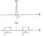
- a source having to be triggered at an instant t (Fig. 5), a measurement is made of the depth of immersion at an anterior instant t i and at a posterior instant t 2 (Fig. 6).
- the assembly 6 applies to the switch 5 at times t 1 and t 2 and during a time interval or window AT, a control signal making it possible to select the amplifier 3.
- the two depth measurements which frame the triggering instant t are successively memorized and the computer 7 interpolates between them, so as to precisely determine the depth of immersion of the source at the time of the "firing". Outside these two depth measurement windows, the switch is controlled to select the signal delivered by the amplifier 4 which translates the emission signature of the source.
- the acquisition system can comprise a single amplification channel comprising a band-pass filter 8 and a variable gain amplifier 9 whose gain can take at least two gain values different g 1 , g 2 according to the control signal applied to it by a gain control element 10 controlled by the recording assembly 6.
- the gain g i allowing a fine measurement of the immersion depth is applied to the amplifier 9 at instants t 1 and t 2 and during a time interval eT.
- the gain g 2 is applied outside of the measurement windows, so as to obtain the emission signature of the source.
- the computer 7 determines the precise value of the immersion depth by interpolations between the values measured at times t 1 and t 2 .
Landscapes
- Engineering & Computer Science (AREA)
- Manufacturing & Machinery (AREA)
- Physics & Mathematics (AREA)
- Life Sciences & Earth Sciences (AREA)
- General Life Sciences & Earth Sciences (AREA)
- General Physics & Mathematics (AREA)
- Geophysics (AREA)
- Geophysics And Detection Of Objects (AREA)
- Arrangements For Transmission Of Measured Signals (AREA)
- Measurement Of Mechanical Vibrations Or Ultrasonic Waves (AREA)
Claims (7)
Applications Claiming Priority (2)
| Application Number | Priority Date | Filing Date | Title |
|---|---|---|---|
| FR8507582A FR2582107B1 (fr) | 1985-05-17 | 1985-05-17 | Procede et dispositif pour la determination de la signature d'emission a grande distance d'un ensemble d'emission sismique |
| FR8507582 | 1985-05-17 |
Publications (2)
| Publication Number | Publication Date |
|---|---|
| EP0204599A1 EP0204599A1 (de) | 1986-12-10 |
| EP0204599B1 true EP0204599B1 (de) | 1989-11-02 |
Family
ID=9319412
Family Applications (1)
| Application Number | Title | Priority Date | Filing Date |
|---|---|---|---|
| EP86401013A Expired EP0204599B1 (de) | 1985-05-17 | 1986-05-12 | Verfahren und Vorrichtung zur Bestimmung des Kennzeichens von grosser Distanz einer seismischen Sendergruppe |
Country Status (12)
| Country | Link |
|---|---|
| US (1) | US4827456A (de) |
| EP (1) | EP0204599B1 (de) |
| JP (1) | JPH0616113B2 (de) |
| AU (1) | AU586681B2 (de) |
| CA (1) | CA1270937A (de) |
| DE (1) | DE3666740D1 (de) |
| DK (1) | DK231786A (de) |
| ES (1) | ES8801442A1 (de) |
| FR (1) | FR2582107B1 (de) |
| GR (1) | GR861172B (de) |
| NO (1) | NO168206C (de) |
| PT (1) | PT82597B (de) |
Families Citing this family (6)
| Publication number | Priority date | Publication date | Assignee | Title |
|---|---|---|---|---|
| US4908801A (en) * | 1989-05-30 | 1990-03-13 | Teledyne Exploration | Real-time simulation of the far-field signature of a seismic sound source array |
| FR2687227B1 (fr) * | 1992-02-06 | 1994-05-20 | Geophysique Cie Generale | Procede pour determiner une signature en champ lointain d'une pluralite de sources sismiques. |
| GB2433594B (en) * | 2005-12-23 | 2008-08-13 | Westerngeco Seismic Holdings | Methods and systems for determining signatures for arrays of marine seismic sources for seismic analysis |
| US10228479B2 (en) * | 2016-02-26 | 2019-03-12 | Ion Geophysical Corporation | Dynamic gain adjustments in seismic surveys |
| US10126451B2 (en) | 2016-03-16 | 2018-11-13 | Exxonmobil Upstream Research Company | Method to estimate and remove direct arrivals from arrayed marine sources |
| US10768325B2 (en) | 2016-10-27 | 2020-09-08 | Exxonmobil Upstream Research Company | Method to estimate 4D seismic acquisition repeatability specifications from high-resolution near-water-bottom seismic images |
Family Cites Families (12)
| Publication number | Priority date | Publication date | Assignee | Title |
|---|---|---|---|---|
| US3398394A (en) * | 1966-12-09 | 1968-08-20 | Teledyne Ind | Marine seismic array depth control |
| US3786408A (en) | 1972-01-03 | 1974-01-15 | Texaco Inc | Method and apparatus for offshore geophysical exploration with low power seismic source |
| US3866161A (en) * | 1973-01-24 | 1975-02-11 | Petty Ray Geophysical Inc | Method and apparatus for obtaining a more accurate measure of input seismic energy |
| US3919685A (en) * | 1973-11-26 | 1975-11-11 | Geo Space Corp | Seismic data acquisition system and method |
| US4500978A (en) * | 1980-04-23 | 1985-02-19 | Seismograph Service Corporation | Seismographic method and apparatus using scaled sound sources |
| ATE14941T1 (de) * | 1980-08-29 | 1985-08-15 | British National Oil Corp | Bestimmung der kennzeichen auf abstand von, zum beispiel, seismischen quellen. |
| US4486864A (en) * | 1980-09-08 | 1984-12-04 | Shell Oil Company | Method for marine seismic exploration |
| DE3277988D1 (en) * | 1981-05-29 | 1988-02-18 | Britoil Plc | Method of determining the signatures of arrays of marine seismic sources, and of accumulating data for use in such methods |
| GB2134257B (en) * | 1983-01-19 | 1986-03-12 | Shell Int Research | Signal improvement in marine seismic exploration |
| US4648080A (en) * | 1984-06-15 | 1987-03-03 | Western Geophysical Company | Method for determining the far field signature of a marine seismic source from near-field measurements |
| US4704902A (en) * | 1984-12-04 | 1987-11-10 | Doshi Navin H | Acoustical volume/pressure measurement device |
| US4599892A (en) * | 1984-12-04 | 1986-07-15 | Doshi Navin H | Volume measuring apparatus |
-
1985
- 1985-05-17 FR FR8507582A patent/FR2582107B1/fr not_active Expired
-
1986
- 1986-04-30 GR GR861172A patent/GR861172B/el unknown
- 1986-05-12 DE DE8686401013T patent/DE3666740D1/de not_active Expired
- 1986-05-12 EP EP86401013A patent/EP0204599B1/de not_active Expired
- 1986-05-14 ES ES554980A patent/ES8801442A1/es not_active Expired
- 1986-05-15 NO NO861941A patent/NO168206C/no unknown
- 1986-05-16 CA CA000509402A patent/CA1270937A/fr not_active Expired - Lifetime
- 1986-05-16 JP JP61110970A patent/JPH0616113B2/ja not_active Expired - Lifetime
- 1986-05-16 PT PT82597A patent/PT82597B/pt not_active IP Right Cessation
- 1986-05-16 US US06/863,795 patent/US4827456A/en not_active Expired - Fee Related
- 1986-05-16 AU AU57495/86A patent/AU586681B2/en not_active Ceased
- 1986-05-16 DK DK231786A patent/DK231786A/da not_active Application Discontinuation
Also Published As
| Publication number | Publication date |
|---|---|
| NO861941L (no) | 1986-11-18 |
| FR2582107A1 (fr) | 1986-11-21 |
| FR2582107B1 (fr) | 1988-07-15 |
| ES554980A0 (es) | 1987-12-16 |
| AU5749586A (en) | 1986-11-20 |
| JPS61270690A (ja) | 1986-11-29 |
| EP0204599A1 (de) | 1986-12-10 |
| DK231786D0 (da) | 1986-05-16 |
| PT82597A (fr) | 1986-06-01 |
| PT82597B (pt) | 1994-11-30 |
| CA1270937A (fr) | 1990-06-26 |
| NO168206C (no) | 1992-01-22 |
| AU586681B2 (en) | 1989-07-20 |
| GR861172B (en) | 1986-09-01 |
| DK231786A (da) | 1986-11-18 |
| US4827456A (en) | 1989-05-02 |
| NO168206B (no) | 1991-10-14 |
| JPH0616113B2 (ja) | 1994-03-02 |
| DE3666740D1 (en) | 1989-12-07 |
| ES8801442A1 (es) | 1987-12-16 |
Similar Documents
| Publication | Publication Date | Title |
|---|---|---|
| FR2664063A1 (fr) | Methode et dispositif pour optimiser le declenchement d'un ensemble de sources sismiques marines. | |
| EP0313459B1 (de) | Verfahren und Vorrichtung zur Erzielung von seismischen Messwerten | |
| EP0541434B1 (de) | Verfahren und Vorrichtung zur Ultraschallprüfung von Werkzeugen | |
| CA2292257C (fr) | Methode et dispositif d'acquisition synchronisee de signaux sismiques | |
| EP0904535B1 (de) | Verfahren und vorrichtung zur erfassung und lokalisierung einer reflektierenden schallquelle | |
| EP0271537B1 (de) | Verfahren zur bestimmung der geometrie eines seismischen vielfach-wellengenerators | |
| EP0215703B1 (de) | Messanordnung des akustischen Reflektionskoeffizienten von Unterwasserreflektoren | |
| FR2782389A1 (fr) | Procede et dispositif pour corriger les effets des deplacements du navire dans les mesures de sismique maritime | |
| FR2885414A1 (fr) | Procede de deconvolution de signature de source | |
| FR2874270A1 (fr) | Procede d'exploration sismique | |
| FR2876458A1 (fr) | Perfectionnement aux traitements sismiques pour la suppression des reflexions multiples | |
| EP0555148B1 (de) | Verfahren zur Bestimmung der Fernfeldsignatur einer Anzahl seismischer Quellen | |
| FR2737309A1 (fr) | Methode de reduction du bruit dans les signaux sismiques par filtrage adaptatif d'une reference du bruit | |
| WO1993025919A9 (fr) | Systeme d'acquisition sismique pourvu de moyens de traitement decentralises | |
| FR2844178A1 (fr) | Dispositif et procede pour la mesure de l'elasticite d'un organe humain ou animal et l'etablissement d'une representation a deux ou trois dimensions de cette elasticite | |
| GB2125550A (en) | Underwater seismic testing | |
| FR2779532A1 (fr) | Procede d'attenuation des reverberations de colonne d'eau dans un signal sismique de capteurs doubles | |
| EP0204599B1 (de) | Verfahren und Vorrichtung zur Bestimmung des Kennzeichens von grosser Distanz einer seismischen Sendergruppe | |
| FR2795181A1 (fr) | Procede de prospection sismique | |
| FR2664064A1 (fr) | Methode et dispositif de controle d'un ensemble multi-sources d'emission d'impulsions acoustiques immerge. | |
| EP0515652B1 (de) | Verfahren und vorrichtung zum messen der vorschubgeschwindigkeit eines gerätes im bohrloch | |
| FR2799552A1 (fr) | Traitement de mesures de formes d'ondes acoustiques provenant d'outils de diagraphie de sondage en matrice | |
| FR2858062A1 (fr) | Appareil de mesure de temps de propagation acoustique | |
| EP0718638A1 (de) | Verfahren zum Entdecken von Gegenständen in der Bodenfläche oder zum Bestimmen der Ausbreitungsmerkmale einer akustischen Welle im Boden und Vorrichtung dafür | |
| FR2941055A1 (fr) | Procede d'acquisition de donnees vibrosismiques concernant une zone du sous-sol, et procede d'exploration sismique incluant un tel procede |
Legal Events
| Date | Code | Title | Description |
|---|---|---|---|
| PUAI | Public reference made under article 153(3) epc to a published international application that has entered the european phase |
Free format text: ORIGINAL CODE: 0009012 |
|
| AK | Designated contracting states |
Kind code of ref document: A1 Designated state(s): DE GB IT NL |
|
| 17P | Request for examination filed |
Effective date: 19870318 |
|
| 17Q | First examination report despatched |
Effective date: 19880810 |
|
| ITF | It: translation for a ep patent filed | ||
| GRAA | (expected) grant |
Free format text: ORIGINAL CODE: 0009210 |
|
| AK | Designated contracting states |
Kind code of ref document: B1 Designated state(s): DE GB IT NL |
|
| GBT | Gb: translation of ep patent filed (gb section 77(6)(a)/1977) | ||
| REF | Corresponds to: |
Ref document number: 3666740 Country of ref document: DE Date of ref document: 19891207 |
|
| PLBE | No opposition filed within time limit |
Free format text: ORIGINAL CODE: 0009261 |
|
| STAA | Information on the status of an ep patent application or granted ep patent |
Free format text: STATUS: NO OPPOSITION FILED WITHIN TIME LIMIT |
|
| 26N | No opposition filed | ||
| ITTA | It: last paid annual fee | ||
| PGFP | Annual fee paid to national office [announced via postgrant information from national office to epo] |
Ref country code: GB Payment date: 19930422 Year of fee payment: 8 |
|
| PGFP | Annual fee paid to national office [announced via postgrant information from national office to epo] |
Ref country code: NL Payment date: 19930531 Year of fee payment: 8 |
|
| PGFP | Annual fee paid to national office [announced via postgrant information from national office to epo] |
Ref country code: DE Payment date: 19930618 Year of fee payment: 8 |
|
| PG25 | Lapsed in a contracting state [announced via postgrant information from national office to epo] |
Ref country code: GB Effective date: 19940512 |
|
| PG25 | Lapsed in a contracting state [announced via postgrant information from national office to epo] |
Ref country code: NL Effective date: 19941201 |
|
| GBPC | Gb: european patent ceased through non-payment of renewal fee |
Effective date: 19940512 |
|
| NLV4 | Nl: lapsed or anulled due to non-payment of the annual fee | ||
| PG25 | Lapsed in a contracting state [announced via postgrant information from national office to epo] |
Ref country code: DE Effective date: 19950201 |
|
| PG25 | Lapsed in a contracting state [announced via postgrant information from national office to epo] |
Ref country code: IT Free format text: LAPSE BECAUSE OF NON-PAYMENT OF DUE FEES;WARNING: LAPSES OF ITALIAN PATENTS WITH EFFECTIVE DATE BEFORE 2007 MAY HAVE OCCURRED AT ANY TIME BEFORE 2007. THE CORRECT EFFECTIVE DATE MAY BE DIFFERENT FROM THE ONE RECORDED. Effective date: 20050512 |