EP0718745A2 - Cuisinière à gaz avec unité de commutation - Google Patents
Cuisinière à gaz avec unité de commutation Download PDFInfo
- Publication number
- EP0718745A2 EP0718745A2 EP95118380A EP95118380A EP0718745A2 EP 0718745 A2 EP0718745 A2 EP 0718745A2 EP 95118380 A EP95118380 A EP 95118380A EP 95118380 A EP95118380 A EP 95118380A EP 0718745 A2 EP0718745 A2 EP 0718745A2
- Authority
- EP
- European Patent Office
- Prior art keywords
- switching unit
- gas
- stop
- rotation
- gas tap
- Prior art date
- Legal status (The legal status is an assumption and is not a legal conclusion. Google has not performed a legal analysis and makes no representation as to the accuracy of the status listed.)
- Granted
Links
- 239000013013 elastic material Substances 0.000 claims description 2
- 230000002093 peripheral effect Effects 0.000 description 7
- 230000006835 compression Effects 0.000 description 6
- 238000007906 compression Methods 0.000 description 6
- 230000008878 coupling Effects 0.000 description 6
- 238000010168 coupling process Methods 0.000 description 6
- 238000005859 coupling reaction Methods 0.000 description 6
- 238000006073 displacement reaction Methods 0.000 description 3
- 238000005516 engineering process Methods 0.000 description 1
- 238000007373 indentation Methods 0.000 description 1
- 230000007257 malfunction Effects 0.000 description 1
- 238000004519 manufacturing process Methods 0.000 description 1
- 229920002379 silicone rubber Polymers 0.000 description 1
- 239000004945 silicone rubber Substances 0.000 description 1
- 239000007787 solid Substances 0.000 description 1
Images

Classifications
-
- F—MECHANICAL ENGINEERING; LIGHTING; HEATING; WEAPONS; BLASTING
- F16—ENGINEERING ELEMENTS AND UNITS; GENERAL MEASURES FOR PRODUCING AND MAINTAINING EFFECTIVE FUNCTIONING OF MACHINES OR INSTALLATIONS; THERMAL INSULATION IN GENERAL
- F16K—VALVES; TAPS; COCKS; ACTUATING-FLOATS; DEVICES FOR VENTING OR AERATING
- F16K1/00—Lift valves or globe valves, i.e. cut-off apparatus with closure members having at least a component of their opening and closing motion perpendicular to the closing faces
- F16K1/32—Details
- F16K1/52—Means for additional adjustment of the rate of flow
- F16K1/523—Means for additional adjustment of the rate of flow for limiting the maximum flow rate, using a stop
-
- F—MECHANICAL ENGINEERING; LIGHTING; HEATING; WEAPONS; BLASTING
- F24—HEATING; RANGES; VENTILATING
- F24C—DOMESTIC STOVES OR RANGES ; DETAILS OF DOMESTIC STOVES OR RANGES, OF GENERAL APPLICATION
- F24C3/00—Stoves or ranges for gaseous fuels
- F24C3/12—Arrangement or mounting of control or safety devices
-
- G—PHYSICS
- G05—CONTROLLING; REGULATING
- G05G—CONTROL DEVICES OR SYSTEMS INSOFAR AS CHARACTERISED BY MECHANICAL FEATURES ONLY
- G05G7/00—Manually-actuated control mechanisms provided with one single controlling member co-operating with one single controlled member; Details thereof
- G05G7/02—Manually-actuated control mechanisms provided with one single controlling member co-operating with one single controlled member; Details thereof characterised by special provisions for conveying or converting motion, or for acting at a distance
Definitions
- the present invention relates to a gas stove according to the preamble of claim 1.
- Such gas stoves are generally known, the gas trough being assigned at least one focal point with a gas tap.
- the gas tap is coupled via a switching linkage to a switching unit which is rotatably fastened in the region of a front panel of the gas range.
- the gas tap can be actuated in accordance with the desired amount of gas.
- the range of rotation of the gas tap is basically limited to 160 ° or 210 ° via two gas tap stops.
- the switching unit is assigned markings by means of which an operator can recognize the rotational position of the gas tap that is operationally assigned to the rotary position of the switching unit.
- the disadvantage here is that when the gas tap is turned on or off by means of the switching unit, it can be turned beyond the limited range of rotation of the gas tap. This can lead to permanent torsion of the shift linkage and thus to a permanent misassignment of the switching unit with respect to the gas tap setting, or to the coupling devices between the shift linkage and the gas tap or the switching unit being permanently separated by overloading.
- the object of the present invention is to provide a gas stove which avoids these malfunctions with a simple structural design.
- this object is achieved by the features of claim 1. Due to the two stops arranged in the switching unit, the range of rotation of the switching unit is limited to the range of rotation of the gas tap. A mechanical overload as a result of the rotary movement of the switching unit over the range of rotation of the gas tap can therefore no longer take place or be passed on to the switching linkage or the coupling device between the switching linkage and the gas tap or the switching unit. The operator feels a defined stop both in the zero position and in the end position of the switching unit.
- the switching unit advantageously has a bearing body and a rotating body which can be pressed in and rotated with it.
- a structurally particularly simple solution that transmits a displacement and a rotation path from the rotating body to the gas tap is implemented, which provides a pleasant operating feeling.
- a central opening is formed in the switching unit or the bearing body, in which both the zero stop and the end stop are formed.
- the stop-specific features of the switching unit are shifted away from its end face onto its peripheral surface, which gives the design freedom with regard to the actual switching handle to be plugged onto the switching unit in the region of the end face or its interchangeability is enlarged.
- the zero stop and the end stop limit the rotation of the rotating body in every position of the rotating body that is pressed in during operation, in the bearing body to the range of rotation of the gas valve.
- the shift linkage consists of a rotatable elastic material, for example of silicone rubber. Since it is desired on the one hand to provide the full range of rotation of the gas tap, and because on the other hand it is costly in terms of production technology to arrange the zero stop and the end stop of the switching unit in such a way that the turning ranges of the gas tap and the switching unit are exactly the same size, it can occur that the switching unit can be rotated slightly beyond the range of rotation of the gas tap. This overtightening should then be temporarily absorbed by the elastic shift linkage. After releasing the switching unit or the switching handle, the elasticity of the shift linkage causes it to turn back automatically.
- a gas stove comprises a gas trough which can be inserted into a worktop and an actual built-in gas stove (not shown) which can be pushed into a kitchen furniture recess.
- a gas tap 1 is assigned to each focal point of the gas well (not shown). The amount of gas that can be fed to the burning point can be set via the gas tap 1.
- the gas tap 1 has a switching axis 2.
- a thermoelectric ignition fuse (not shown) can be actuated in the gas tap 1 by pressing in the switching axis 2 which is biased in the opening direction. Furthermore, by turning the switching axis 2 via a plug, the amount of gas can be adjusted in a range of rotation limited to 210 ° by two gas tap stops (not shown).
- an articulated body 3 is rotatably attached to the stop, the is secured against being pulled off the switching axis 2 by a leaf spring 5 arranged in a corresponding joint opening 4.
- a leaf spring 5 arranged in a corresponding joint opening 4.
- the receptacle 7 with the sleeve slot 9 forms, as will be described later, a ball joint coupling together with corresponding parts.
- An essentially rod-shaped, two-part switching linkage 11 is coupled to the gas tap 1 or the joint body 3.
- This has a rod-shaped guide body 13 and a non-rotatable sliding body 15 which is displaceably guided therein in the longitudinal direction of the guide body 13.
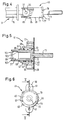
- a guide channel 17 is formed in the guide body, the cross section of which is essentially cruciform (FIG. 3).
- the outer contour of the sliding body 15 is essentially cruciform in its area intended for displacement.
- the guide channel 17 has a wider longitudinal slot 18 over its entire length and, correspondingly, the sliding body 15 has a wider cross arm.
- a flange 25 with a radially extending thread 27 is arranged on the circumference of the guide body 13.
- the sliding body 15 can be clamped or adjusted in a preferred position within the guide body 13 via a fastening screw 29 which can be screwed into the thread 27, and thus the length of the shift linkage can be determined.
- this has a first ball pin 31 with a first sword 33.
- the sliding body 15 also has a second ball pin 35 with a second sword 37 at the end section which protrudes from the solid body 13.
- these correspond to the first ball pin 31 and the first sword 33, the two swords 33, 37 being arranged perpendicular to one another when the sliding body 15 is inserted into the guide body 13.
- a switching unit 41 is fastened to a stove cover 39 in the region of a front cover of the gas stove (FIG. 5).
- This consists of three parts, namely a bearing body 43, a rotatable and rotatable rotating body 45 therein and a helical compression spring 47 arranged therebetween.
- the bearing body 43 is correspondingly equipped with a hollow cylinder with a substantially circular central opening 51, with a segmental stop on its inner peripheral wall 53 54 protrudes inward over the entire length of the central opening 51 and thereby forms a zero stop 55 and an end stop 57.
- two attachment lugs 59 are provided with a respective attachment opening 61 for attaching the bearing body 43 to the stove top 39.
- the rotating body 45 has a hollow cylindrical main body 71, from the closed end face 72 of which extends on the longitudinal axis of the rotating body 45 a rigidly connected cylindrical rotating body shaft 73 which is flattened in a partial region of the circumference.
- a switch button for operating the burning point can be plugged onto this (not shown).
- An annular shoulder 77 is formed on the end face 72 and serves as a stop for the compression spring 47.
- a radially extending extension 79 protrudes from the shoulder 77 and, in the assembled state of the switching unit 41, limits the range of rotation of the rotating body 45 in the bearing body 43 via the zero stop 55 and the end stop 57 of the bearing body 43 to 210 ° in accordance with the rotating range of the gas tap 1.
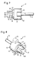
- a hook-shaped nose 83 is formed on an outer peripheral wall 81 of the main body in the longitudinal direction thereof.
- the nose 83 has a nose stop surface 84 which engages behind a stop end surface 85 of the stop ring 63 in the assembled state of the switching unit 41.
- a run-up slope 87 extending in the axial direction is formed immediately adjacent to the interruption 67.
- the rear side 88 thereof represents the extension of the inner wall of the interruption 67, the run-up slope 87 starting from the rear side 88 again passing into the stop face 85 along a portion of the circumference of the stop ring 63.
- the compression spring 47 By fastening the switching unit 41 to the stove top 39, the compression spring 47 is biased between the shoulder 77 of the rotating body 45 and the stop shoulder 65 of the stop ring 63 in the pressure direction and presses the rotating body 45 against the stove top 39. This is the zero position (not shown) Nose 83 pushed completely through the interruption 67 of the stop ring 63 in the direction of the stove interior. Rotation of the rotating body 45, starting from the zero stop 55 in the direction of the end stop 57, is initially prevented, however, by the rear side 88 of the run-up slope 87, which immediately adjoins the interruption 67 and protrudes in the axial direction of the bearing body 43 from the stop face 85.
- the nose 83 moves outside the effective range of the rear side 88 of the run-up slope 87 serving as a stop and can be turned in the direction of the end stop 57 become.
- the rotating body 45 runs with the Nose stop surface 84 of the nose 83 on the stop end face 85 of the stop ring 63 as a result of the spring force of the compression spring 47 if the operator does not use any axial force (FIG. 7).
- the range of rotation of the switching unit 41 is limited by the attachment of the attachment 79 to the end stop 57 corresponding to the range of rotation of the gas tap 1.
- a further turning of the rotating body 45 or the handle non-rotatably fastened to it is thereby excluded. Since the segment 54 in the form of a segment of a circle extends inside the bearing body 43 over its entire length, the attachment 79, regardless of how far the rotating body 45 is pressed into the bearing body 43, cannot be moved past either the zero stop 55 or the end stop 57.
- the indentation of the rotating body 45 or the ignition path of the switching unit 41 is limited by the shoulder 77 of the rotating body 45 striking the stop shoulder 65 of the bearing body 43 or the compressed compression spring 47.
- the rotating body 45 has on the sleeve-shaped end section facing the shift linkage 11 or the main body 71 a blind hole-shaped hollow cylinder 89 with a second sleeve slot 91, which together with the second ball pin 35 and the second sword 37 of the shift linkage 11 form a further ball joint coupling.
- the slot width in the region of the two wall interruptions of the hollow cylinder 89 forming the second slot 91 corresponds to the different strengths of a first partial sword 97 and a second partial sword 99 of the second sword 37 different sized.
- the first sleeve slot 9 of the joint body 3 described above is shaped corresponding to the second sleeve slot 91.
- an inner circumferential wall 100 of the hollow cylinder 89 of the rotating body 45 for the purpose of supporting the second ball pin 35 in a bearing is as large as its outer diameter over a certain length (FIG. 5). This length is limited on the one hand by an inwardly projecting locking shoulder 101 formed in the inner peripheral wall 100 and on the other hand by a spherical shell-shaped end stop 103 which extends radially inward from the inner peripheral wall 100.
- the second ball pin 35 which is locked in the correct position in the hollow cylinder 89, can be displaced in the longitudinal direction by approximately 3 mm between the spherical shell-shaped end stop 103 and the locking shoulder 101 at the inlet opening of the hollow cylinder 89 in accordance with a ball joint coupling with a length compensation play.
Landscapes
- Engineering & Computer Science (AREA)
- General Engineering & Computer Science (AREA)
- Physics & Mathematics (AREA)
- Mechanical Engineering (AREA)
- Fluid Mechanics (AREA)
- Combustion & Propulsion (AREA)
- Chemical & Material Sciences (AREA)
- General Physics & Mathematics (AREA)
- Automation & Control Theory (AREA)
- Taps Or Cocks (AREA)
- Air Bags (AREA)
- Domestic Plumbing Installations (AREA)
- Rotary Switch, Piano Key Switch, And Lever Switch (AREA)
Applications Claiming Priority (2)
| Application Number | Priority Date | Filing Date | Title |
|---|---|---|---|
| DE9420804U | 1994-12-23 | ||
| DE9420804U DE9420804U1 (de) | 1994-12-23 | 1994-12-23 | Gasherd mit Schalteinheit |
Publications (3)
| Publication Number | Publication Date |
|---|---|
| EP0718745A2 true EP0718745A2 (fr) | 1996-06-26 |
| EP0718745A3 EP0718745A3 (fr) | 1997-01-02 |
| EP0718745B1 EP0718745B1 (fr) | 2000-04-12 |
Family
ID=6917984
Family Applications (1)
| Application Number | Title | Priority Date | Filing Date |
|---|---|---|---|
| EP95118380A Expired - Lifetime EP0718745B1 (fr) | 1994-12-23 | 1995-11-22 | Cuisinière à gaz avec unité de commutation |
Country Status (3)
| Country | Link |
|---|---|
| EP (1) | EP0718745B1 (fr) |
| DE (2) | DE9420804U1 (fr) |
| ES (1) | ES2147254T3 (fr) |
Cited By (6)
| Publication number | Priority date | Publication date | Assignee | Title |
|---|---|---|---|---|
| DE19829286A1 (de) * | 1998-06-30 | 2000-01-05 | Bsh Bosch Siemens Hausgeraete | Gasherd |
| EP1083388A1 (fr) | 1999-09-07 | 2001-03-14 | BSH Bosch und Siemens Hausgeräte GmbH | Tringlerie télescopique pour des appareils de ménage |
| EP1167883A2 (fr) | 2000-06-28 | 2002-01-02 | BSH Bosch und Siemens Hausgeräte GmbH | Système d'actionnement d'allumage pour appareil de cuisson à gaz |
| EP1255082A3 (fr) * | 2001-04-27 | 2004-03-03 | BSH Fabricacion, S.A. | Unité de commutation avec un interrupteur rotatif et à pression |
| EP1278015A3 (fr) * | 2001-07-18 | 2004-09-01 | Miglio Emilio S.R.L. | Un appareil de contrôle pour contrôler des robinets d'impléments de cuisson |
| WO2022066117A3 (fr) * | 2020-09-23 | 2022-05-27 | Termal Elektronik Ve Devre Elemanlari Sanayi Ticaret Anonim Sirketi | Système de commutation rotatif pour appareils à combustion de gaz |
Family Cites Families (3)
| Publication number | Priority date | Publication date | Assignee | Title |
|---|---|---|---|---|
| DE2334243A1 (de) * | 1973-07-05 | 1975-01-23 | Karl Hehl | Bedienungseinrichtung, insbesondere fuer ein drosselventil an einer spritzgiessmaschine |
| DE3412517A1 (de) * | 1984-04-04 | 1985-10-17 | Klöckner-Moeller Elektrizitäts GmbH, 5300 Bonn | Befehlstaste mit drehantrieb |
| ES2013374A6 (es) * | 1988-12-07 | 1990-05-01 | Balay Sa | Accionador para mandos de aparatos domesticos empotrables. |
-
1994
- 1994-12-23 DE DE9420804U patent/DE9420804U1/de not_active Expired - Lifetime
-
1995
- 1995-11-22 ES ES95118380T patent/ES2147254T3/es not_active Expired - Lifetime
- 1995-11-22 EP EP95118380A patent/EP0718745B1/fr not_active Expired - Lifetime
- 1995-11-22 DE DE59508173T patent/DE59508173D1/de not_active Expired - Lifetime
Non-Patent Citations (1)
| Title |
|---|
| None |
Cited By (10)
| Publication number | Priority date | Publication date | Assignee | Title |
|---|---|---|---|---|
| DE19829286A1 (de) * | 1998-06-30 | 2000-01-05 | Bsh Bosch Siemens Hausgeraete | Gasherd |
| DE19829286B4 (de) * | 1998-06-30 | 2012-03-15 | BSH Bosch und Siemens Hausgeräte GmbH | Gasherd |
| EP1083388A1 (fr) | 1999-09-07 | 2001-03-14 | BSH Bosch und Siemens Hausgeräte GmbH | Tringlerie télescopique pour des appareils de ménage |
| WO2001018454A1 (fr) | 1999-09-07 | 2001-03-15 | BSH Bosch und Siemens Hausgeräte GmbH | Tige telescopique pour appareils menagers |
| US6715483B2 (en) | 1999-09-07 | 2004-04-06 | Bsh Bosch Und Siemens Hausgeraete Gmbh | Telescopic linkage for household appliances |
| EP1167883A2 (fr) | 2000-06-28 | 2002-01-02 | BSH Bosch und Siemens Hausgeräte GmbH | Système d'actionnement d'allumage pour appareil de cuisson à gaz |
| EP1167883A3 (fr) * | 2000-06-28 | 2012-01-18 | BSH Bosch und Siemens Hausgeräte GmbH | Système d'actionnement d'allumage pour appareil de cuisson à gaz |
| EP1255082A3 (fr) * | 2001-04-27 | 2004-03-03 | BSH Fabricacion, S.A. | Unité de commutation avec un interrupteur rotatif et à pression |
| EP1278015A3 (fr) * | 2001-07-18 | 2004-09-01 | Miglio Emilio S.R.L. | Un appareil de contrôle pour contrôler des robinets d'impléments de cuisson |
| WO2022066117A3 (fr) * | 2020-09-23 | 2022-05-27 | Termal Elektronik Ve Devre Elemanlari Sanayi Ticaret Anonim Sirketi | Système de commutation rotatif pour appareils à combustion de gaz |
Also Published As
| Publication number | Publication date |
|---|---|
| DE9420804U1 (de) | 1995-02-16 |
| EP0718745B1 (fr) | 2000-04-12 |
| EP0718745A3 (fr) | 1997-01-02 |
| DE59508173D1 (de) | 2000-05-18 |
| ES2147254T3 (es) | 2000-09-01 |
Similar Documents
| Publication | Publication Date | Title |
|---|---|---|
| DE10309921A1 (de) | Stuhl, insbesondere Bürostuhl | |
| EP0733747A2 (fr) | Support de pomme de douche | |
| CH708307B1 (de) | Tragbarer Zeitmesser und Verfahren zur Herstellung der Krone des Zeitmessers. | |
| EP0604793A1 (fr) | Applicateur avec une mine en matériau pâteux | |
| DE3432183A1 (de) | Manuelle einstellvorrichtung fuer schwenkbare aussenspiegel u.dgl. | |
| DE10044448C1 (de) | Drehschalteranordnung für ein Haushaltsgerät | |
| EP0718745B1 (fr) | Cuisinière à gaz avec unité de commutation | |
| EP0683931B1 (fr) | Appareil de commande et/ou de signalisation | |
| EP0964493A2 (fr) | Entrée de câble de forme angulaire avec une lieu de séparation entre les deux branches | |
| DE3300623A1 (de) | Ventil, insbesondere thermostatventil fuer warmwasserheizkoerper | |
| DE102005032509A1 (de) | Bedienelement | |
| EP1083388B1 (fr) | Tringlerie télescopique pour des appareils de ménage | |
| EP0496103B1 (fr) | Soupape sanitaire avec sortie orientable | |
| EP0817704A1 (fr) | Mandrin muni d'un systeme d'accouplement | |
| DE19832089A1 (de) | Drehschalter für Haushaltsgeräte | |
| EP0836959B1 (fr) | Dispositif d'émergence pour l'actionnement d'un toit coulissant | |
| EP1318534B1 (fr) | Fixation pour un axe de une bouton rotatif et escamotable | |
| EP3486407A1 (fr) | Élément de poignée et garniture de poignée de fenêtre | |
| DE19829286A1 (de) | Gasherd | |
| DE3518661A1 (de) | Schraubenschluessel | |
| EP4001555A1 (fr) | Poignée de commande avec conducteur de longueur variable | |
| DE69803126T2 (de) | Kraftfahrzeugscheinwerfer mit Einstellung der Orientierung des Lichtbündels | |
| DE202019107045U1 (de) | Linearantrieb mit einfach montierbarem Elektromotor | |
| EP4628769A1 (fr) | Dispositif de poignée de commande pour une soupape thermostatique et dispositif de montage mural | |
| EP0966588A1 (fr) | Dispositif comportant un element mobile |
Legal Events
| Date | Code | Title | Description |
|---|---|---|---|
| PUAI | Public reference made under article 153(3) epc to a published international application that has entered the european phase |
Free format text: ORIGINAL CODE: 0009012 |
|
| AK | Designated contracting states |
Kind code of ref document: A2 Designated state(s): DE ES FR GB IT NL |
|
| PUAL | Search report despatched |
Free format text: ORIGINAL CODE: 0009013 |
|
| AK | Designated contracting states |
Kind code of ref document: A3 Designated state(s): DE ES FR GB IT NL |
|
| 17P | Request for examination filed |
Effective date: 19970604 |
|
| RAP1 | Party data changed (applicant data changed or rights of an application transferred) |
Owner name: BSH BOSCH UND SIEMENS HAUSGERAETE GMBH |
|
| GRAG | Despatch of communication of intention to grant |
Free format text: ORIGINAL CODE: EPIDOS AGRA |
|
| 17Q | First examination report despatched |
Effective date: 19990430 |
|
| GRAG | Despatch of communication of intention to grant |
Free format text: ORIGINAL CODE: EPIDOS AGRA |
|
| GRAH | Despatch of communication of intention to grant a patent |
Free format text: ORIGINAL CODE: EPIDOS IGRA |
|
| GRAH | Despatch of communication of intention to grant a patent |
Free format text: ORIGINAL CODE: EPIDOS IGRA |
|
| GRAA | (expected) grant |
Free format text: ORIGINAL CODE: 0009210 |
|
| AK | Designated contracting states |
Kind code of ref document: B1 Designated state(s): DE ES FR GB IT NL |
|
| GBT | Gb: translation of ep patent filed (gb section 77(6)(a)/1977) |
Effective date: 20000413 |
|
| REF | Corresponds to: |
Ref document number: 59508173 Country of ref document: DE Date of ref document: 20000518 |
|
| ET | Fr: translation filed | ||
| ITF | It: translation for a ep patent filed | ||
| REG | Reference to a national code |
Ref country code: ES Ref legal event code: FG2A Ref document number: 2147254 Country of ref document: ES Kind code of ref document: T3 |
|
| PLBE | No opposition filed within time limit |
Free format text: ORIGINAL CODE: 0009261 |
|
| STAA | Information on the status of an ep patent application or granted ep patent |
Free format text: STATUS: NO OPPOSITION FILED WITHIN TIME LIMIT |
|
| 26N | No opposition filed | ||
| PGFP | Annual fee paid to national office [announced via postgrant information from national office to epo] |
Ref country code: NL Payment date: 20011128 Year of fee payment: 7 |
|
| REG | Reference to a national code |
Ref country code: GB Ref legal event code: IF02 |
|
| PG25 | Lapsed in a contracting state [announced via postgrant information from national office to epo] |
Ref country code: NL Free format text: LAPSE BECAUSE OF NON-PAYMENT OF DUE FEES Effective date: 20030601 |
|
| NLV4 | Nl: lapsed or anulled due to non-payment of the annual fee |
Effective date: 20030601 |
|
| PG25 | Lapsed in a contracting state [announced via postgrant information from national office to epo] |
Ref country code: IT Free format text: LAPSE BECAUSE OF NON-PAYMENT OF DUE FEES Effective date: 20051122 |
|
| PGFP | Annual fee paid to national office [announced via postgrant information from national office to epo] |
Ref country code: GB Payment date: 20141120 Year of fee payment: 20 Ref country code: ES Payment date: 20141120 Year of fee payment: 20 Ref country code: DE Payment date: 20141130 Year of fee payment: 20 |
|
| PGFP | Annual fee paid to national office [announced via postgrant information from national office to epo] |
Ref country code: FR Payment date: 20141118 Year of fee payment: 20 |
|
| REG | Reference to a national code |
Ref country code: DE Ref legal event code: R081 Ref document number: 59508173 Country of ref document: DE Owner name: BSH HAUSGERAETE GMBH, DE Free format text: FORMER OWNER: BSH BOSCH UND SIEMENS HAUSGERAETE GMBH, 81739 MUENCHEN, DE Effective date: 20150408 |
|
| REG | Reference to a national code |
Ref country code: ES Ref legal event code: PC2A Owner name: BSH HAUSGERATE GMBH Effective date: 20150527 |
|
| REG | Reference to a national code |
Ref country code: DE Ref legal event code: R071 Ref document number: 59508173 Country of ref document: DE |
|
| REG | Reference to a national code |
Ref country code: GB Ref legal event code: PE20 Expiry date: 20151121 |
|
| PG25 | Lapsed in a contracting state [announced via postgrant information from national office to epo] |
Ref country code: GB Free format text: LAPSE BECAUSE OF EXPIRATION OF PROTECTION Effective date: 20151121 |
|
| REG | Reference to a national code |
Ref country code: ES Ref legal event code: FD2A Effective date: 20160229 |
|
| PG25 | Lapsed in a contracting state [announced via postgrant information from national office to epo] |
Ref country code: ES Free format text: LAPSE BECAUSE OF EXPIRATION OF PROTECTION Effective date: 20151123 |