EP0719662A2 - Bandage pneumatique - Google Patents
Bandage pneumatique Download PDFInfo
- Publication number
- EP0719662A2 EP0719662A2 EP95309513A EP95309513A EP0719662A2 EP 0719662 A2 EP0719662 A2 EP 0719662A2 EP 95309513 A EP95309513 A EP 95309513A EP 95309513 A EP95309513 A EP 95309513A EP 0719662 A2 EP0719662 A2 EP 0719662A2
- Authority
- EP
- European Patent Office
- Prior art keywords
- short fibre
- bead
- tyre
- carcass
- weight
- Prior art date
- Legal status (The legal status is an assumption and is not a legal conclusion. Google has not performed a legal analysis and makes no representation as to the accuracy of the status listed.)
- Granted
Links
- 239000000835 fiber Substances 0.000 claims abstract description 84
- 239000011324 bead Substances 0.000 claims abstract description 56
- 230000003014 reinforcing effect Effects 0.000 claims abstract description 37
- 229920001971 elastomer Polymers 0.000 claims abstract description 32
- 239000005060 rubber Substances 0.000 claims abstract description 32
- 150000001875 compounds Chemical class 0.000 claims abstract description 13
- 239000006229 carbon black Substances 0.000 claims abstract description 11
- ZCYVEMRRCGMTRW-UHFFFAOYSA-N 7553-56-2 Chemical compound [I] ZCYVEMRRCGMTRW-UHFFFAOYSA-N 0.000 claims abstract description 7
- 229910052740 iodine Inorganic materials 0.000 claims abstract description 7
- 239000011630 iodine Substances 0.000 claims abstract description 7
- 239000005062 Polybutadiene Substances 0.000 claims abstract description 6
- 244000043261 Hevea brasiliensis Species 0.000 claims abstract description 5
- 229920003052 natural elastomer Polymers 0.000 claims abstract description 5
- 229920001194 natural rubber Polymers 0.000 claims abstract description 5
- 229920002857 polybutadiene Polymers 0.000 claims abstract description 5
- 229920003049 isoprene rubber Polymers 0.000 claims abstract description 4
- 238000005096 rolling process Methods 0.000 description 30
- 230000003247 decreasing effect Effects 0.000 description 17
- 239000000203 mixture Substances 0.000 description 12
- 230000007423 decrease Effects 0.000 description 9
- 230000000694 effects Effects 0.000 description 6
- 230000020169 heat generation Effects 0.000 description 6
- 239000004677 Nylon Substances 0.000 description 4
- 229920001778 nylon Polymers 0.000 description 4
- 229920000271 Kevlar® Polymers 0.000 description 2
- 229920000297 Rayon Polymers 0.000 description 2
- 229910000831 Steel Inorganic materials 0.000 description 2
- 239000004760 aramid Substances 0.000 description 2
- 229920003235 aromatic polyamide Polymers 0.000 description 2
- 239000010426 asphalt Substances 0.000 description 2
- 230000002542 deteriorative effect Effects 0.000 description 2
- 239000000446 fuel Substances 0.000 description 2
- 239000004761 kevlar Substances 0.000 description 2
- 239000000463 material Substances 0.000 description 2
- 229920000728 polyester Polymers 0.000 description 2
- 239000002964 rayon Substances 0.000 description 2
- 239000010959 steel Substances 0.000 description 2
- 239000013585 weight reducing agent Substances 0.000 description 2
- OKTJSMMVPCPJKN-UHFFFAOYSA-N Carbon Chemical compound [C] OKTJSMMVPCPJKN-UHFFFAOYSA-N 0.000 description 1
- 229920000742 Cotton Polymers 0.000 description 1
- 229920001875 Ebonite Polymers 0.000 description 1
- 229920002978 Vinylon Polymers 0.000 description 1
- 239000003963 antioxidant agent Substances 0.000 description 1
- 230000003078 antioxidant effect Effects 0.000 description 1
- 230000009286 beneficial effect Effects 0.000 description 1
- 238000003490 calendering Methods 0.000 description 1
- 229910052799 carbon Inorganic materials 0.000 description 1
- 239000012461 cellulose resin Substances 0.000 description 1
- 238000002485 combustion reaction Methods 0.000 description 1
- 238000010276 construction Methods 0.000 description 1
- 238000011156 evaluation Methods 0.000 description 1
- 239000003365 glass fiber Substances 0.000 description 1
- 238000004519 manufacturing process Methods 0.000 description 1
- 239000002184 metal Substances 0.000 description 1
- 230000002787 reinforcement Effects 0.000 description 1
- 239000004575 stone Substances 0.000 description 1
- 239000000126 substance Substances 0.000 description 1
- 238000004381 surface treatment Methods 0.000 description 1
- 238000004073 vulcanization Methods 0.000 description 1
Images
Classifications
-
- B—PERFORMING OPERATIONS; TRANSPORTING
- B60—VEHICLES IN GENERAL
- B60C—VEHICLE TYRES; TYRE INFLATION; TYRE CHANGING; CONNECTING VALVES TO INFLATABLE ELASTIC BODIES IN GENERAL; DEVICES OR ARRANGEMENTS RELATED TO TYRES
- B60C9/00—Reinforcements or ply arrangement of pneumatic tyres
- B60C9/02—Carcasses
- B60C9/04—Carcasses the reinforcing cords of each carcass ply arranged in a substantially parallel relationship
- B60C9/08—Carcasses the reinforcing cords of each carcass ply arranged in a substantially parallel relationship the cords extend transversely from bead to bead, i.e. radial ply
- B60C9/09—Carcasses the reinforcing cords of each carcass ply arranged in a substantially parallel relationship the cords extend transversely from bead to bead, i.e. radial ply combined with other carcass plies having cords extending diagonally from bead to bead, i.e. combined radial ply and bias angle ply
-
- B—PERFORMING OPERATIONS; TRANSPORTING
- B60—VEHICLES IN GENERAL
- B60C—VEHICLE TYRES; TYRE INFLATION; TYRE CHANGING; CONNECTING VALVES TO INFLATABLE ELASTIC BODIES IN GENERAL; DEVICES OR ARRANGEMENTS RELATED TO TYRES
- B60C1/00—Tyres characterised by the chemical composition or the physical arrangement or mixture of the composition
- B60C1/0025—Compositions of the sidewalls
-
- B—PERFORMING OPERATIONS; TRANSPORTING
- B60—VEHICLES IN GENERAL
- B60C—VEHICLE TYRES; TYRE INFLATION; TYRE CHANGING; CONNECTING VALVES TO INFLATABLE ELASTIC BODIES IN GENERAL; DEVICES OR ARRANGEMENTS RELATED TO TYRES
- B60C13/00—Tyre sidewalls; Protecting, decorating, marking, or the like, thereof
-
- B—PERFORMING OPERATIONS; TRANSPORTING
- B60—VEHICLES IN GENERAL
- B60C—VEHICLE TYRES; TYRE INFLATION; TYRE CHANGING; CONNECTING VALVES TO INFLATABLE ELASTIC BODIES IN GENERAL; DEVICES OR ARRANGEMENTS RELATED TO TYRES
- B60C15/00—Tyre beads, e.g. ply turn-up or overlap
- B60C15/06—Flipper strips, fillers, or chafing strips and reinforcing layers for the construction of the bead
-
- B—PERFORMING OPERATIONS; TRANSPORTING
- B60—VEHICLES IN GENERAL
- B60C—VEHICLE TYRES; TYRE INFLATION; TYRE CHANGING; CONNECTING VALVES TO INFLATABLE ELASTIC BODIES IN GENERAL; DEVICES OR ARRANGEMENTS RELATED TO TYRES
- B60C9/00—Reinforcements or ply arrangement of pneumatic tyres
- B60C9/02—Carcasses
- B60C9/12—Carcasses built-up with rubberised layers of discrete fibres or filaments
-
- B—PERFORMING OPERATIONS; TRANSPORTING
- B60—VEHICLES IN GENERAL
- B60C—VEHICLE TYRES; TYRE INFLATION; TYRE CHANGING; CONNECTING VALVES TO INFLATABLE ELASTIC BODIES IN GENERAL; DEVICES OR ARRANGEMENTS RELATED TO TYRES
- B60C15/00—Tyre beads, e.g. ply turn-up or overlap
- B60C15/0009—Tyre beads, e.g. ply turn-up or overlap features of the carcass terminal portion
- B60C2015/009—Height of the carcass terminal portion defined in terms of a numerical value or ratio in proportion to section height
-
- B—PERFORMING OPERATIONS; TRANSPORTING
- B60—VEHICLES IN GENERAL
- B60C—VEHICLE TYRES; TYRE INFLATION; TYRE CHANGING; CONNECTING VALVES TO INFLATABLE ELASTIC BODIES IN GENERAL; DEVICES OR ARRANGEMENTS RELATED TO TYRES
- B60C15/00—Tyre beads, e.g. ply turn-up or overlap
- B60C15/06—Flipper strips, fillers, or chafing strips and reinforcing layers for the construction of the bead
- B60C15/0628—Flipper strips, fillers, or chafing strips and reinforcing layers for the construction of the bead comprising a bead reinforcing layer
- B60C2015/065—Flipper strips, fillers, or chafing strips and reinforcing layers for the construction of the bead comprising a bead reinforcing layer at the axially outer side of the carcass turn-up portion not wrapped around the bead core
-
- Y—GENERAL TAGGING OF NEW TECHNOLOGICAL DEVELOPMENTS; GENERAL TAGGING OF CROSS-SECTIONAL TECHNOLOGIES SPANNING OVER SEVERAL SECTIONS OF THE IPC; TECHNICAL SUBJECTS COVERED BY FORMER USPC CROSS-REFERENCE ART COLLECTIONS [XRACs] AND DIGESTS
- Y02—TECHNOLOGIES OR APPLICATIONS FOR MITIGATION OR ADAPTATION AGAINST CLIMATE CHANGE
- Y02T—CLIMATE CHANGE MITIGATION TECHNOLOGIES RELATED TO TRANSPORTATION
- Y02T10/00—Road transport of goods or passengers
- Y02T10/80—Technologies aiming to reduce greenhouse gasses emissions common to all road transportation technologies
- Y02T10/86—Optimisation of rolling resistance, e.g. weight reduction
-
- Y—GENERAL TAGGING OF NEW TECHNOLOGICAL DEVELOPMENTS; GENERAL TAGGING OF CROSS-SECTIONAL TECHNOLOGIES SPANNING OVER SEVERAL SECTIONS OF THE IPC; TECHNICAL SUBJECTS COVERED BY FORMER USPC CROSS-REFERENCE ART COLLECTIONS [XRACs] AND DIGESTS
- Y10—TECHNICAL SUBJECTS COVERED BY FORMER USPC
- Y10T—TECHNICAL SUBJECTS COVERED BY FORMER US CLASSIFICATION
- Y10T152/00—Resilient tires and wheels
- Y10T152/10—Tires, resilient
- Y10T152/10495—Pneumatic tire or inner tube
- Y10T152/10513—Tire reinforcement material characterized by short length fibers or the like
-
- Y—GENERAL TAGGING OF NEW TECHNOLOGICAL DEVELOPMENTS; GENERAL TAGGING OF CROSS-SECTIONAL TECHNOLOGIES SPANNING OVER SEVERAL SECTIONS OF THE IPC; TECHNICAL SUBJECTS COVERED BY FORMER USPC CROSS-REFERENCE ART COLLECTIONS [XRACs] AND DIGESTS
- Y10—TECHNICAL SUBJECTS COVERED BY FORMER USPC
- Y10T—TECHNICAL SUBJECTS COVERED BY FORMER US CLASSIFICATION
- Y10T152/00—Resilient tires and wheels
- Y10T152/10—Tires, resilient
- Y10T152/10495—Pneumatic tire or inner tube
- Y10T152/10819—Characterized by the structure of the bead portion of the tire
- Y10T152/10837—Bead characterized by the radial extent of apex, flipper or chafer into tire sidewall
-
- Y—GENERAL TAGGING OF NEW TECHNOLOGICAL DEVELOPMENTS; GENERAL TAGGING OF CROSS-SECTIONAL TECHNOLOGIES SPANNING OVER SEVERAL SECTIONS OF THE IPC; TECHNICAL SUBJECTS COVERED BY FORMER USPC CROSS-REFERENCE ART COLLECTIONS [XRACs] AND DIGESTS
- Y10—TECHNICAL SUBJECTS COVERED BY FORMER USPC
- Y10T—TECHNICAL SUBJECTS COVERED BY FORMER US CLASSIFICATION
- Y10T152/00—Resilient tires and wheels
- Y10T152/10—Tires, resilient
- Y10T152/10495—Pneumatic tire or inner tube
- Y10T152/10855—Characterized by the carcass, carcass material, or physical arrangement of the carcass materials
- Y10T152/10864—Sidewall stiffening or reinforcing means other than main carcass plies or foldups thereof about beads
Definitions
- the present invention relates to a pneumatic tyre, in which the rolling resistance is reduced without sacrificing steering stability and ride comfort.
- the rolling resistance thereof is decreased and the rolling resistance of the car is decreased.
- other tyre performances for example, steering stability, ride comfort and the like are greatly deteriorated.
- a pneumatic radial tyre which comprises a carcass having edge portions turned up one around each bead core from the axially inside to outside of the tyre and a bead apex extending radially outwardly from the bead core
- tyre rigidity decreases, and steering stability is greatly decreased.
- the present inventors devotedly studied how to greatly decrease rolling resistance without deteriorating steering stability and ride comfort of a pneumatic tyre which has a low-height carcass turnup portion and low-height bead apex and a low hysteresis loss tread rubber.
- an object of the present invention to provided such a pneumatic tyre, in which the rolling resistance is decreased without deteriorating the steering stability and ride comfort.
- a pneumatic tyre having an aspect ratio of not less than 60%, comprises a pair of bead cores disposed one in each bead portion, a carcass extending between the bead portions through a tread portion and sidewall portions and turned up around the bead cores to define a pair of turnup portions, a belt disposed radially outside the carcass in the tread portion and comprising belt plies of which the radially innermost ply has an axial width of from 0.8 to 1.2 times the tread width, a pair of bead apexes each tapering radially outwardly from each of the bead cores, characterised in that each of the carcass turnup portions has a radially outer end at a height of not more than 0.15 times the tyre section height H, measured from the bead base line, each of the bead apexes has a radially outer end at a height of not more than 0.25 times the tyre section height
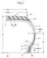
- Fig.1 is half a tyre meridian sectional view (a right half) of an embodiment of the present invention.
- a pneumatic tyre of the present invention comprises a tread portion 2, a pair of bead portions 4 each with a bead core 5 therein, a pair of sidewall portions 3 extending therebetween, a carcass 6 extending between the bead portions 4 through the tread portion 2 and sidewall portions 3, a belt 7 disposed radially outside the carcass 6 in the tread portion 2, and a bead apex 9 disposed in each bead portion and tapering radially outwardly from the bead core 5.
- the carcass 6 comprises at least one ply of cords arranged radially at an angle of from 90 to 65 degrees to the tyre equator C, which ply is turned up around the bead cores 5 in the bead portions from the inside to outside of the tyre to have a pair of turnup portions 6b and one main portion therebetween.
- the carcass 6 consists of a single ply 6A.
- organic fibre cords e.g. nylon, rayon, polyester, aromatic polyamide and the like and inorganic cords, e.g. steel and the like can be used.
- organic fibre cords are preferably used in view of a tyre weight reduction.
- the height Hc of the radially outer end X1 of the turnup portions 6b from the bead base line BL is not more than 0.15 times, preferably 0.12 to 0.15 times the tyre section height H so as to have a so called low turnup (LTU) carcass structure.
- the belt 7 comprises at least two plies having their cords crossed, a radially inner ply 7A and a radially outer ply 7B disposed radially outside thereof.
- each ply 7A, 7B are laid at a small angle of not more than 30 degrees, preferably not more than 20 degrees with respect to the tyre equator to provide a hoop effect on the carcass 6 and to reinforce the tread portion.
- the inner ply 7A is wider than the outer ply 7B, and the axial width BW of the innermost ply 7A is in the range of from 0.8 to 1.2 times the tread width TW.
- the bead apex 9 is made of a hard rubber compound having a JIS A hardness of from 65 to 95 degrees.
- the bead apex is disposed axially between each turnup portion and the main portion of the carcass and tapers radially outwardly from the bead apex.
- the radially outer end 9A of the bead apex 9 is preferably disposed at a height Hb of not more than 0.25 times, preferably 0.20 to 0.25 times the tyre section height H, each measured from the bead base line BL.
- the tyre aspect ratio is set in the range of more than 60%.
- a tread rubber 10 is disposed on the radially outer side of the belt in the tread portion to define the ground contacting surface thereof.
- the loss tangent of the tread rubber is usually about 0.18 to 0.28, but in the present invention, the loss tangent is set in a lower range of not more than 0.14, but not less than 0.07.
- the loss tangent is more than 0.14, the internal friction of the rubber tends to increase, and the special tread portion does not decrease the rolling resistance. If the loss tangent is less than 0.07, the wear resistance decreases.
- a short fibre reinforcing layer 11 is provided.
- the short fibre reinforcing layer 11 is disposed within a region Y in each sidewall portion between the radially outer end X1 of the carcass turnup portion 6b and the belt edge X2 which is the axial outer edge X2 of the radially innermost belt ply 7A in this example.
- the short fibre reinforcing layer 11 extends continuously in the tyre circumferential direction along the axially outer surface of the carcass 6.
- the short fibre reinforcing layer is made of a rubber compound including a base rubber, carbon black, short fibre and the like.
- the base rubber is a mixture of 40 to 70 parts by weight of butadiene rubber and 60 to 30 parts by weight of (natural rubber and/or isoprene rubber).
- organic fibre such as nylon, polyester, aramid, rayon, vinylon, cotton, cellulose resin, crystalline polybutadiene, and inorganic fibre such as metal fibre, glass fibre and the like can be used.
- fibre of a mixture or plurality of different materials as well as fibre of a single material.
- the short fibre content amounts to 10 to 30, preferably 10 to 20 parts by weight with respect to 100 parts by weight of the base rubber.
- the short fibre content is less than 10 parts by weight, the tyre circumferential rigidity can not be maintained, and there is no effect on improving the steering stability.
- the rigidity unfavourably increases, and ride comfort is deteriorated.
- the average length (L) of the short fibre is in the range of not less than 20 micron, preferably 50 to 1000 micron.
- the ratio (L/D) of the fibre length (L) to the fibre diameter (D) is in a range of not less than 100, more preferably, 200 to 2000.
- the rubber is not provided with a sufficient strength by the orientation of the short fibre described hereinafter.
- the ratio (E*a/E*b) of the complex elastic modulus E*a to the complex elastic modulus E*b of the short fibre reinforcing layer 11 is set in the range of not less than 5, preferably, 7 to 20, wherein, the complex elastic modulus E*a is that in the orientation direction of the short fibre, that is, the tyre circumferential direction.
- the complex elastic modulus E*b is that in the direction perpendicular to the orientation direction, that is, the tyre radial direction.
- the thickness of the short fibre reinforcing layer is set in the range of from 0.3 to 1.0 mm, preferably 0.5 to 1.0 mm.
- the thickness exceeds 1.0 mm, the rigidity difference between the fibre oriented direction and the direction perpendicular to it decreases. As a result, the improvement in the steering stability is decreased, and the rolling resistance and tyre weight increase. If the thickness is less than 0.3 mm, the production is difficult.
- a black having an iodine number of from 30 to 90 mg/g is preferably used.
- HAF(82), FEF(43), GPF(36) and the like provided by Showa Cabot company, Mitsubishi chemical company, Tokai carbon company etc., can be used.
- the iodine number is less than 30 mg/g, the reinforcement to the rubber is low and the rubber decreases in strength and cut resistance. If the iodine number is more than 90 mg/g, the rubber increases in heat generation, and the tyre rolling resistance increases.
- the carbon black content is in the range of not more than 30 parts by weight, preferably, 10 to 25 parts by weight.
- the content of the carbon black which generally increases the rigidity and heat generation of the rubber can be decreased, because the tyre circumferential rigidity can be increased by the oriented short fibre.
- the balance between the rolling resistance and steering stability is improved, and a tyre weight reduction can be achieved.
- oil, antioxidant, wax, vulcanisation accelerator and the like are added to the rubber compound.
- a sheet of rubber for forming the short fibre reinforcing layer in which at least 90% of short fibre is oriented in the specified direction is manufactured.
- the short fibre reinforcing layer is preferably disposed in a region between the radially outer end of the bead apex 9 and the maximum tyre section width point M to achieve both the steering stability and ride comfort.
- the radially inner end of the short fibre reinforcing layer 11 is disposed at the substantially same height H1 as the height Hb of the radially outer edge 9A of the bead apex 9.
- the radially outer end is disposed at the substantially same height H2 as that of the maximum tyre sectional width point M.
- the short fibre reinforcing layer 11 extends from the position X1 to the position X2.
- the above-mentioned loss tangent and complex elastic modulus were measured with a viscoelasticity spectrometer (VESF-III model) made by Iwamotoseisakusyo Co., Ltd.
- the measuring conditions were as follows: temperature of 70 degrees C, frequency of 10Hz, initial strain of 10%, dynamic distortion of +-1%.
- compositions 1 to 5 shown in Table 1 short fibre reinforcing layers were made by means of extruding.
- the short fibre A and B in Table 1 were Kevlar short fibre and nylon short fibre, respectively.
- the short fibre A, B was mixed with natural rubber NR at the specified percentage in advance.
- NR in Table 1 indicates the total of NR included in the rubber compound.
- the iodine number of carbon black was 43 mg/g. Only the compositions 1 and 2 satisfied the limitations of the present invention.
- Table 1 (parts by weight ) Composition 1 2 3 4 5 NR 45 45 45 45 70 BR 55 55 55 55 30 Short fibre A *1 15 5 15 Short fibre B *2 15 35 Carbon black 20 20 20 40 10 *1 Kevlar short fibre (M/B 6F722 Du Point) *2 Nylon short fibre (HE-0100 Ube Industries)
- a tyre according to the present invention (EX.1) whose tyre size was 205/65R15 and which had the construction shown Fig.1 was experimentally made. Also reference tyres (Ref.1 and 2) having no short fibre reinforcing layer were made. Each tyre was tested for rolling resistance, steering stability and ride comfort as follows.
- Each tyre was mounted on a 6JJx15 rim, and the rolling resistance was measured with a rolling resistance tester under an inner pressure of 2.0 kg/sq.cm, a speed of 80 km/h and a load of 400 kgf.
- the resistance is indicated by an index based on the reference tyre 1 being set at 100. The smaller the index, the better the performance.
- test car (a 3000cc FF car) provided on the four wheels with test tyres was run on a dry asphalt road surface on a test course, and the handling response, rigidity impression, grip and the like were evaluated by a skilled driver's feeling. The results are indicated by an index based on the reference tyre 1 being set at 100. The larger the index, the better the stability.
- Table 4 shows the results of an evaluation test when the short fibre reinforcing layer is outside the limitations of the present invention.
- Table 4 Tyre Ex. 3 Ref. 4 Ref. 5 Ref. 6 Ref. 7
- Short fibre reinforcing layer Composition 1 1 3 4 5 Thickness (mm) 1.5 0.7 0.7 0.7 0.7 Fibre orientation *3 C R C C C E*a/E*b 4.8 12.3 2.1 11.6 10.1
- Rolling resistance 98 90 90 99 99
- Steering stability 96 95 98 106 102
- R oriented in tyre radial direction
- the rolling resistance is greatly reduced without sacrificing steering stability and ride comfort.
Landscapes
- Engineering & Computer Science (AREA)
- Mechanical Engineering (AREA)
- Tires In General (AREA)
- Compositions Of Macromolecular Compounds (AREA)
Applications Claiming Priority (3)
| Application Number | Priority Date | Filing Date | Title |
|---|---|---|---|
| JP6338575A JP2788715B2 (ja) | 1994-12-27 | 1994-12-27 | 空気入りタイヤ |
| JP33857594 | 1994-12-27 | ||
| JP338575/94 | 1994-12-27 |
Publications (3)
| Publication Number | Publication Date |
|---|---|
| EP0719662A2 true EP0719662A2 (fr) | 1996-07-03 |
| EP0719662A3 EP0719662A3 (fr) | 1997-04-02 |
| EP0719662B1 EP0719662B1 (fr) | 1999-08-11 |
Family
ID=18319469
Family Applications (1)
| Application Number | Title | Priority Date | Filing Date |
|---|---|---|---|
| EP95309513A Expired - Lifetime EP0719662B1 (fr) | 1994-12-27 | 1995-12-28 | Bandage pneumatique |
Country Status (4)
| Country | Link |
|---|---|
| US (1) | US5707462A (fr) |
| EP (1) | EP0719662B1 (fr) |
| JP (1) | JP2788715B2 (fr) |
| DE (1) | DE69511367T2 (fr) |
Cited By (8)
| Publication number | Priority date | Publication date | Assignee | Title |
|---|---|---|---|---|
| EP1000972A1 (fr) * | 1998-11-13 | 2000-05-17 | Bridgestone Corporation | Composition de caoutchouc renforcée de fibres courtes et son utilisation dans un pneu radial |
| US6415840B1 (en) * | 1997-05-26 | 2002-07-09 | Bridgestone Corporation | Pneumatic safety tire with rubber-organic filament fiber layer |
| EP1640185A1 (fr) * | 2004-09-23 | 2006-03-29 | The Goodyear Tire & Rubber Company | Pneumatique avec un flanc résistant |
| EP1803586A1 (fr) * | 2005-12-22 | 2007-07-04 | The Goodyear Tire & Rubber Company | Pneu |
| EP2061663A4 (fr) * | 2006-08-31 | 2010-12-22 | Michelin Soc Tech | Composition élastomère possédant des microfibres de verre |
| EP3009279A1 (fr) * | 2014-10-14 | 2016-04-20 | Sumitomo Rubber Industries, Ltd. | Pneumatique |
| CN109835123A (zh) * | 2019-01-29 | 2019-06-04 | 安徽佳通乘用子午线轮胎有限公司 | 一种降低滚动阻力的充气轮胎 |
| CN111163948A (zh) * | 2017-10-02 | 2020-05-15 | 米其林集团总公司 | 具有增强的下部区域的轮胎 |
Families Citing this family (25)
| Publication number | Priority date | Publication date | Assignee | Title |
|---|---|---|---|---|
| US6695025B1 (en) | 1999-05-18 | 2004-02-24 | The Goodyear Tire & Rubber Company | Runflat tire construction with ply cords having a variable modulus of elasticity |
| JP3459800B2 (ja) * | 1999-11-12 | 2003-10-27 | 住友ゴム工業株式会社 | 空気入りタイヤ |
| JP4681156B2 (ja) * | 2001-07-04 | 2011-05-11 | 住友ゴム工業株式会社 | 空気入りタイヤ |
| JP4672216B2 (ja) * | 2001-08-31 | 2011-04-20 | 住友ゴム工業株式会社 | 空気入りタイヤ |
| US20060041071A1 (en) * | 2004-08-19 | 2006-02-23 | Sandstrom Paul H | Pneumatic tire having a rubber component containing polyethylene terpolymer |
| JP4904028B2 (ja) * | 2005-08-11 | 2012-03-28 | 住友ゴム工業株式会社 | 空気入りタイヤ |
| WO2007129580A1 (fr) * | 2006-05-09 | 2007-11-15 | Sumitomo Rubber Industries, Ltd. | Pneu À roulage À plat |
| US7604031B2 (en) * | 2006-12-21 | 2009-10-20 | The Goodyear Tire & Rubber Company | Pneumatic tire |
| JP5017703B2 (ja) * | 2007-05-16 | 2012-09-05 | 住友ゴム工業株式会社 | ビードエイペックスおよびタイヤ |
| US20090156740A1 (en) * | 2007-12-15 | 2009-06-18 | Annette Lechtenboehmer | Tire with component containing polymeric nanofiber |
| JP4286319B1 (ja) * | 2008-02-01 | 2009-06-24 | 住友ゴム工業株式会社 | 空気入りタイヤ |
| JP5257185B2 (ja) * | 2008-05-19 | 2013-08-07 | 横浜ゴム株式会社 | 空気入りタイヤ |
| JP5280832B2 (ja) * | 2008-12-25 | 2013-09-04 | 住友ゴム工業株式会社 | 空気入りタイヤ |
| WO2012114743A1 (fr) | 2011-02-24 | 2012-08-30 | 株式会社ブリヂストン | Pneumatique à carcasse radiale |
| WO2012120826A1 (fr) | 2011-03-04 | 2012-09-13 | 株式会社ブリヂストン | Pneumatique |
| JP6672813B2 (ja) * | 2016-01-14 | 2020-03-25 | 横浜ゴム株式会社 | 空気入りタイヤ |
| RU2709151C1 (ru) * | 2016-10-06 | 2019-12-16 | Дзе Йокогама Раббер Ко., Лтд. | Шина с диагональным кордом |
| JP6779780B2 (ja) * | 2016-12-28 | 2020-11-04 | Toyo Tire株式会社 | 空気入りタイヤ |
| FR3090476A3 (fr) * | 2018-12-19 | 2020-06-26 | Michelin & Cie | Pneumatique pour camionnette optimisé |
| FR3090473A3 (fr) * | 2018-12-19 | 2020-06-26 | Michelin & Cie | Pneumatique pour camionnette optimisé |
| FR3090475A3 (fr) * | 2018-12-19 | 2020-06-26 | Michelin & Cie | Pneumatique pour camionnette optimisé |
| JP7368690B2 (ja) * | 2019-02-18 | 2023-10-25 | 横浜ゴム株式会社 | 空気入りタイヤ |
| JP7388056B2 (ja) * | 2019-08-29 | 2023-11-29 | 住友ゴム工業株式会社 | 空気入りタイヤ |
| FR3102091A1 (fr) * | 2019-10-22 | 2021-04-23 | Compagnie Generale Des Etablissements Michelin | Pneumatique à bande de roulement perfectionnée |
| JP7264008B2 (ja) * | 2019-10-23 | 2023-04-25 | 住友ゴム工業株式会社 | タイヤ |
Family Cites Families (11)
| Publication number | Priority date | Publication date | Assignee | Title |
|---|---|---|---|---|
| US3095027A (en) * | 1959-10-12 | 1963-06-25 | Firestone Tire & Rubber Co | Pneumatic tire |
| NL279924A (fr) * | 1961-06-28 | |||
| FR2261888B1 (fr) * | 1974-02-26 | 1976-12-10 | Kleber Colombes | |
| JPS63170109A (ja) * | 1986-12-29 | 1988-07-14 | Bridgestone Corp | 空気入りタイヤ |
| JP2664114B2 (ja) * | 1992-01-10 | 1997-10-15 | 住友ゴム工業株式会社 | 空気入りタイヤ |
| AU647984B2 (en) * | 1992-01-29 | 1994-03-31 | Bridgestone Corporation | Pneumatic radial tires |
| EP0581549B1 (fr) * | 1992-07-23 | 1996-01-24 | Sumitomo Rubber Industries Limited | Bandage pneumatique radial |
| DE4318825C1 (de) * | 1993-06-07 | 1994-06-09 | Continental Ag | Fahrzeugluftreifen |
| AT401367B (de) * | 1993-11-08 | 1996-08-26 | Semperit Ag | Radialluftreifen für pkw |
| JP3706181B2 (ja) * | 1994-12-09 | 2005-10-12 | 株式会社ブリヂストン | 空気入りラジアルタイヤ |
| US5538063A (en) * | 1994-12-23 | 1996-07-23 | The Goodyear Tire & Rubber Company | Aircraft tire with reinforcement insert |
-
1994
- 1994-12-27 JP JP6338575A patent/JP2788715B2/ja not_active Expired - Fee Related
-
1995
- 1995-12-27 US US08/579,142 patent/US5707462A/en not_active Expired - Fee Related
- 1995-12-28 DE DE69511367T patent/DE69511367T2/de not_active Expired - Fee Related
- 1995-12-28 EP EP95309513A patent/EP0719662B1/fr not_active Expired - Lifetime
Non-Patent Citations (1)
| Title |
|---|
| None |
Cited By (10)
| Publication number | Priority date | Publication date | Assignee | Title |
|---|---|---|---|---|
| US6415840B1 (en) * | 1997-05-26 | 2002-07-09 | Bridgestone Corporation | Pneumatic safety tire with rubber-organic filament fiber layer |
| EP1000972A1 (fr) * | 1998-11-13 | 2000-05-17 | Bridgestone Corporation | Composition de caoutchouc renforcée de fibres courtes et son utilisation dans un pneu radial |
| US6391971B1 (en) | 1998-11-13 | 2002-05-21 | Bridgestone Corporation | Short fiber-reinforced rubber composition and pneumatic radial tire using the same |
| EP1640185A1 (fr) * | 2004-09-23 | 2006-03-29 | The Goodyear Tire & Rubber Company | Pneumatique avec un flanc résistant |
| US7891394B2 (en) | 2004-09-23 | 2011-02-22 | The Goodyear Tire & Rubber Company | Tire with puncture resistant sidewall |
| EP1803586A1 (fr) * | 2005-12-22 | 2007-07-04 | The Goodyear Tire & Rubber Company | Pneu |
| EP2061663A4 (fr) * | 2006-08-31 | 2010-12-22 | Michelin Soc Tech | Composition élastomère possédant des microfibres de verre |
| EP3009279A1 (fr) * | 2014-10-14 | 2016-04-20 | Sumitomo Rubber Industries, Ltd. | Pneumatique |
| CN111163948A (zh) * | 2017-10-02 | 2020-05-15 | 米其林集团总公司 | 具有增强的下部区域的轮胎 |
| CN109835123A (zh) * | 2019-01-29 | 2019-06-04 | 安徽佳通乘用子午线轮胎有限公司 | 一种降低滚动阻力的充气轮胎 |
Also Published As
| Publication number | Publication date |
|---|---|
| EP0719662A3 (fr) | 1997-04-02 |
| EP0719662B1 (fr) | 1999-08-11 |
| JPH08175119A (ja) | 1996-07-09 |
| DE69511367D1 (de) | 1999-09-16 |
| DE69511367T2 (de) | 1999-11-25 |
| JP2788715B2 (ja) | 1998-08-20 |
| US5707462A (en) | 1998-01-13 |
Similar Documents
| Publication | Publication Date | Title |
|---|---|---|
| EP0719662B1 (fr) | Bandage pneumatique | |
| US5526863A (en) | Tire with reduced bead mass | |
| JP5216077B2 (ja) | 重荷重用空気入りタイヤ | |
| CA2220815C (fr) | Pneumatique | |
| AU724139B2 (en) | Light weight aramid belted radial tire | |
| US5388627A (en) | Pneumatic tire including a protective rubber layer on the outer surface of the sidewalls | |
| EP1867497A1 (fr) | Pneu a affaissement limite | |
| EP0844110A2 (fr) | Bandage pneumatique | |
| US7779878B2 (en) | Pneumatic tire | |
| EP0994783A1 (fr) | Pneu radial leger a ceinture en fibre de verre | |
| EP4371785B1 (fr) | Pneumatique radial pour avion | |
| CA2079522A1 (fr) | Pneu radial | |
| EP3305551B1 (fr) | Élément de renforcement pour pneumatique, et pneumatique mettant en uvre celui-ci | |
| EP0535938B1 (fr) | Bandage pneumatique radial | |
| EP1577122B1 (fr) | Pneumatique de roulage à plat | |
| JPWO1998056603A1 (ja) | 重荷重用空気入りラジアルタイヤ | |
| EP0413574A2 (fr) | Pneumatique radial pour grandes vitesses | |
| JP3079028B2 (ja) | 空気入りタイヤ | |
| EP2268492A1 (fr) | Pneu avec sommet comprenant une couche de mélange de caoutchouc à module très élevé | |
| JPH0228482B2 (fr) | ||
| JPH03169719A (ja) | 空気入りタイヤ | |
| JP3292410B2 (ja) | 空気入りタイヤ | |
| JPH06127206A (ja) | ニューマチック型ソリッドタイヤ | |
| JPH0796709A (ja) | 空気入りラジアルタイヤ | |
| HK1008737B (en) | Tire with reduced bead mass |
Legal Events
| Date | Code | Title | Description |
|---|---|---|---|
| PUAI | Public reference made under article 153(3) epc to a published international application that has entered the european phase |
Free format text: ORIGINAL CODE: 0009012 |
|
| AK | Designated contracting states |
Kind code of ref document: A2 Designated state(s): DE FR GB |
|
| PUAL | Search report despatched |
Free format text: ORIGINAL CODE: 0009013 |
|
| AK | Designated contracting states |
Kind code of ref document: A3 Designated state(s): DE FR GB |
|
| 17P | Request for examination filed |
Effective date: 19970425 |
|
| GRAG | Despatch of communication of intention to grant |
Free format text: ORIGINAL CODE: EPIDOS AGRA |
|
| 17Q | First examination report despatched |
Effective date: 19981117 |
|
| GRAG | Despatch of communication of intention to grant |
Free format text: ORIGINAL CODE: EPIDOS AGRA |
|
| GRAH | Despatch of communication of intention to grant a patent |
Free format text: ORIGINAL CODE: EPIDOS IGRA |
|
| GRAH | Despatch of communication of intention to grant a patent |
Free format text: ORIGINAL CODE: EPIDOS IGRA |
|
| GRAA | (expected) grant |
Free format text: ORIGINAL CODE: 0009210 |
|
| AK | Designated contracting states |
Kind code of ref document: B1 Designated state(s): DE FR GB |
|
| REF | Corresponds to: |
Ref document number: 69511367 Country of ref document: DE Date of ref document: 19990916 |
|
| ET | Fr: translation filed | ||
| PLBE | No opposition filed within time limit |
Free format text: ORIGINAL CODE: 0009261 |
|
| STAA | Information on the status of an ep patent application or granted ep patent |
Free format text: STATUS: NO OPPOSITION FILED WITHIN TIME LIMIT |
|
| 26N | No opposition filed | ||
| REG | Reference to a national code |
Ref country code: GB Ref legal event code: IF02 |
|
| PGFP | Annual fee paid to national office [announced via postgrant information from national office to epo] |
Ref country code: GB Payment date: 20071227 Year of fee payment: 13 Ref country code: FR Payment date: 20071210 Year of fee payment: 13 |
|
| PGFP | Annual fee paid to national office [announced via postgrant information from national office to epo] |
Ref country code: DE Payment date: 20071220 Year of fee payment: 13 |
|
| GBPC | Gb: european patent ceased through non-payment of renewal fee |
Effective date: 20081228 |
|
| REG | Reference to a national code |
Ref country code: FR Ref legal event code: ST Effective date: 20090831 |
|
| PG25 | Lapsed in a contracting state [announced via postgrant information from national office to epo] |
Ref country code: DE Free format text: LAPSE BECAUSE OF NON-PAYMENT OF DUE FEES Effective date: 20090701 |
|
| PG25 | Lapsed in a contracting state [announced via postgrant information from national office to epo] |
Ref country code: GB Free format text: LAPSE BECAUSE OF NON-PAYMENT OF DUE FEES Effective date: 20081228 |
|
| PG25 | Lapsed in a contracting state [announced via postgrant information from national office to epo] |
Ref country code: FR Free format text: LAPSE BECAUSE OF NON-PAYMENT OF DUE FEES Effective date: 20081231 |