EP0719902A1 - Elément de cloison mobile - Google Patents
Elément de cloison mobile Download PDFInfo
- Publication number
- EP0719902A1 EP0719902A1 EP95120220A EP95120220A EP0719902A1 EP 0719902 A1 EP0719902 A1 EP 0719902A1 EP 95120220 A EP95120220 A EP 95120220A EP 95120220 A EP95120220 A EP 95120220A EP 0719902 A1 EP0719902 A1 EP 0719902A1
- Authority
- EP
- European Patent Office
- Prior art keywords
- rollers
- pair
- partition element
- movable partition
- element according
- Prior art date
- Legal status (The legal status is an assumption and is not a legal conclusion. Google has not performed a legal analysis and makes no representation as to the accuracy of the status listed.)
- Granted
Links
- 238000005192 partition Methods 0.000 title claims description 29
- 238000010276 construction Methods 0.000 description 1
- 239000002184 metal Substances 0.000 description 1
- 230000000284 resting effect Effects 0.000 description 1
Images

Classifications
-
- E—FIXED CONSTRUCTIONS
- E04—BUILDING
- E04B—GENERAL BUILDING CONSTRUCTIONS; WALLS, e.g. PARTITIONS; ROOFS; FLOORS; CEILINGS; INSULATION OR OTHER PROTECTION OF BUILDINGS
- E04B2/00—Walls, e.g. partitions, for buildings; Wall construction with regard to insulation; Connections specially adapted to walls
- E04B2/74—Removable non-load-bearing partitions; Partitions with a free upper edge
- E04B2/82—Removable non-load-bearing partitions; Partitions with a free upper edge characterised by the manner in which edges are connected to the building; Means therefor; Special details of easily-removable partitions as far as related to the connection with other parts of the building
- E04B2/827—Partitions constituted of sliding panels
-
- E—FIXED CONSTRUCTIONS
- E05—LOCKS; KEYS; WINDOW OR DOOR FITTINGS; SAFES
- E05D—HINGES OR SUSPENSION DEVICES FOR DOORS, WINDOWS OR WINGS
- E05D15/00—Suspension arrangements for wings
- E05D15/06—Suspension arrangements for wings for wings sliding horizontally more or less in their own plane
- E05D15/0604—Suspension arrangements for wings for wings sliding horizontally more or less in their own plane allowing an additional movement
- E05D15/0608—Suspension arrangements for wings for wings sliding horizontally more or less in their own plane allowing an additional movement caused by track lay-out
-
- E—FIXED CONSTRUCTIONS
- E05—LOCKS; KEYS; WINDOW OR DOOR FITTINGS; SAFES
- E05Y—INDEXING SCHEME ASSOCIATED WITH SUBCLASSES E05D AND E05F, RELATING TO CONSTRUCTION ELEMENTS, ELECTRIC CONTROL, POWER SUPPLY, POWER SIGNAL OR TRANSMISSION, USER INTERFACES, MOUNTING OR COUPLING, DETAILS, ACCESSORIES, AUXILIARY OPERATIONS NOT OTHERWISE PROVIDED FOR, APPLICATION THEREOF
- E05Y2800/00—Details, accessories and auxiliary operations not otherwise provided for
-
- E—FIXED CONSTRUCTIONS
- E05—LOCKS; KEYS; WINDOW OR DOOR FITTINGS; SAFES
- E05Y—INDEXING SCHEME ASSOCIATED WITH SUBCLASSES E05D AND E05F, RELATING TO CONSTRUCTION ELEMENTS, ELECTRIC CONTROL, POWER SUPPLY, POWER SIGNAL OR TRANSMISSION, USER INTERFACES, MOUNTING OR COUPLING, DETAILS, ACCESSORIES, AUXILIARY OPERATIONS NOT OTHERWISE PROVIDED FOR, APPLICATION THEREOF
- E05Y2900/00—Application of doors, windows, wings or fittings thereof
- E05Y2900/10—Application of doors, windows, wings or fittings thereof for buildings or parts thereof
- E05Y2900/13—Type of wing
- E05Y2900/142—Partition walls
Definitions
- the invention relates to a movable partition element with a partition element sheet and at least one roller carriage, the rollers of which run on treads of a running rail on both sides of a longitudinal slot formed therein and on which the partition element sheet is suspended via at least one support element extending through the longitudinal slot of the running rail.
- the number and arrangement of the rollers of the roller carriage are such that when a branch of the running rail is run over, at least one roller always rests on a running surface on both sides of the longitudinal slot.
- the roller carriage preferably has a first and a second pair of rollers arranged on both sides of the longitudinal slot, the second pair of rollers, viewed in a first running direction of the roller carriage, lying in front of the first pair of rollers.
- the rollers of each pair are expediently arranged symmetrically to the longitudinal slot.
- the clear distance between the rollers of the second pair should correspond to the width of the longitudinal slot.
- the distance between the rollers of the first pair should be greater than that between the rollers of the second pair and should preferably be such that the rollers of the first pair run essentially along the outer sides of the treads of the running rail.
- the diameter of the rollers of the second pair can, for example, be smaller than the diameter of the rollers of the first pair.
- a further preferred embodiment is characterized in that the roller carriage has a third pair of rollers which are arranged on both sides of the longitudinal slot and which, viewed in the first running direction of the roller carriage, lie behind the first pair of rollers.
- the distance between the rollers of the third pair should essentially correspond to the distance between the rollers of the first pair, the distance between the rollers of the third pair being expediently such that they run essentially along the outside of the treads.
- the diameter of the rollers of the third pair can be smaller than the diameter of the rollers of the first pair for the reasons already mentioned.
- the diameter of the rollers of the third pair can be approximately the diameter of the rollers of the second pair.
- the supporting element should intersect a line connecting the pivot points of the rollers of the first pair of rollers.
- the rollers of each pair of rollers can lie on a common axis of rotation, the axis of rotation of each pair of rollers should be parallel to one another.
- the roller carriage can expediently be provided with at least one lateral guide roller, the axis of which is perpendicular and which touches a side wall of the travel rail, as a result of which the roller carriage can be guided precisely along the travel rail and in particular when passing through branches.
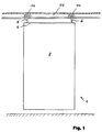
- the partition element 1 shown schematically in FIG. 1 comprises a partition element sheet 2, which usually consists of a metal frame and two cover plates fastened to it on both sides.
- a partition element sheet 2 On the top 4 of the partition element sheet 2 support bolts 6 are attached, which are still below Roller carriages 10 to be described in more detail are rotatably mounted.
- the roller carriages 10 run on the running surfaces of a running rail 50, also to be described in more detail below, which has a longitudinal central slot through which the support bolts 6 are guided, the running surfaces of the running rail 50 being provided on both sides of the central slot.
- Each partition element usually has two roller carriages 10, each with a support pin 6 rotatably mounted thereon.
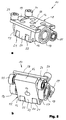
- a roller carriage 10 is shown in detail in FIGS. 2 and 3.
- the roller carriage 10 has a base body 12 which is provided with a through bore 14 for the rotatable mounting of the support bolt 6.
- a first roller 18 and 19 is rotatably mounted on each of the two sides 16 and 17 of the base body 12.
- the rollers 18 and 19, which are preferably ball-bearing or form the outer ring of a ball bearing (see in particular FIG. 3b), lie on a common axis and form a first pair of rollers.
- the bore 14 for the rotatable mounting of the support pin 6 is arranged so that its axis intersects the common axis of the first pair of rollers substantially perpendicularly, whereby the loads are essentially taken over by the first rollers 18, 19.
- two second rollers 21 and 22 are arranged at a distance from one another in the region of the front side 20 of the base body 12 in front of the first rollers 18 and 19.
- the rollers 21 and 22 lie on a common axis and form a second pair of rollers. Adjacent to the rear 24 of the base body 12 and in the viewing direction of FIG.
- a third roller 25 and 26 is rotatably mounted on the sides 16 and 17 of the base body 12, which is preferably also ball-bearing or one from the outer ring Ball bearing exists (see Figure 3b).
- the two rollers 25 and 26 lie on a common axis and form a third pair of rollers.
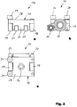
- the loads are essentially borne by the first rollers 18, 19, their diameter is clearly larger than that of the second and third rollers 21, 22 and 25, 26, which have essentially the same diameter.
- the distance between the rollers 25 and 26 of the third pair of rollers is approximately equal to the distance between the rollers 18 and 19 of the first pair of rollers, while the distance between the rollers 21 and 22 of the second pair of rollers is smaller.
- the distance between the outer sides of the rollers 21 and 22 facing the sides 16, 17 of the base body 12 is somewhat smaller than the clear distance between the inner sides of the first rollers 18 and 19 facing the base body 2.
- rollers of each pair of rollers are arranged symmetrically to an imaginary central axis running in the direction of rotation, which is also cut by the axis of the through bore 14 for the rotatable receiving of the support bolt.
- the second rollers 21 and 22, but also the first rollers 18 and 19 and the third rollers 25 and 26 protrude a little beyond the underside 23 of the base body 12.
- the axes of these rollers are each arranged, depending on their diameter, at such a height that the rollers lie with the underside of their circumference on a common plane which is formed by the running surface of the rail described below.
- two guide rollers 29 and 30 are rotatably mounted lying at a distance from one another in such a way that their axes are substantially perpendicular and at right angles to the horizontal axes of the rollers 18, 19, 21, 22, 25 and 26 run.
- the guide rollers 29 and 30 run in a guide groove provided in the guide rail, as a result of which the roller carriage is guided exactly in the desired direction of a branch.
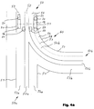
- FIG. 4 schematically shows a section of a travel rail 50 with a branch 60 in a top view. Furthermore, the position of the rollers 18, 19, 21, 22, 25 and 26 and the guide rollers 29, 30 of a roller carriage 10 of the type described above which can be moved along the travel rail 50 is indicated, with only the rollers and guide rollers being shown schematically for reasons of clarity while the remaining parts of the roller carriage described above are omitted. It should also be mentioned in this connection that, compared to the representations of FIGS. 2 and 3, the guide rollers 29, 30 are arranged on the opposite side 16 of the base body 12.
- the arrangement of the guide rollers 29, 30 is not limited to one of the two sides 16, 17 of the base body 12; rather, the arrangement of the guide rollers 29, 30 depends on which side of the running rail 50 a guide groove 55 is provided, in which the guide rollers 29, 30 engage and which will be discussed in more detail below.
- the travel rail 50 has a central slot 52 running along its central axis in the longitudinal direction, through which the supporting bolt 6 (see FIG. 1) extends, and flat horizontal running surfaces 53 and 54 formed on both sides of the central slot 52 which the rollers 18, 19, 21, 22, 25 and 26 rest on.
- the running surfaces 53 and 54 are bounded on the outside by side walls 51.
- the distances between the rollers of each pair of rollers selected in the previously described embodiment of the roller carriage 10 can be seen in relation to the dimensions of the running rail 50.
- the substantially equal distance between the rollers 18, 19 of the first pair of rollers and the rollers 25, 26 of the third pair of rollers is chosen so that the rollers 18, 19, 25 and 26 run adjacent to the side walls 51 delimiting the treads 53, 54; the distance between the outer sides of the rollers 18, 25 on the one hand and the rollers 19, 26 on the other hand and thus the width of the first and third pairs of rollers therefore corresponds approximately to the width of the running rail 50, but is slightly narrower.
- the clear distance between the inner sides of the rollers 21, 22 of the second pair of rollers corresponds to the width of the central slot 52, so that these two rollers 21, 22 run along both sides of the central slot 52.
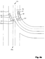
- the section of the travel rail 50 shown in FIG. 4a contains a branch 60, as a result of which the travel rail 50 is divided into a linearly extending first section 50a and a curved branching second section 50b. Accordingly, the first running surface 53 merges into the running surface 53a of the first running rail section 50a, while the second running surface 54 changes into the running surface 54b of the second running rail section 50b. With the branch 60, the central slot 52 also divides into the central slot 52a of the first rail section 50a and the central slot 52b of the second rail section 50b.
- a new second running surface 54a is formed in the first running rail section 50a, which is aligned with the second running surface 54, but is interrupted by the latter by the central slot 52b of the second running rail section 50b branching off from the central slot 52.
- a new first tread 53b is formed by the branch 56 in the second travel rail section 50b, which with the second Tread 54a of the first track section 50a has a common origin in the region of the junction 60, but is interrupted by the first tread 53 through the central slot 52a of the first track section 50a and limits the other side of the central slot 52b of the second track section 50b with respect to the second tread 54b.
- a guide groove 56 is provided in the area of the second running surface 54, which merges into the second running surface 54b of the branching-off second rail section 50b, which follows the arcuate course of the branched-off second rail section 50b.
- the guide groove 56 is arranged above the running surface 54 or 54b (for example on the upper side of a hollow profile forming the travel rail 50) and is delimited by two side walls 57 and 58, between which the guide rollers 29 and 30 of the roller carriage run.
- the described course of the guide groove 56 causes the roller carriage to be guided from the running rail 50 via the branch 56 into the branched-off second running rail section 50b.
- a guide groove can also be provided in the area of the first running surface 53 of the travel rail 50 and the adjoining first running surface 53a of the straight-forward first travel rail section 50a, so that roller carriages with guide rollers guided in such a guide groove go straight ahead into the first travel rail section via the branch 56 50a are forced to move.
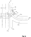
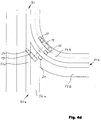
- FIGS. 4b to 4e it is shown schematically how the roller carriage described above is moved via the branch 56 into the branching arc-shaped second rail section 50b. For reasons of clarity, only the most important reference symbols are given in these figures.
- the first to third rollers 18, 22 and 25 are in constant contact with the second running surface 54 of the running rail 50 and the adjoining second running surface 54b of the branched second running rail section 50b.
- the first roller 19 crosses the central slot 52a of the first rail section 50a, but in addition to the rollers 18, 22 and 25 resting on the opposite second running surface 54 and 54b, the roller carriage is also replaced by the leading second one Roller 21, which already rests on the first running surface 53 of the branching-off second running rail section 50b, and by the trailing third running roller 26, which still rests on the first running surface 53 of the running rail 50.
- the roller carriage can be moved easily via a branch 56 without it falling into a central slot to be crossed and hooked there.
Landscapes
- Engineering & Computer Science (AREA)
- Architecture (AREA)
- Mechanical Engineering (AREA)
- Physics & Mathematics (AREA)
- Electromagnetism (AREA)
- Civil Engineering (AREA)
- Structural Engineering (AREA)
- Platform Screen Doors And Railroad Systems (AREA)
- Measuring Pulse, Heart Rate, Blood Pressure Or Blood Flow (AREA)
- Paper (AREA)
- Multiple-Way Valves (AREA)
- Prostheses (AREA)
- Surgical Instruments (AREA)
- Operating, Guiding And Securing Of Roll- Type Closing Members (AREA)
- Preparation Of Compounds By Using Micro-Organisms (AREA)
- Electroluminescent Light Sources (AREA)
- Telephone Function (AREA)
Applications Claiming Priority (2)
| Application Number | Priority Date | Filing Date | Title |
|---|---|---|---|
| DE9420808U DE9420808U1 (de) | 1994-12-23 | 1994-12-23 | Verfahrbares Trennwandelement |
| DE9420808U | 1994-12-23 |
Publications (2)
| Publication Number | Publication Date |
|---|---|
| EP0719902A1 true EP0719902A1 (fr) | 1996-07-03 |
| EP0719902B1 EP0719902B1 (fr) | 1999-07-07 |
Family
ID=6917987
Family Applications (1)
| Application Number | Title | Priority Date | Filing Date |
|---|---|---|---|
| EP95120220A Expired - Lifetime EP0719902B1 (fr) | 1994-12-23 | 1995-12-20 | Elément de cloison mobile |
Country Status (5)
| Country | Link |
|---|---|
| EP (1) | EP0719902B1 (fr) |
| AT (1) | ATE181981T1 (fr) |
| DE (2) | DE9420808U1 (fr) |
| ES (1) | ES2134994T3 (fr) |
| SG (1) | SG67874A1 (fr) |
Cited By (1)
| Publication number | Priority date | Publication date | Assignee | Title |
|---|---|---|---|---|
| EP3327232A1 (fr) * | 2016-11-29 | 2018-05-30 | dormakaba Deutschland GmbH | Chariot pour élément de cloison coulissante d'une installation de paroi coulissante, élément profilé pour le guidage au plafond d'une paroi coulissante et paroi coulissante |
Families Citing this family (2)
| Publication number | Priority date | Publication date | Assignee | Title |
|---|---|---|---|---|
| CH690733A5 (de) * | 1999-12-22 | 2000-12-29 | Leuthold Metallbau Ag Geb | Führungsvorrichtung für eine mehrteilige Schiebewand. |
| ES2367934B1 (es) * | 2008-09-18 | 2012-09-18 | Carmen Bayarri Camps | Soporte para cerramiento móvil. |
Citations (2)
| Publication number | Priority date | Publication date | Assignee | Title |
|---|---|---|---|---|
| JPS54128144A (en) * | 1978-03-27 | 1979-10-04 | Etsuichi Matsuda | Sash hanger device of moving wall |
| US5090171A (en) * | 1989-08-01 | 1992-02-25 | Komatsu Wall Industry Co., Ltd. | Movable partitioning panel |
-
1994
- 1994-12-23 DE DE9420808U patent/DE9420808U1/de not_active Expired - Lifetime
-
1995
- 1995-12-20 ES ES95120220T patent/ES2134994T3/es not_active Expired - Lifetime
- 1995-12-20 EP EP95120220A patent/EP0719902B1/fr not_active Expired - Lifetime
- 1995-12-20 DE DE59506348T patent/DE59506348D1/de not_active Expired - Fee Related
- 1995-12-20 AT AT95120220T patent/ATE181981T1/de not_active IP Right Cessation
- 1995-12-22 SG SG1995002277A patent/SG67874A1/en unknown
Patent Citations (2)
| Publication number | Priority date | Publication date | Assignee | Title |
|---|---|---|---|---|
| JPS54128144A (en) * | 1978-03-27 | 1979-10-04 | Etsuichi Matsuda | Sash hanger device of moving wall |
| US5090171A (en) * | 1989-08-01 | 1992-02-25 | Komatsu Wall Industry Co., Ltd. | Movable partitioning panel |
Cited By (2)
| Publication number | Priority date | Publication date | Assignee | Title |
|---|---|---|---|---|
| EP3327232A1 (fr) * | 2016-11-29 | 2018-05-30 | dormakaba Deutschland GmbH | Chariot pour élément de cloison coulissante d'une installation de paroi coulissante, élément profilé pour le guidage au plafond d'une paroi coulissante et paroi coulissante |
| EP3327232B1 (fr) | 2016-11-29 | 2021-09-15 | dormakaba Deutschland GmbH | Chariot pour élément de cloison coulissante d'une installation de paroi coulissante, élément profilé pour le guidage au plafond d'une paroi coulissante et paroi coulissante |
Also Published As
| Publication number | Publication date |
|---|---|
| DE9420808U1 (de) | 1996-04-25 |
| SG67874A1 (en) | 1999-10-19 |
| DE59506348D1 (de) | 1999-08-12 |
| ATE181981T1 (de) | 1999-07-15 |
| ES2134994T3 (es) | 1999-10-16 |
| EP0719902B1 (fr) | 1999-07-07 |
| HK1014568A1 (en) | 1999-09-30 |
Similar Documents
| Publication | Publication Date | Title |
|---|---|---|
| DE3500704C2 (de) | Verteilförderer für Stückgut | |
| DE3817694C2 (fr) | ||
| DE3900616A1 (de) | Transportsystem mit einem schienengefuehrten fahrzeug und einer weiche | |
| DE2301349A1 (de) | Vorrichtung zum auseinanderhalten von zwei greifern | |
| DE3411701C2 (de) | Schwerkraft-Fördereinrichtung für mit Rädern versehene Paletten | |
| DE2417516B2 (de) | Vorrichtung bei einer kette mit halteranordnungen zum tragen und zur fuehrung von einer oder mehreren biegbaren, energieuebertragenden leitungen | |
| DE3644743A1 (de) | Waelzlager-geradefuehrung | |
| DE3342933A1 (de) | Regalfoerderzeug | |
| DE8813730U1 (de) | Montage- und/oder Fertigungsstrassenabschnitt mit Werkstücke tragenden Transportplatten | |
| AT399137B (de) | Vorrichtung zum fördern von kraftfahrzeugen in fahrzeugwaschanlagen | |
| DE2659010B2 (de) | Weiche für ein Zweischienengleis für Magnetschwebefahrzeuge | |
| DE3529514C1 (de) | Kluppenkettenbahn fuer Spannkluppen mit Rollenlagerung in Spannrahmen zur kontinuierlichen Behandlung eine Warenbahn | |
| DE2209032C3 (de) | Schleppkette | |
| DE69609805T2 (de) | Zusammenziehbares Überdachungssystem, insbesondere für Schwimmbecken | |
| EP0719902B1 (fr) | Elément de cloison mobile | |
| DE2615814C2 (de) | Weiche für geführte Fahrzeuge | |
| DE3300495A1 (de) | Kettenkonstruktion | |
| DE69507133T2 (de) | Vorrichtung bei hängeförderern | |
| DE3431498C1 (de) | Hub- und Schwenkvorrichtung fuer den Austragsabschnitt einer rohrfoermigen Schuttrutsche | |
| EP0737791B1 (fr) | Système de rails pour éléments de cloison mobiles | |
| DE69000162T2 (de) | Geneigter rollenfoerderer. | |
| EP0431141A1 (fr) | Chariot d'entreposage et de transfert de porteurs de marchandises. | |
| DD143443A5 (de) | Fahrbare vorrichtung zum verteilen und profilieren des bettungsschotters eines gleises | |
| EP0823395A1 (fr) | Installation d'emmagasinage avec appareil de desserte de rayonnages adapté pour la marche en ligne droit et dans les courbes | |
| DE3342953C2 (de) | Ausstellvorrichtung |
Legal Events
| Date | Code | Title | Description |
|---|---|---|---|
| PUAI | Public reference made under article 153(3) epc to a published international application that has entered the european phase |
Free format text: ORIGINAL CODE: 0009012 |
|
| AK | Designated contracting states |
Kind code of ref document: A1 Designated state(s): AT BE CH DE DK ES FR GB IT LI NL SE |
|
| 17P | Request for examination filed |
Effective date: 19960917 |
|
| 17Q | First examination report despatched |
Effective date: 19980427 |
|
| GRAG | Despatch of communication of intention to grant |
Free format text: ORIGINAL CODE: EPIDOS AGRA |
|
| GRAG | Despatch of communication of intention to grant |
Free format text: ORIGINAL CODE: EPIDOS AGRA |
|
| GRAH | Despatch of communication of intention to grant a patent |
Free format text: ORIGINAL CODE: EPIDOS IGRA |
|
| GRAH | Despatch of communication of intention to grant a patent |
Free format text: ORIGINAL CODE: EPIDOS IGRA |
|
| GRAA | (expected) grant |
Free format text: ORIGINAL CODE: 0009210 |
|
| AK | Designated contracting states |
Kind code of ref document: B1 Designated state(s): AT BE CH DE DK ES FR GB IT LI NL SE |
|
| PG25 | Lapsed in a contracting state [announced via postgrant information from national office to epo] |
Ref country code: SE Free format text: THE PATENT HAS BEEN ANNULLED BY A DECISION OF A NATIONAL AUTHORITY Effective date: 19990707 Ref country code: IT Free format text: LAPSE BECAUSE OF FAILURE TO SUBMIT A TRANSLATION OF THE DESCRIPTION OR TO PAY THE FEE WITHIN THE PRE;WARNING: LAPSES OF ITALIAN PATENTS WITH EFFECTIVE DATE BEFORE 2007 MAY HAVE OCCURRED AT ANY TIME BEFORE 2007. THE CORRECT EFFECTIVE DATE MAY BE DIFFERENT FROM THE ONE RECORDED.SCRIBED TIME-LIMIT Effective date: 19990707 |
|
| REF | Corresponds to: |
Ref document number: 181981 Country of ref document: AT Date of ref document: 19990715 Kind code of ref document: T |
|
| REG | Reference to a national code |
Ref country code: CH Ref legal event code: NV Representative=s name: PATENTANWAELTE SCHAAD, BALASS, MENZL & PARTNER AG Ref country code: CH Ref legal event code: EP |
|
| GBT | Gb: translation of ep patent filed (gb section 77(6)(a)/1977) |
Effective date: 19990708 |
|
| REF | Corresponds to: |
Ref document number: 59506348 Country of ref document: DE Date of ref document: 19990812 |
|
| ET | Fr: translation filed | ||
| RAP2 | Party data changed (patent owner data changed or rights of a patent transferred) |
Owner name: HUEPPE FORM RAUMTRENNSYSTEME GMBH |
|
| PG25 | Lapsed in a contracting state [announced via postgrant information from national office to epo] |
Ref country code: DK Free format text: LAPSE BECAUSE OF FAILURE TO SUBMIT A TRANSLATION OF THE DESCRIPTION OR TO PAY THE FEE WITHIN THE PRESCRIBED TIME-LIMIT Effective date: 19991007 |
|
| REG | Reference to a national code |
Ref country code: ES Ref legal event code: FG2A Ref document number: 2134994 Country of ref document: ES Kind code of ref document: T3 |
|
| PLBE | No opposition filed within time limit |
Free format text: ORIGINAL CODE: 0009261 |
|
| STAA | Information on the status of an ep patent application or granted ep patent |
Free format text: STATUS: NO OPPOSITION FILED WITHIN TIME LIMIT |
|
| NLXE | Nl: other communications concerning ep-patents (part 3 heading xe) |
Free format text: PAT. BUL. 12/99 PAGE 1712: CORR.: H?PPE FORM RAUMTRENNSYSTEME GMBH. |
|
| 26N | No opposition filed | ||
| REG | Reference to a national code |
Ref country code: GB Ref legal event code: IF02 |
|
| PGFP | Annual fee paid to national office [announced via postgrant information from national office to epo] |
Ref country code: ES Payment date: 20041209 Year of fee payment: 10 |
|
| PG25 | Lapsed in a contracting state [announced via postgrant information from national office to epo] |
Ref country code: ES Free format text: LAPSE BECAUSE OF NON-PAYMENT OF DUE FEES Effective date: 20051221 |
|
| PGFP | Annual fee paid to national office [announced via postgrant information from national office to epo] |
Ref country code: AT Payment date: 20061213 Year of fee payment: 12 |
|
| PGFP | Annual fee paid to national office [announced via postgrant information from national office to epo] |
Ref country code: CH Payment date: 20061214 Year of fee payment: 12 |
|
| PGFP | Annual fee paid to national office [announced via postgrant information from national office to epo] |
Ref country code: NL Payment date: 20061215 Year of fee payment: 12 |
|
| PGFP | Annual fee paid to national office [announced via postgrant information from national office to epo] |
Ref country code: DE Payment date: 20061218 Year of fee payment: 12 |
|
| PGFP | Annual fee paid to national office [announced via postgrant information from national office to epo] |
Ref country code: GB Payment date: 20061221 Year of fee payment: 12 |
|
| PGFP | Annual fee paid to national office [announced via postgrant information from national office to epo] |
Ref country code: BE Payment date: 20070118 Year of fee payment: 12 |
|
| REG | Reference to a national code |
Ref country code: ES Ref legal event code: FD2A Effective date: 20051221 |
|
| PGFP | Annual fee paid to national office [announced via postgrant information from national office to epo] |
Ref country code: FR Payment date: 20061212 Year of fee payment: 12 |
|
| BERE | Be: lapsed |
Owner name: *HUPPE FORM SONNENSCHUTZ- UND RAUMTRENNSYSTEME G.M Effective date: 20071231 |
|
| REG | Reference to a national code |
Ref country code: CH Ref legal event code: PL |
|
| GBPC | Gb: european patent ceased through non-payment of renewal fee |
Effective date: 20071220 |
|
| PG25 | Lapsed in a contracting state [announced via postgrant information from national office to epo] |
Ref country code: AT Free format text: LAPSE BECAUSE OF NON-PAYMENT OF DUE FEES Effective date: 20071220 |
|
| NLV4 | Nl: lapsed or anulled due to non-payment of the annual fee |
Effective date: 20080701 |
|
| PG25 | Lapsed in a contracting state [announced via postgrant information from national office to epo] |
Ref country code: BE Free format text: LAPSE BECAUSE OF NON-PAYMENT OF DUE FEES Effective date: 20071231 |
|
| PG25 | Lapsed in a contracting state [announced via postgrant information from national office to epo] |
Ref country code: LI Free format text: LAPSE BECAUSE OF NON-PAYMENT OF DUE FEES Effective date: 20071231 Ref country code: DE Free format text: LAPSE BECAUSE OF NON-PAYMENT OF DUE FEES Effective date: 20080701 Ref country code: CH Free format text: LAPSE BECAUSE OF NON-PAYMENT OF DUE FEES Effective date: 20071231 |
|
| REG | Reference to a national code |
Ref country code: FR Ref legal event code: ST Effective date: 20081020 |
|
| PG25 | Lapsed in a contracting state [announced via postgrant information from national office to epo] |
Ref country code: NL Free format text: LAPSE BECAUSE OF NON-PAYMENT OF DUE FEES Effective date: 20080701 |
|
| PG25 | Lapsed in a contracting state [announced via postgrant information from national office to epo] |
Ref country code: GB Free format text: LAPSE BECAUSE OF NON-PAYMENT OF DUE FEES Effective date: 20071220 |
|
| PG25 | Lapsed in a contracting state [announced via postgrant information from national office to epo] |
Ref country code: FR Free format text: LAPSE BECAUSE OF NON-PAYMENT OF DUE FEES Effective date: 20071231 |