EP3327232A1 - Chariot pour élément de cloison coulissante d'une installation de paroi coulissante, élément profilé pour le guidage au plafond d'une paroi coulissante et paroi coulissante - Google Patents
Chariot pour élément de cloison coulissante d'une installation de paroi coulissante, élément profilé pour le guidage au plafond d'une paroi coulissante et paroi coulissante Download PDFInfo
- Publication number
- EP3327232A1 EP3327232A1 EP16201283.5A EP16201283A EP3327232A1 EP 3327232 A1 EP3327232 A1 EP 3327232A1 EP 16201283 A EP16201283 A EP 16201283A EP 3327232 A1 EP3327232 A1 EP 3327232A1
- Authority
- EP
- European Patent Office
- Prior art keywords
- carriage
- profile
- guide
- sliding wall
- running
- Prior art date
- Legal status (The legal status is an assumption and is not a legal conclusion. Google has not performed a legal analysis and makes no representation as to the accuracy of the status listed.)
- Granted
Links
Images


Classifications
-
- E—FIXED CONSTRUCTIONS
- E05—LOCKS; KEYS; WINDOW OR DOOR FITTINGS; SAFES
- E05D—HINGES OR SUSPENSION DEVICES FOR DOORS, WINDOWS OR WINGS
- E05D15/00—Suspension arrangements for wings
- E05D15/06—Suspension arrangements for wings for wings sliding horizontally more or less in their own plane
- E05D15/0604—Suspension arrangements for wings for wings sliding horizontally more or less in their own plane allowing an additional movement
- E05D15/0608—Suspension arrangements for wings for wings sliding horizontally more or less in their own plane allowing an additional movement caused by track lay-out
-
- E—FIXED CONSTRUCTIONS
- E05—LOCKS; KEYS; WINDOW OR DOOR FITTINGS; SAFES
- E05D—HINGES OR SUSPENSION DEVICES FOR DOORS, WINDOWS OR WINGS
- E05D15/00—Suspension arrangements for wings
- E05D15/56—Suspension arrangements for wings with successive different movements
- E05D15/58—Suspension arrangements for wings with successive different movements with both swinging and sliding movements
-
- E—FIXED CONSTRUCTIONS
- E05—LOCKS; KEYS; WINDOW OR DOOR FITTINGS; SAFES
- E05F—DEVICES FOR MOVING WINGS INTO OPEN OR CLOSED POSITION; CHECKS FOR WINGS; WING FITTINGS NOT OTHERWISE PROVIDED FOR, CONCERNED WITH THE FUNCTIONING OF THE WING
- E05F15/00—Power-operated mechanisms for wings
- E05F15/60—Power-operated mechanisms for wings using electrical actuators
- E05F15/603—Power-operated mechanisms for wings using electrical actuators using rotary electromotors
- E05F15/632—Power-operated mechanisms for wings using electrical actuators using rotary electromotors for horizontally-sliding wings
-
- E—FIXED CONSTRUCTIONS
- E05—LOCKS; KEYS; WINDOW OR DOOR FITTINGS; SAFES
- E05Y—INDEXING SCHEME ASSOCIATED WITH SUBCLASSES E05D AND E05F, RELATING TO CONSTRUCTION ELEMENTS, ELECTRIC CONTROL, POWER SUPPLY, POWER SIGNAL OR TRANSMISSION, USER INTERFACES, MOUNTING OR COUPLING, DETAILS, ACCESSORIES, AUXILIARY OPERATIONS NOT OTHERWISE PROVIDED FOR, APPLICATION THEREOF
- E05Y2201/00—Constructional elements; Accessories therefor
- E05Y2201/40—Motors; Magnets; Springs; Weights; Accessories therefor
- E05Y2201/43—Motors
- E05Y2201/448—Fluid motors; Details thereof
- E05Y2201/456—Pistons
-
- E—FIXED CONSTRUCTIONS
- E05—LOCKS; KEYS; WINDOW OR DOOR FITTINGS; SAFES
- E05Y—INDEXING SCHEME ASSOCIATED WITH SUBCLASSES E05D AND E05F, RELATING TO CONSTRUCTION ELEMENTS, ELECTRIC CONTROL, POWER SUPPLY, POWER SIGNAL OR TRANSMISSION, USER INTERFACES, MOUNTING OR COUPLING, DETAILS, ACCESSORIES, AUXILIARY OPERATIONS NOT OTHERWISE PROVIDED FOR, APPLICATION THEREOF
- E05Y2201/00—Constructional elements; Accessories therefor
- E05Y2201/60—Suspension or transmission members; Accessories therefor
- E05Y2201/622—Suspension or transmission members elements
- E05Y2201/64—Carriers
-
- E—FIXED CONSTRUCTIONS
- E05—LOCKS; KEYS; WINDOW OR DOOR FITTINGS; SAFES
- E05Y—INDEXING SCHEME ASSOCIATED WITH SUBCLASSES E05D AND E05F, RELATING TO CONSTRUCTION ELEMENTS, ELECTRIC CONTROL, POWER SUPPLY, POWER SIGNAL OR TRANSMISSION, USER INTERFACES, MOUNTING OR COUPLING, DETAILS, ACCESSORIES, AUXILIARY OPERATIONS NOT OTHERWISE PROVIDED FOR, APPLICATION THEREOF
- E05Y2900/00—Application of doors, windows, wings or fittings thereof
- E05Y2900/10—Application of doors, windows, wings or fittings thereof for buildings or parts thereof
- E05Y2900/13—Type of wing
- E05Y2900/142—Partition walls
Definitions
- the present invention relates to a carriage for a sliding wall element of a sliding wall system, comprising a carriage housing, a first impeller, a second impeller and a suspension element, wherein the wheels are rotatably supported by at least one bearing device with respect to the carriage housing about at least one impeller axis, and further the suspension element is arranged protruding from the carriage housing in and / or on the carriage housing such that a sliding wall element can be fastened to the suspension element.
- the invention relates to a profile element for a ceiling guide a sliding wall system, comprising a first raceway profile, a second raceway profile and a profile gap, which is particularly preferably arranged between the first raceway profile and the second raceway profile, wherein the profile element is intended for use with such a carriage , Moreover, the invention relates to a sliding wall system, comprising at least one profile element of a ceiling guide, a carriage and a sliding wall element, wherein the sliding wall element is attached to the carriage and the carriage is arranged movably in the profile element.
- Sliding wall systems serve to be able to variably close openings in rooms and reopen them. Also for a changeable Division of rooms can be used such sliding wall systems.
- Sliding wall systems have in particular a plurality of sliding wall elements, which are guided movably via in each case at least one carriage in a profile element of a ceiling guide of the sliding wall system. It is known to design these sliding wall systems at least partially automatically, ie in particular that at least one of the carriages is designed as a drive carriage.
- Such a drive carriage has a drive unit which is designed to drive an impeller and thus enables a driven and automatic movement of the sliding wall element along the ceiling guide.
- the object of the invention to provide a carriage, a profile element and a sliding wall system in which in a particularly simple and cost-effective manner setting a running path of a carriage is made possible, in particular mechanically active, in particular switchable, components can be dispensed with.
- a carriage for a sliding wall element of a sliding wall system comprising a carriage housing, a first impeller, a second impeller and a suspension element, wherein the wheels by at least one bearing device with respect to the carriage housing about at least one impeller axis are rotatably mounted, and further wherein the suspension member is so projecting from the carriage housing in and / or arranged on the carriage housing, that a sliding wall element can be fastened to the suspension element.
- An inventive carriage is characterized in that the carriage has at least one arrangement element which has two or more receiving positions for selectively but fixed arrangement of a guide element, wherein in at least one of the receiving positions, a guide element for determining a running path of the carriage is arranged.
- An inventive carriage is intended for use in a sliding wall system.
- a carriage housing provides for at least a portion of the carriage a volume in which this portion of the carriage is located. Protection against damage and / or contamination can thereby be provided.
- the first and the second impeller are preferably designed for contacting a running surface, preferably in each case one running surface, of a profile element of a ceiling guide of the sliding wall installation, whereby movement of the carriage in the profile element of the ceiling guide of the sliding wall installation can be made possible.
- the two wheels have at least one impeller axis about which the respective impeller is rotatably mounted in the carriage, wherein preferably the two wheels are arranged coaxially to each other and thus have a common impeller axis.
- a storage device allows this Movement, wherein by the storage direction in particular, for example, friction losses of rotation of the wheels can be reduced or minimized.
- an inventive carriage in particular a suspension element on which a sliding wall element of the sliding wall system can be fastened.
- the suspension element may be mounted within the carriage housing or directly on the carriage housing.
- the decisive factor is that the suspension element projects out of the carriage housing such that the sliding wall element can be fastened thereto.
- a profile gap can be provided in a profile element, on which the drive carriage is movably arranged, through which the suspension element also protrudes.
- the sliding wall element can already be held by only one carriage according to the invention.
- such holding can also be provided by a plurality of carriages according to the invention and / or a combination of one or more carriages according to the invention and one or more drive carriages which have a drive unit.
- An inventive carriage is characterized in that it comprises at least one arrangement element.
- Such an arrangement element can be designed as an independent component, but also as an integral part of an already existing element of the carriage according to the invention.
- the arrangement element has in particular two or more receiving positions.
- a shooting position is a place on the Arrangement element which is designed to receive a guide element.
- each of the receiving positions of a placement element has the necessary devices to accommodate a guide element or that at this receiving position, a guide element can be arranged. These devices may be, for example threaded holes, snap elements or axle elements for role-like design guide elements.
- at least one of the receiving positions is occupied by a guide element.
- a guide element in the sense of the invention is a component and / or a device which are designed to set a travel path of a carriage according to the invention during a movement in a ceiling guide of a sliding wall system or can be used for such an adjustment.
- a path of the carriage can be adjusted in the ceiling guide.
- switch sections in the profile element of the ceiling guide can be adjusted by selecting the receiving position of the at least one running element on the arrangement element particularly preferred, in which the switch sections this interaction of the at least one guide takes place and which run taken in the corresponding switch section by the carriage becomes.
- a specific run of the carriage in the entire profile element of the ceiling guide can be adjusted by the receiving position of the arrangement element, in which at least one guide element is arranged on the arrangement element.
- the at least one arrangement element is arranged on the carriage housing and / or on the suspension element.
- An arrangement in the sense of the invention may comprise a, in particular reversible, fastening of the arrangement element on the carriage housing and / or on the suspension element.
- an integral, in particular one-piece, embodiment of the arrangement element with the carriage housing and / or the suspension element of a carriage also constitutes an arrangement according to the invention.
- these wheels are arranged on a profile element, wherein the profile element has a profile gap through which protrudes the suspension element of the carriage according to the invention.
- the carriage housing of the carriage protects most of a section of the carriage, which is located above the profile element.
- the arrangement element on the carriage housing and / or on the suspension element can thus be provided that both an arrangement of guide elements above the profile element, in an arrangement of the arrangement element on the carriage housing, as well as alternatively or additionally below the profile element, in an arrangement of the arrangement element on Suspension element, can be provided.
- a particularly large number of locations at which receiving positions can be provided for an arrangement of a guide element can thus be created.
- a variability of the adjustable paths for the carriage can be increased as a whole.
- a carriage according to the invention may be designed such that the at least one guide element is designed as a guide roller.
- a guide roller is preferably a cylinder-like guide element, which is arranged rotatably mounted in the respective receiving position.
- the guide roller can rotate about its axis of rotation, in particular if it comes into contact with a profile element, preferably a counter-guide element of a profile element, a ceiling guide for setting a travel path of the carriage. Frictional losses in these interactions can be minimized by this design of a guide element as a guide roller, in particular by the rotation of the guide roller. In particular, tilting of the guide element and thereby of the entire carriage in the profile element can be prevented or at least made considerably more difficult.
- the axis of rotation of such a guide roller can preferably be aligned parallel to a vertical axis of the carriage and thus usually perpendicular to an impeller axis and a running direction of the carriage.
- the axis of rotation of the guide roller is aligned parallel to a vertical axis of the carriage.
- the carriage has two or more, preferably six or eight, receiving positions.
- the pickup positions are each provided by at least one placement element.
- each of the pickup positions is represented by a placement element.
- Pick-up positions are those locations on the carriage on which guide elements can be arranged.
- a carriage according to the invention may be designed such that the carriage is designed as a drive carriage and has a drive unit with an electric drive, which at least is partially disposed in the interior of the first impeller and is mechanically coupled for driving the first impeller with the first impeller by a first coupling element.
- the interior of the first impeller is used to at least partially provide a space for the electric drive available.
- a drive torque of the electric drive is transmitted to the first impeller via a first coupling element.
- the first coupling element may be, for example, a transmission, in particular a planetary gear.
- a direct embodiment of at least a portion of the first impeller as part of the electric drive, for example as a rotor of the electric drive, represents a first coupling element in the context of the invention.
- the inventive arrangement of the electric drive can be that no or at least only little additional space for the arrangement of the drive unit must be provided.
- a difference in the space requirement between a designed as a drive carriage carriage and a carriage, which has no drive unit can be minimized. All advantages that have been described in relation to a carriage without drive unit, can thus be provided by a carriage according to the invention, which is designed as a drive carriage.
- the suspension element has a bearing element for enabling a rotation of the sliding wall element about at least one axis perpendicular to the axial extent of the wheels.
- a bearing element may be formed, for example, as a rotary swivel joint.
- Such a rotary swivel joint for example via a rolling bearing a rotational movement about a vertical axis, which is aligned perpendicular to both a direction of movement of the carriage in the ceiling guide and at least one impeller axis, and at least one horizontal bolt pivotal movement of the sliding wall element about a transverse axis perpendicular to the vertical axis and the At least one impeller axis is aligned allow.
- a rotation about the vertical axis in particular simplifies a movement of the sliding wall element on a curved path or arranging a plurality of sliding wall elements in a parking position. Allowing a pivoting movement about a transverse axis has the particular advantage that contacting of the corresponding running profile can be ensured by a driven by the drive unit impeller in a profile element of the ceiling guide at any time
- a profile element for a ceiling guide a sliding wall system comprising a first raceway profile, a second raceway profile and a profile gap, which is particularly preferably arranged between the first raceway profile and the second raceway profile, wherein the profile element for a Use is provided with a carriage according to the first aspect of the invention and in the state used, the wheels of the carriage are arranged on each one of the running profiles and the suspension member extends through the profile gap, further wherein the profile element at least one counter-guide for contacting guiding a guide element of the carriage having.
- An inventive profile element according to the second aspect of the invention is preferably used together with a carriage according to the invention according to the first aspect of the invention. Due to the usability with a carriage according to the invention according to the According to the first aspect of the invention, a profile element according to the invention according to the second aspect of the invention provides the same advantages as described in detail with respect to a carriage according to the first aspect of the invention
- the carriage according to the invention according to the first aspect of the invention is movably arranged in a profile element according to the invention, wherein the wheels of the carriage are arranged on each one of the running profiles of the profile element.
- the suspension element of the carriage protrudes through the profile gap of the profile element, so that a sliding wall element can be arranged on the suspension element of the carriage.
- the two running profiles of the profile element are preferably arranged such that the profile gap is located between the first and the second running profile. In this way, the wheels over which a weight of the sliding wall element is transmitted to the profile element, also arranged on both sides of the profile gap, whereby a particularly good and uniform loading of the profile element can be achieved.
- a profile element according to the second aspect of the invention has at least one counter-guide element, which is designed for the contacting guiding of a guide element of the carriage according to the invention.
- the at least one counter-guide element contacts the at least one guide element of the carriage during a movement of the carriage in the running profile, and thus in a ceiling guide of a sliding-wall installation.
- An at least partially positive guidance of the guide element, and thus of the entire carriage, by the counter-guide element can be provided thereby.
- the guide element of the carriage is in turn on the arrangement element of the carriage in a Arranged receiving position by which a specific path along the profile element can be determined.
- the at least one counter-guide element of the profile element can therefore preferably be arranged at positions of the profile element at which a branching of a travel path of the carriage is possible.
- a profile element according to the invention may be designed such that the profile element has at least one points section in which a path, the path at least having the run profiles and the profile gap, forks into at least a first path section and a second path section, wherein the switch section at least a Gegenleitelement for contacting guiding a guide element of the carriage has.
- a carriage may preferably move in the profile element according to the invention along a path.
- the running path comprises at least the two running profiles and the profile gap, so that along the entire running path both the unrollable arrangement of one of the wheels of the carriage on one of the running profiles and the arrangement of the suspension element extending through the profile gap can be provided.
- the Points section has the Gegenleitelement.
- the counter-guiding element can be arranged and / or fixed, for example, on the points section, but also be formed in one piece and / or in one piece with this.
- the counter-guide element is designed for contacting guiding of the guide element and thus of the carriage.
- the second route section be adjusted and set for the path of the carriage.
- a profile element according to the invention can be further developed such that the points section has at least one positioning element for selectively positioning, in particular for selectively reversible positioning, of the counter-guide element on the points section, wherein a position of the counter-element on the positioning element determines the path of travel of the carriage through the points section.
- a positioning element can thus be provided in particular that the at least one counter-guide element can be arranged at different positions on the points section, these positions can optionally be assumed by the at least one counter-guide element.
- Various determinations of running paths of the carriage on the contacting guiding a guide element of the carriage through the at least one counter-guide element can be made possible thereby.
- positions of the positioning element can optionally be occupied with counter-guide elements or remain free.
- a multiplicity of possible arrangement variants of counter-guiding elements can thus be provided in a particularly simple manner at a point section of a profile element according to the invention.
- a reversibility of the arranging is provided, so that in other words a once performed arrangement of the at least one Jacobleitelements on the positioning element, and thus a determination of a running path of a carriage, can be changed at a later date.
- the at least one counter-guide element is designed as a guide bar and / or as a guide curve.
- a counterguide element embodied as a guide bar and a counter-conducting element embodied as a guide curve differ in that they are formed on different, in particular opposite, sides of a guide element for contacting the same.
- a guide bar for contacting guiding this guide element on an outer side, thus remote suspension element, and a Running curve for contacting guiding formed on an inner side, ie near or at least closer to the suspension element.
- the same guide element can be guided particularly easily in different directions by a respective contacting guide.
- Branches of a path of a carriage to the right and to the left can thus be determined with the same guide element on the carriage, being used for the different directions once designed as a guide web counter-guide element and once designed as a guide curve counter-guide element.
- An increase in the variability of the possible running paths without substantially increasing the complexity of the profile element according to the invention or in particular of the carriage according to the invention can thus be provided.
- a sliding wall system comprising at least one profile element of a ceiling guide, a carriage and a sliding wall element, wherein the sliding wall element is attached to the carriage and the carriage is arranged movably in the profile element, wherein the carriage according to the first aspect the invention and / or the profile element according to the second aspect of the invention is formed.
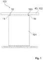
- Fig. 1 shows a sliding wall system 100 according to the invention, wherein a sliding wall element 101 of the sliding wall system 100 is shown.
- the sliding wall element 101 is at its upper end with a respective suspension element 14 of a carriage 10, in particular a carriage 10 according to the invention, and a drive carriage 103 connected.
- the carriage 10 and the drive carriage 103 are in turn arranged movable in a profile element 40 of a ceiling guide 102 of the sliding wall system 100.
- a movement in particular driven by a drive unit 20 (not shown) of the drive carriage 103, a movement of the sliding wall element 101 along the ceiling guide 102 can be performed.
- a variable pitch of a room in which such a sliding wall installation 100 is arranged can thereby be provided.
- the drive carriage 10 and the carriage 103 preferably not differ in size at least substantially.
- This can be provided in particular by the inventive design of a drive carriage 10, the drive unit 20 and the electric drive 21 in the interior of at least one of the wheels 11, 12 (each not shown) is arranged.
- Fig. 2 Two possible embodiments of a carriage 10 according to the invention are shown.
- the carriage 10 is also designed as a drive carriage 103.
- the two embodiments also differ in particular in an arrangement of the respective guide elements 32.
- the two embodiments are described together, wherein the specific differences will be discussed in each case.
- An inventive carriage 10 has a carriage housing 13, which accommodates at least an upper part of the carriage 10 in itself. From the upper surface of the carriage housing 13 protrude current collector 19, which provides a supply of electrical energy for electrical systems of the carriage 10 according to the invention, such as Sensor devices or for an electric drive 21 of a drive unit 20, for example, from a correspondingly in the ceiling guide 102 (not shown) installed busbar allow.
- a suspension element 14 is further arranged, which is provided for an arrangement of a sliding wall element 101 (not shown).
- the suspension element 14 in particular has a bearing element 16 which allows a rotation or a pivoting of the sliding wall element 101.
- the first impeller 11 and the second impeller 12 are further rotatably arranged.
- the running surfaces 17 of the wheels 11, 12 are formed offset.
- the running surfaces 17 of the wheels 11, 12 axially, ie along an impeller axis 60, formed shortened and have a comparison with the rest of the wheel 11, 12 by an impeller 18 enlarged radius.
- the carriage 10 according to the invention shown on the right is embodied as a drive carriage 103 and has an electric drive 21 of a drive unit 20, which is at least partially disposed in the interior of at least the first impeller 11, preferably also in the interior of the second impeller 12. Furthermore, it can be clearly seen that a drive axle 61 of the electric drive 21, which is particularly preferably at least substantially cylindrical, is arranged coaxially with an impeller axis 60, wherein as shown preferably the first impeller 11 and the second impeller 12 have a common impeller axis 60. Furthermore, the electric drive 21 is coupled to the first impeller 11 via a first coupling element 22, which is designed here as a planetary gear 24. A bearing of the wheels 11, 12 is provided by a bearing device 15.
- Both illustrated embodiments of a carriage 10 according to the invention have at least one arrangement element 30, on which guide elements 32 are arranged in different receiving positions 31.
- all shooting positions 31 are occupied by guide elements 32, but alternatively shooting positions 31 may remain free (not shown).
- at least one of the receiving positions 31 is always covered with a guide element 32 in a carriage 10 according to the invention.
- the embodiment shown on the left of a carriage 10 has two arrangement elements 30, one of which is arranged on the housing element and the other on the suspension element 14.
- a total of eight guide elements 32, which are formed as guide rollers can be arranged as shown in eight receiving positions 31.
- this arrangement element 30 has a plurality of receiving positions 31, in which, as shown, guide elements 32, in particular guide rollers, can be arranged.
- guide elements 32 in particular guide rollers
- two of the guide elements 32 are arranged in a receiving position 31 close to the arrangement element 30, the other two guide element 32 in a receiving position 31 further away from the arrangement element 30.
- such guide elements 32 can on the one hand ensure central positioning of the carriage 10 in a profile element 40 of a ceiling guide 102 (not shown in each case).
- a running direction of the carriage 10 according to the invention and thus the entire sliding wall element 101 are particularly simple.
- counter-guide elements 51 which are designed to contact the corresponding guide element 32 can be provided in the points sections.
- FIG. 3 and 4 This is in the Fig. 3 and 4 shown in which an inventive carriage 10 is shown in a switch section 45 of a profile element 40 according to the invention.
- the Fig. 3 and 4 will be described together below.
- a switch section 45 of a profile element 40 is shown, which can be used in a ceiling guide 102 of a sliding wall installation 100 according to the invention (each not shown), in FIG Fig. 4 in particular in a sectional view. It is clearly visible that a track 44, along which a carriage 10 can move in the ceiling guide 102, bifurcates in this switch section 45 into a first path section 46 and a second path section 47.
- a path 44 is composed in this preferred embodiment, at least from a first run profile 41, a second run profile 42 and a profile gap 43 arranged between the running profiles 41, 42 together.
- the wheels 11, 12 of the carriage 10 are each movable on one of the running profiles 41, 42 arranged and the suspension member 14, on which a sliding wall element 101 (not shown) can be arranged, extends through the profile gap 43.
- the points section 45 has a positioning element 50 on which, particularly preferably selectively and / or reversibly, counter-guide elements 51st can be arranged.
- Such symbolsleitelement 51, the corresponding guide element 32 both as Leitsteg 52 from the inside or as a guide curve 53 from outside contacting lead.
- Fig. 5 shows a first example of a determination of a travel path 44 of a carriage 10, as it can be provided in a sliding wall system 100 according to the invention by a carriage 10 according to the invention and a profile element 40 according to the invention.
- the example relates in particular to a start-up of two different parking spaces, in which two sliding wall elements 101 are already located in the figure, in FIG Fig. 5 denoted by X and Y.
- Each of the sliding wall elements 101 is suspended via a carriage 10 and a drive carriage 103 in the profile element 40 of the ceiling guide 102 of the sliding wall system 100 according to the invention.
- the two parking spaces are accessible through two switch sections 45, in Fig. 5 with A, B for the first parking space and C, D for the second parking space.
- Fig. 5 Left top in Fig. 5 is schematically shown an inventive profile element 40 with Gegenleitmaschinen 51 in six possible positions. All counter-guide elements 51 are formed as guide webs 52 and thus contact a corresponding guide element 32 from the inside. At the same time contactable by the Gegenleitmaschine 51 guide elements 32 are also shown.
- the carriage 10 of the sliding wall element 101 Y called, by a corresponding arrangement of its guide elements 32 in the points sections 45 A and B, the straight path section turns and turns in the switch section 45 C, however, in the corresponding parking position.
- the illustrated exemplary distribution of sliding wall elements 101 to different parking spaces in a sliding wall system 100 according to the invention only with passive elements, in particular the guide elements 32 of Rollers 10 according to the invention or the counter-guiding elements 51 of the profile elements 40 according to the invention are provided.
- a second example of a determination of a travel path 44 of a carriage 10 is shown in a sliding wall system 100 according to the invention, as it can be provided by a carriage 10 according to the invention and a profile element 40 according to the invention.
- This example relates in particular to a release wing of the sliding wall installation 100, in this case the sliding wall element 101 Y. The final position of the release wing is accessible via a switch section 45 A.
- Another illustrated sliding wall element 101 is shown in FIG Fig. 6 denoted by X.
- Each of the sliding wall elements 101 is in turn hung on a carriage 10 and a drive carriage 103 in the profile element 40 of the ceiling guide 102 of the sliding wall system 100 according to the invention.
- the two sliding wall elements 101 X and Y come from a parking space, which is accessible via two points sections 45, in Fig. 6 denoted by B and C.
- Fig. 6 Left top in Fig. 6 is schematically shown an inventive profile element 40 with counter-guide elements 51 in eight possible positions.
- the counterguide elements 51 are partially designed as guide webs 52 and partially as guide curves 53 and thus contact a guide element 32 correspondingly from the inside or from the outside. At the same time contactable by the Gegenleitmaschine 51 guide elements 32 are also shown.
- the guide element 32 is guided in the soft section 45 A by a trained as a guide web 52 Gegenleitelement 51 inside, and in the turnout section 45 B is guided outwardly contacted by trained as a guide cam 53 Sigmaleitelement 51.
- both a curved path with right curvature and a curved path with left curvature can be defined as the path 44.
- the determination of the paths 44 of the individual carriages 10 or drive carriages 103 can be provided only with passive elements, in particular the guide elements 32 of the carriages 10 according to the invention or the counter-guide elements 51 of the profile elements 40 according to the invention.
Landscapes
- Engineering & Computer Science (AREA)
- Mechanical Engineering (AREA)
- Power-Operated Mechanisms For Wings (AREA)
- Support Devices For Sliding Doors (AREA)
Priority Applications (1)
| Application Number | Priority Date | Filing Date | Title |
|---|---|---|---|
| EP16201283.5A EP3327232B1 (fr) | 2016-11-29 | 2016-11-29 | Chariot pour élément de cloison coulissante d'une installation de paroi coulissante, élément profilé pour le guidage au plafond d'une paroi coulissante et paroi coulissante |
Applications Claiming Priority (1)
| Application Number | Priority Date | Filing Date | Title |
|---|---|---|---|
| EP16201283.5A EP3327232B1 (fr) | 2016-11-29 | 2016-11-29 | Chariot pour élément de cloison coulissante d'une installation de paroi coulissante, élément profilé pour le guidage au plafond d'une paroi coulissante et paroi coulissante |
Publications (2)
| Publication Number | Publication Date |
|---|---|
| EP3327232A1 true EP3327232A1 (fr) | 2018-05-30 |
| EP3327232B1 EP3327232B1 (fr) | 2021-09-15 |
Family
ID=57471665
Family Applications (1)
| Application Number | Title | Priority Date | Filing Date |
|---|---|---|---|
| EP16201283.5A Active EP3327232B1 (fr) | 2016-11-29 | 2016-11-29 | Chariot pour élément de cloison coulissante d'une installation de paroi coulissante, élément profilé pour le guidage au plafond d'une paroi coulissante et paroi coulissante |
Country Status (1)
| Country | Link |
|---|---|
| EP (1) | EP3327232B1 (fr) |
Citations (3)
| Publication number | Priority date | Publication date | Assignee | Title |
|---|---|---|---|---|
| EP0719902A1 (fr) * | 1994-12-23 | 1996-07-03 | Hüppe Form Sonnenschutz- und Raumtrennsysteme GmbH | Elément de cloison mobile |
| DE202008011015U1 (de) * | 2008-08-18 | 2008-12-24 | Liao, Shou-Hsing | Aufhängungs- Rollen- Anordnung für bewegliche Trennelemente |
| WO2010108585A1 (fr) * | 2009-03-24 | 2010-09-30 | Dorma Gmbh + Co. Kg | Système de commande pour une installation de cloison séparative |
Family Cites Families (5)
| Publication number | Priority date | Publication date | Assignee | Title |
|---|---|---|---|---|
| CH585841A5 (fr) | 1975-04-11 | 1977-03-15 | Hawa Ag | |
| DE9211932U1 (de) | 1992-09-04 | 1993-01-14 | Haab, Karl, Rotkreuz | Schienensystem für Schiebetüren sowie Schiebetürsystem |
| JP2006506560A (ja) | 2002-07-05 | 2006-02-23 | ハバ アクチェンゲゼルシャフト | 移動可能な分離要素用の装置、駆動組立体及び分離要素 |
| EP1640543B1 (fr) | 2004-09-23 | 2016-06-01 | Hawa Ag | Dispositif de propulsion pour un élément de séparation coulissant |
| DE102013020650B3 (de) | 2013-12-16 | 2015-05-28 | Geze Gmbh | Schiebewand- oder Schiebetürsystem |
-
2016
- 2016-11-29 EP EP16201283.5A patent/EP3327232B1/fr active Active
Patent Citations (3)
| Publication number | Priority date | Publication date | Assignee | Title |
|---|---|---|---|---|
| EP0719902A1 (fr) * | 1994-12-23 | 1996-07-03 | Hüppe Form Sonnenschutz- und Raumtrennsysteme GmbH | Elément de cloison mobile |
| DE202008011015U1 (de) * | 2008-08-18 | 2008-12-24 | Liao, Shou-Hsing | Aufhängungs- Rollen- Anordnung für bewegliche Trennelemente |
| WO2010108585A1 (fr) * | 2009-03-24 | 2010-09-30 | Dorma Gmbh + Co. Kg | Système de commande pour une installation de cloison séparative |
Also Published As
| Publication number | Publication date |
|---|---|
| EP3327232B1 (fr) | 2021-09-15 |
Similar Documents
| Publication | Publication Date | Title |
|---|---|---|
| EP2291573B1 (fr) | Système d 'entraînement pour entraîner et pour guider un élément de cloison pour un système de cloison de séparation d' espace | |
| EP2732519B1 (fr) | Système de guidage de câbles | |
| WO1999057457A1 (fr) | Chaine de guidage d'elements de transport d'energie | |
| EP3464010B1 (fr) | Système de transport à rails et véhicule ferroviaire pour un système de transport à rails | |
| EP0597208B1 (fr) | Cloison amovible à plusieurs panneaux de murs | |
| DE102010021594B4 (de) | Schienensystem, insbesondere für eine Elektro-Palettenbahn | |
| EP1299276B1 (fr) | Systeme de transport | |
| EP2406450B1 (fr) | Système d'entraînement pour l'entraînement et le guidage d'un élément de cloison pour un système de cloison de séparation d'espace | |
| DE2659010C3 (de) | Weiche für ein Zweischienengleis für Magnetschwebefahrzeuge | |
| EP3327232A1 (fr) | Chariot pour élément de cloison coulissante d'une installation de paroi coulissante, élément profilé pour le guidage au plafond d'une paroi coulissante et paroi coulissante | |
| EP1249406A1 (fr) | Dispositif de renvoi pour convoyeur | |
| DE2919876C2 (fr) | ||
| DE69507133T2 (de) | Vorrichtung bei hängeförderern | |
| EP3327231B1 (fr) | Chariot pour élément de paroi coulissante d'une installation de paroi coulissante et installation de paroi coulissante | |
| EP2014854B1 (fr) | Actionnement de porte pour au moins un vantail de porte dans un véhicule | |
| EP3327230B1 (fr) | Chariot d'entraînement pour élément de paroi coulissante d'une installation de paroi coulissante ainsi que paroi coulissante | |
| EP3002079B1 (fr) | Systeme de glissiere | |
| EP3347299B1 (fr) | Rail de guidage pour un système d'ascenseur | |
| EP2679740A1 (fr) | Paroi de séparation mobile | |
| DE102011077917A1 (de) | Vorrichtung zur Nutzung von Strömungsenergie | |
| EP2884032B1 (fr) | Système de porte coulissante ou de paroi coulissante | |
| EP0881343A1 (fr) | Appareil de parcage pour automobiles avec au moins deux places de parking superposées | |
| DE29609982U1 (de) | Antriebssystem für eine Bogenschiebetür | |
| DE202014002511U1 (de) | Anordnung von Energieführungsketten und Führungsrinnen zum Führen von flexiblen Leitungen | |
| EP1197423B1 (fr) | Dispositif de levage |
Legal Events
| Date | Code | Title | Description |
|---|---|---|---|
| PUAI | Public reference made under article 153(3) epc to a published international application that has entered the european phase |
Free format text: ORIGINAL CODE: 0009012 |
|
| STAA | Information on the status of an ep patent application or granted ep patent |
Free format text: STATUS: THE APPLICATION HAS BEEN PUBLISHED |
|
| AK | Designated contracting states |
Kind code of ref document: A1 Designated state(s): AL AT BE BG CH CY CZ DE DK EE ES FI FR GB GR HR HU IE IS IT LI LT LU LV MC MK MT NL NO PL PT RO RS SE SI SK SM TR |
|
| AX | Request for extension of the european patent |
Extension state: BA ME |
|
| STAA | Information on the status of an ep patent application or granted ep patent |
Free format text: STATUS: REQUEST FOR EXAMINATION WAS MADE |
|
| 17P | Request for examination filed |
Effective date: 20181128 |
|
| RBV | Designated contracting states (corrected) |
Designated state(s): AL AT BE BG CH CY CZ DE DK EE ES FI FR GB GR HR HU IE IS IT LI LT LU LV MC MK MT NL NO PL PT RO RS SE SI SK SM TR |
|
| STAA | Information on the status of an ep patent application or granted ep patent |
Free format text: STATUS: EXAMINATION IS IN PROGRESS |
|
| 17Q | First examination report despatched |
Effective date: 20191024 |
|
| GRAP | Despatch of communication of intention to grant a patent |
Free format text: ORIGINAL CODE: EPIDOSNIGR1 |
|
| STAA | Information on the status of an ep patent application or granted ep patent |
Free format text: STATUS: GRANT OF PATENT IS INTENDED |
|
| INTG | Intention to grant announced |
Effective date: 20210408 |
|
| RIN1 | Information on inventor provided before grant (corrected) |
Inventor name: DUENNINGHAUS, TORSTEN |
|
| GRAS | Grant fee paid |
Free format text: ORIGINAL CODE: EPIDOSNIGR3 |
|
| GRAA | (expected) grant |
Free format text: ORIGINAL CODE: 0009210 |
|
| STAA | Information on the status of an ep patent application or granted ep patent |
Free format text: STATUS: THE PATENT HAS BEEN GRANTED |
|
| AK | Designated contracting states |
Kind code of ref document: B1 Designated state(s): AL AT BE BG CH CY CZ DE DK EE ES FI FR GB GR HR HU IE IS IT LI LT LU LV MC MK MT NL NO PL PT RO RS SE SI SK SM TR |
|
| REG | Reference to a national code |
Ref country code: CH Ref legal event code: EP Ref country code: GB Ref legal event code: FG4D Free format text: NOT ENGLISH |
|
| REG | Reference to a national code |
Ref country code: DE Ref legal event code: R096 Ref document number: 502016013827 Country of ref document: DE |
|
| REG | Reference to a national code |
Ref country code: IE Ref legal event code: FG4D Free format text: LANGUAGE OF EP DOCUMENT: GERMAN |
|
| REG | Reference to a national code |
Ref country code: AT Ref legal event code: REF Ref document number: 1430650 Country of ref document: AT Kind code of ref document: T Effective date: 20211015 |
|
| REG | Reference to a national code |
Ref country code: LT Ref legal event code: MG9D |
|
| REG | Reference to a national code |
Ref country code: NL Ref legal event code: MP Effective date: 20210915 |
|
| PG25 | Lapsed in a contracting state [announced via postgrant information from national office to epo] |
Ref country code: LT Free format text: LAPSE BECAUSE OF FAILURE TO SUBMIT A TRANSLATION OF THE DESCRIPTION OR TO PAY THE FEE WITHIN THE PRESCRIBED TIME-LIMIT Effective date: 20210915 Ref country code: BG Free format text: LAPSE BECAUSE OF FAILURE TO SUBMIT A TRANSLATION OF THE DESCRIPTION OR TO PAY THE FEE WITHIN THE PRESCRIBED TIME-LIMIT Effective date: 20211215 Ref country code: NO Free format text: LAPSE BECAUSE OF FAILURE TO SUBMIT A TRANSLATION OF THE DESCRIPTION OR TO PAY THE FEE WITHIN THE PRESCRIBED TIME-LIMIT Effective date: 20211215 Ref country code: FI Free format text: LAPSE BECAUSE OF FAILURE TO SUBMIT A TRANSLATION OF THE DESCRIPTION OR TO PAY THE FEE WITHIN THE PRESCRIBED TIME-LIMIT Effective date: 20210915 Ref country code: SE Free format text: LAPSE BECAUSE OF FAILURE TO SUBMIT A TRANSLATION OF THE DESCRIPTION OR TO PAY THE FEE WITHIN THE PRESCRIBED TIME-LIMIT Effective date: 20210915 Ref country code: RS Free format text: LAPSE BECAUSE OF FAILURE TO SUBMIT A TRANSLATION OF THE DESCRIPTION OR TO PAY THE FEE WITHIN THE PRESCRIBED TIME-LIMIT Effective date: 20210915 Ref country code: HR Free format text: LAPSE BECAUSE OF FAILURE TO SUBMIT A TRANSLATION OF THE DESCRIPTION OR TO PAY THE FEE WITHIN THE PRESCRIBED TIME-LIMIT Effective date: 20210915 |
|
| PG25 | Lapsed in a contracting state [announced via postgrant information from national office to epo] |
Ref country code: LV Free format text: LAPSE BECAUSE OF FAILURE TO SUBMIT A TRANSLATION OF THE DESCRIPTION OR TO PAY THE FEE WITHIN THE PRESCRIBED TIME-LIMIT Effective date: 20210915 Ref country code: GR Free format text: LAPSE BECAUSE OF FAILURE TO SUBMIT A TRANSLATION OF THE DESCRIPTION OR TO PAY THE FEE WITHIN THE PRESCRIBED TIME-LIMIT Effective date: 20211216 |
|
| PG25 | Lapsed in a contracting state [announced via postgrant information from national office to epo] |
Ref country code: IS Free format text: LAPSE BECAUSE OF FAILURE TO SUBMIT A TRANSLATION OF THE DESCRIPTION OR TO PAY THE FEE WITHIN THE PRESCRIBED TIME-LIMIT Effective date: 20220115 Ref country code: SM Free format text: LAPSE BECAUSE OF FAILURE TO SUBMIT A TRANSLATION OF THE DESCRIPTION OR TO PAY THE FEE WITHIN THE PRESCRIBED TIME-LIMIT Effective date: 20210915 Ref country code: SK Free format text: LAPSE BECAUSE OF FAILURE TO SUBMIT A TRANSLATION OF THE DESCRIPTION OR TO PAY THE FEE WITHIN THE PRESCRIBED TIME-LIMIT Effective date: 20210915 Ref country code: RO Free format text: LAPSE BECAUSE OF FAILURE TO SUBMIT A TRANSLATION OF THE DESCRIPTION OR TO PAY THE FEE WITHIN THE PRESCRIBED TIME-LIMIT Effective date: 20210915 Ref country code: PT Free format text: LAPSE BECAUSE OF FAILURE TO SUBMIT A TRANSLATION OF THE DESCRIPTION OR TO PAY THE FEE WITHIN THE PRESCRIBED TIME-LIMIT Effective date: 20220117 Ref country code: PL Free format text: LAPSE BECAUSE OF FAILURE TO SUBMIT A TRANSLATION OF THE DESCRIPTION OR TO PAY THE FEE WITHIN THE PRESCRIBED TIME-LIMIT Effective date: 20210915 Ref country code: NL Free format text: LAPSE BECAUSE OF FAILURE TO SUBMIT A TRANSLATION OF THE DESCRIPTION OR TO PAY THE FEE WITHIN THE PRESCRIBED TIME-LIMIT Effective date: 20210915 Ref country code: ES Free format text: LAPSE BECAUSE OF FAILURE TO SUBMIT A TRANSLATION OF THE DESCRIPTION OR TO PAY THE FEE WITHIN THE PRESCRIBED TIME-LIMIT Effective date: 20210915 Ref country code: EE Free format text: LAPSE BECAUSE OF FAILURE TO SUBMIT A TRANSLATION OF THE DESCRIPTION OR TO PAY THE FEE WITHIN THE PRESCRIBED TIME-LIMIT Effective date: 20210915 Ref country code: CZ Free format text: LAPSE BECAUSE OF FAILURE TO SUBMIT A TRANSLATION OF THE DESCRIPTION OR TO PAY THE FEE WITHIN THE PRESCRIBED TIME-LIMIT Effective date: 20210915 Ref country code: AL Free format text: LAPSE BECAUSE OF FAILURE TO SUBMIT A TRANSLATION OF THE DESCRIPTION OR TO PAY THE FEE WITHIN THE PRESCRIBED TIME-LIMIT Effective date: 20210915 |
|
| REG | Reference to a national code |
Ref country code: DE Ref legal event code: R026 Ref document number: 502016013827 Country of ref document: DE |
|
| PLBI | Opposition filed |
Free format text: ORIGINAL CODE: 0009260 |
|
| PLAB | Opposition data, opponent's data or that of the opponent's representative modified |
Free format text: ORIGINAL CODE: 0009299OPPO |
|
| PLAX | Notice of opposition and request to file observation + time limit sent |
Free format text: ORIGINAL CODE: EPIDOSNOBS2 |
|
| PG25 | Lapsed in a contracting state [announced via postgrant information from national office to epo] |
Ref country code: MC Free format text: LAPSE BECAUSE OF FAILURE TO SUBMIT A TRANSLATION OF THE DESCRIPTION OR TO PAY THE FEE WITHIN THE PRESCRIBED TIME-LIMIT Effective date: 20210915 |
|
| REG | Reference to a national code |
Ref country code: CH Ref legal event code: PL |
|
| 26 | Opposition filed |
Opponent name: GEZE GMBH Effective date: 20220615 |
|
| R26 | Opposition filed (corrected) |
Opponent name: GEZE GMBH Effective date: 20220615 |
|
| PG25 | Lapsed in a contracting state [announced via postgrant information from national office to epo] |
Ref country code: LU Free format text: LAPSE BECAUSE OF NON-PAYMENT OF DUE FEES Effective date: 20211129 Ref country code: DK Free format text: LAPSE BECAUSE OF FAILURE TO SUBMIT A TRANSLATION OF THE DESCRIPTION OR TO PAY THE FEE WITHIN THE PRESCRIBED TIME-LIMIT Effective date: 20210915 Ref country code: BE Free format text: LAPSE BECAUSE OF NON-PAYMENT OF DUE FEES Effective date: 20211130 |
|
| REG | Reference to a national code |
Ref country code: BE Ref legal event code: MM Effective date: 20211130 |
|
| GBPC | Gb: european patent ceased through non-payment of renewal fee |
Effective date: 20211215 |
|
| PG25 | Lapsed in a contracting state [announced via postgrant information from national office to epo] |
Ref country code: SI Free format text: LAPSE BECAUSE OF FAILURE TO SUBMIT A TRANSLATION OF THE DESCRIPTION OR TO PAY THE FEE WITHIN THE PRESCRIBED TIME-LIMIT Effective date: 20210915 Ref country code: LI Free format text: LAPSE BECAUSE OF NON-PAYMENT OF DUE FEES Effective date: 20211130 Ref country code: CH Free format text: LAPSE BECAUSE OF NON-PAYMENT OF DUE FEES Effective date: 20211130 |
|
| PG25 | Lapsed in a contracting state [announced via postgrant information from national office to epo] |
Ref country code: IE Free format text: LAPSE BECAUSE OF NON-PAYMENT OF DUE FEES Effective date: 20211129 Ref country code: GB Free format text: LAPSE BECAUSE OF NON-PAYMENT OF DUE FEES Effective date: 20211215 |
|
| PLBB | Reply of patent proprietor to notice(s) of opposition received |
Free format text: ORIGINAL CODE: EPIDOSNOBS3 |
|
| PG25 | Lapsed in a contracting state [announced via postgrant information from national office to epo] |
Ref country code: FR Free format text: LAPSE BECAUSE OF NON-PAYMENT OF DUE FEES Effective date: 20211130 |
|
| REG | Reference to a national code |
Ref country code: AT Ref legal event code: MM01 Ref document number: 1430650 Country of ref document: AT Kind code of ref document: T Effective date: 20211129 |
|
| PG25 | Lapsed in a contracting state [announced via postgrant information from national office to epo] |
Ref country code: IT Free format text: LAPSE BECAUSE OF FAILURE TO SUBMIT A TRANSLATION OF THE DESCRIPTION OR TO PAY THE FEE WITHIN THE PRESCRIBED TIME-LIMIT Effective date: 20210915 Ref country code: AT Free format text: LAPSE BECAUSE OF NON-PAYMENT OF DUE FEES Effective date: 20211129 |
|
| PG25 | Lapsed in a contracting state [announced via postgrant information from national office to epo] |
Ref country code: HU Free format text: LAPSE BECAUSE OF FAILURE TO SUBMIT A TRANSLATION OF THE DESCRIPTION OR TO PAY THE FEE WITHIN THE PRESCRIBED TIME-LIMIT; INVALID AB INITIO Effective date: 20161129 |
|
| PG25 | Lapsed in a contracting state [announced via postgrant information from national office to epo] |
Ref country code: CY Free format text: LAPSE BECAUSE OF FAILURE TO SUBMIT A TRANSLATION OF THE DESCRIPTION OR TO PAY THE FEE WITHIN THE PRESCRIBED TIME-LIMIT Effective date: 20210915 |
|
| REG | Reference to a national code |
Ref country code: DE Ref legal event code: R100 Ref document number: 502016013827 Country of ref document: DE |
|
| PLCK | Communication despatched that opposition was rejected |
Free format text: ORIGINAL CODE: EPIDOSNREJ1 |
|
| PLBN | Opposition rejected |
Free format text: ORIGINAL CODE: 0009273 |
|
| STAA | Information on the status of an ep patent application or granted ep patent |
Free format text: STATUS: OPPOSITION REJECTED |
|
| 27O | Opposition rejected |
Effective date: 20230919 |
|
| PG25 | Lapsed in a contracting state [announced via postgrant information from national office to epo] |
Ref country code: MK Free format text: LAPSE BECAUSE OF FAILURE TO SUBMIT A TRANSLATION OF THE DESCRIPTION OR TO PAY THE FEE WITHIN THE PRESCRIBED TIME-LIMIT Effective date: 20210915 |
|
| PG25 | Lapsed in a contracting state [announced via postgrant information from national office to epo] |
Ref country code: MT Free format text: LAPSE BECAUSE OF FAILURE TO SUBMIT A TRANSLATION OF THE DESCRIPTION OR TO PAY THE FEE WITHIN THE PRESCRIBED TIME-LIMIT Effective date: 20210915 |
|
| PG25 | Lapsed in a contracting state [announced via postgrant information from national office to epo] |
Ref country code: TR Free format text: LAPSE BECAUSE OF FAILURE TO SUBMIT A TRANSLATION OF THE DESCRIPTION OR TO PAY THE FEE WITHIN THE PRESCRIBED TIME-LIMIT Effective date: 20210915 |
|
| PGFP | Annual fee paid to national office [announced via postgrant information from national office to epo] |
Ref country code: DE Payment date: 20251119 Year of fee payment: 10 |