EP0719939B1 - Moteur piézoélectrique à ondes progressives pour pompe à tube d'entrefer - Google Patents
Moteur piézoélectrique à ondes progressives pour pompe à tube d'entrefer Download PDFInfo
- Publication number
- EP0719939B1 EP0719939B1 EP95120172A EP95120172A EP0719939B1 EP 0719939 B1 EP0719939 B1 EP 0719939B1 EP 95120172 A EP95120172 A EP 95120172A EP 95120172 A EP95120172 A EP 95120172A EP 0719939 B1 EP0719939 B1 EP 0719939B1
- Authority
- EP
- European Patent Office
- Prior art keywords
- separating element
- pump
- rotor
- rotary wheel
- piezo elements
- Prior art date
- Legal status (The legal status is an assumption and is not a legal conclusion. Google has not performed a legal analysis and makes no representation as to the accuracy of the status listed.)
- Expired - Lifetime
Links
- 230000000750 progressive effect Effects 0.000 title claims 7
- 239000012790 adhesive layer Substances 0.000 claims description 17
- 238000007789 sealing Methods 0.000 claims description 4
- 230000002093 peripheral effect Effects 0.000 claims 1
- 238000005520 cutting process Methods 0.000 description 5
- 239000011324 bead Substances 0.000 description 3
- 238000006073 displacement reaction Methods 0.000 description 2
- 239000002245 particle Substances 0.000 description 2
- 238000011109 contamination Methods 0.000 description 1
- 238000001816 cooling Methods 0.000 description 1
- 239000013078 crystal Substances 0.000 description 1
- 210000003746 feather Anatomy 0.000 description 1
- 239000012530 fluid Substances 0.000 description 1
- 238000004519 manufacturing process Methods 0.000 description 1
- 230000005012 migration Effects 0.000 description 1
- 238000013508 migration Methods 0.000 description 1
- 230000000737 periodic effect Effects 0.000 description 1
- 238000003825 pressing Methods 0.000 description 1
- 238000005086 pumping Methods 0.000 description 1
- 238000000926 separation method Methods 0.000 description 1
- 238000003860 storage Methods 0.000 description 1
- 238000004804 winding Methods 0.000 description 1
Images



Classifications
-
- H—ELECTRICITY
- H02—GENERATION; CONVERSION OR DISTRIBUTION OF ELECTRIC POWER
- H02N—ELECTRIC MACHINES NOT OTHERWISE PROVIDED FOR
- H02N2/00—Electric machines in general using piezoelectric effect, electrostriction or magnetostriction
- H02N2/10—Electric machines in general using piezoelectric effect, electrostriction or magnetostriction producing rotary motion, e.g. rotary motors
- H02N2/16—Electric machines in general using piezoelectric effect, electrostriction or magnetostriction producing rotary motion, e.g. rotary motors using travelling waves, i.e. Rayleigh surface waves
- H02N2/163—Motors with ring stator
-
- F—MECHANICAL ENGINEERING; LIGHTING; HEATING; WEAPONS; BLASTING
- F04—POSITIVE - DISPLACEMENT MACHINES FOR LIQUIDS; PUMPS FOR LIQUIDS OR ELASTIC FLUIDS
- F04D—NON-POSITIVE-DISPLACEMENT PUMPS
- F04D13/00—Pumping installations or systems
- F04D13/02—Units comprising pumps and their driving means
- F04D13/06—Units comprising pumps and their driving means the pump being electrically driven
- F04D13/0606—Canned motor pumps
- F04D13/0626—Details of the can
-
- F—MECHANICAL ENGINEERING; LIGHTING; HEATING; WEAPONS; BLASTING
- F04—POSITIVE - DISPLACEMENT MACHINES FOR LIQUIDS; PUMPS FOR LIQUIDS OR ELASTIC FLUIDS
- F04D—NON-POSITIVE-DISPLACEMENT PUMPS
- F04D13/00—Pumping installations or systems
- F04D13/02—Units comprising pumps and their driving means
- F04D13/06—Units comprising pumps and their driving means the pump being electrically driven
- F04D13/0606—Canned motor pumps
- F04D13/0633—Details of the bearings
-
- F—MECHANICAL ENGINEERING; LIGHTING; HEATING; WEAPONS; BLASTING
- F04—POSITIVE - DISPLACEMENT MACHINES FOR LIQUIDS; PUMPS FOR LIQUIDS OR ELASTIC FLUIDS
- F04D—NON-POSITIVE-DISPLACEMENT PUMPS
- F04D13/00—Pumping installations or systems
- F04D13/02—Units comprising pumps and their driving means
- F04D13/06—Units comprising pumps and their driving means the pump being electrically driven
- F04D13/0606—Canned motor pumps
- F04D13/064—Details of the magnetic circuit
-
- F—MECHANICAL ENGINEERING; LIGHTING; HEATING; WEAPONS; BLASTING
- F04—POSITIVE - DISPLACEMENT MACHINES FOR LIQUIDS; PUMPS FOR LIQUIDS OR ELASTIC FLUIDS
- F04D—NON-POSITIVE-DISPLACEMENT PUMPS
- F04D13/00—Pumping installations or systems
- F04D13/02—Units comprising pumps and their driving means
- F04D13/06—Units comprising pumps and their driving means the pump being electrically driven
- F04D13/0666—Units comprising pumps and their driving means the pump being electrically driven the motor being of the plane gap type
Definitions
- the invention relates to a pump with a in a housing arranged impeller and a separator that the medium leading side from the electrical drive side separates, the separating element in particular a can, Can or a split washer
- the object of the invention is therefore the impeller Canned tube pump using a piezo traveling wave motor described above drive.
- the Impeller is driven by a piezo traveling wave motor, wherein the piezo traveling wave motor has piezo elements that one Set the vibration stator in vibration and the separating element Is a vibration stator.
- the separating element takes on two functions. That's how it separates Separating element on the one hand, the medium carrying the side of the electric drive side and is also the oscillating stator of the Piezo-traveling wave motor. This is where the drive comes from Can pump with few parts and is therefore extremely compact and therefore inexpensive and easy to manufacture.
- the impeller or a rotor carrying the impeller lies here advantageously on the separating element and is by means of a Surface of the separating element revolving traveling wave in Rotation can be set.
- the impeller or the rotor at least partially with its Shell surface on the cylindrical inside of the separating element on or with its end facing away from the pump inlet side on the separating element.
- the piezo elements of the piezo traveling wave motor are on the the impeller or the rotor facing away from the separating element on.
- piezo elements in or on Separating element are arranged and in the circumferential direction of the Impeller when applying electrical voltages to generate the Traveling wave on the separating element in particular by its length an AC voltage is changeable.
- the piezo elements is e.g. B. known from DE 3927040.
- the advantage of this arrangement of the piezo elements is that in the stator of the piezo traveling wave motor different vibration modes stimulated and influencing dynamic properties such as Rotation speed or torque can be used.
- the impeller or the rotor is a has special contact surface on the separating element in the area of adjacent piezo elements, being on the contact surface is an adhesive layer in which at least the wave crests of the the traveling wave generated on the surface of the separating element intervention.
- the impeller or the rotor sealingly rests on the separating element, causing the medium to be pumped due to the additional sealing not in the area of Bearing of the impeller or the rotor can reach.
- the Adhesive layer advantageously takes over the sealing.
- this has Separating element on its side facing the impeller Collar, wherein the separating element with the collar sealing on Housing rests and hereby the mounting opening for the Pump impeller closes.
- the contact surface can also be straight, the Rotor or the impeller in an annular groove in the Separating element is inserted. Also the rotor or the impeller have a cylindrical groove in the one on the separating element molded cylindrical projection.
- the piezo element control Electronics is in direct contact with the separating element. This allows the heat generated by the electronics directly via the separating element be derived to the medium.
- the piezo elements For easy assembly of the piezo elements, they can be attached to the Arranged or fixed inner surface of a cylindrical sleeve his. For assembly only the pre-assembled sleeve with the Piezo elements are arranged accordingly on the separating element.
- this is Separating element non-positively and / or positively by means of a Housing cover held in position on the housing.
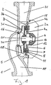
- FIG. 1 shows a pump 1 in its housing 2, an impeller 3 is rotatably arranged.
- the impeller 3 is on a shaft 20 attached, the roller bearing 14 on the separator 4th (Containment shell) is stored.
- the impeller 3 is axial Direction on the impeller inlet side 3c by means of a Plain bearing 16 mounted, the plain bearing in addition has a seal that the pump suction 10 from the Pump outlet side 21 separates.
- the impeller 3 is by means of Plain bearing 16 with its located on the end face 3b Adhesive layer 11 against the collar 4b of the containment shell or
- the piezo elements 8 By means of the piezo elements 8, the on the side of the collar 4b facing away from the pump impeller 3 of the separating element 4 will rest, at least in the area of Contact surface of the piezo elements 8, the collar 4 b in vibration added. To this end, the piezo elements 8 are attached to them applied voltages periodically their length in axial direction.
- the collar 4b of the can 4 takes over Function of the vibrating body or vibrating stator of the known Piezo-traveling wave motors.
- Adhesive layer 11 of the impeller 3 generates a surface wave, their maxima in the adhesive layer 11 of the impeller 3 intervene by the elliptical movement of the Surface particles of the vibrating stator surface 4a the impeller 3 in the opposite direction of the surface wave is taken away.
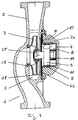
- FIG 2 also shows a centrifugal pump in which the Electronics 12 by means of a split disk 4 from the pumping medium-carrying side 5 of the pump 1 is separated.
- the Splitting disk 4 is in such a way by means of the piezo elements 8 in Vibration offset that on its surface 4a Traveling wave arises, the maxima in the adhesive layer 11 of the Engage impeller 3 and set it in rotation.
- the Impeller 3 is pressed against the by means of a pressure plate 15 Surface 4a of the cutting disc 4 pressed, causing a Non-positive connection between the adhesive layer 11 and the surface 4a arises.
- the pressure plate 15 is thereby via a spring 17th or a pressure screw 17 which is anchored in the shaft 20 is pressed.
- the shaft 20 is on the cutting disc 4th molded or attached accordingly.
- the impeller can be as in Figure 2 shown by means of a roller bearing 14 on the shaft 20 be stored. However, it is also any other type of Storage conceivable.
- the electronics 12 lie in the housing cover 2a and is connected to the piezo elements 8 by means of electrical Connection line in electrical contact.
- the housing cover 2a lies sealingly at 18 on the housing 2, whereby the Electronics 12 and the piezo elements 8 against contamination are protected.
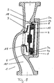
- FIG. 3 shows a further embodiment of a corresponding centrifugal pump 1, the impeller 3 between a plain bearing 16 and the cutting disc 4 rotatably.
- the cutting disc 4 is on its surface side 4a in the area the adjacent adhesive layer 11 of the impeller 3 to the outside (concave) curved.
- This curvature is ring-shaped, which means the adhesive layer 11 always covers the bead or on or encloses.
- the surface of the adhesive layer 11 or Impeller 3 is in accordance with the convex bead Surface 4a is convex, resulting in a convex Annular groove on the side of the cutting disc 4 facing the Impeller 3 results. Because of the ring-shaped bead that is Impeller 3 held in the radial direction, which means no further Bearing or shaft necessary to hold the impeller 3 is.
- FIG. 4 shows a further embodiment of the canned pump according to the invention, wherein the piezo elements rest against the cylindrical outer surface of the containment shell 4 and a traveling wave on the side facing away from the piezo elements 8 Create side 4a of the can 4.
- the piezo elements 8 facing away from the inside of the cylindrical wall of the The shell 9 of the can 4 rests with its outer surface, an adhesive layer 11 on the lateral surface of the rotor 9 is attached, in which the maxima on the inside of the cylindrical part of the can 4 generated Intervene surface wave.
- the rotor 9 is non-positively and / or positively on a shaft 20, which on an additional shaft bearing 14 on Canister base is stored. Such an additional warehouse however, is not mandatory.
- On the shaft 20 is the impeller 3 arranged. Through the surface wave of the Can 4, the rotor 9 is rotated and with it the shaft 20 and the impeller 3.
- Control electronics 12 arranged for the piezo elements 8.
- the Control electronics 12 advantageously lie on the containment can 4 on, which ensures good cooling by the can on the 4th fluid flowing past is guaranteed.
- Figures 5 to 7 show an enlarged section A of Centrifugal pump from Figure 4.
- guide of the rotor 9 is an additional Bearing of the shaft 20 or the impeller 3 is no longer necessary.
- the piezo elements 8 can, as in FIGS. 5 to 7 shown in a groove in the cylindrical inner surface 13a a mounting sleeve 13 lie, whereby they are opposite one axial displacement are secured.
- the piezo elements 8 are located on the side of the cylindrical side facing away from the rotor 9 Shell surface of the can 4.
- the cylindrical inner surface 4a of the cylindrical containment shell can move outwards (FIG. 6) or curved inwards (FIG. 7). It is also possible as shown in Figure 5 that the rotor 9 with its Adhesive layer 11 in a cylindrical groove 4c of the can 4 lies and thus against axial displacement is prevented from the containment shell 4.
- FIG. 8 shows a can pump 1 in which the impeller 3 additionally takes over the function of the rotor.
- Impeller 3 has an adhesive layer 11 on its outer surface 3a the inside of the facing away from the piezo elements 8 Can 4 rests. In this adhesive layer, not shown 11 grab the maxima of those generated on the surface 4a Traveling wave and drive the impeller 3.
- the piezo elements 8 lie between the cylindrical outer surface of the Containment shell 4 and the cylindrical inner surface of a Can 4 or a sleeve 13.
- the sleeve 13 can additionally carry the electronics 12.
- the housing cover 2a are electronics 12 and piezo elements 8 opposite Pollution protected.
- the housing cover 2a can additionally the function of pressing the can collar 4b against the Take over housing 2. This makes additional ones Fastening means, in particular screws for the containment shell 4 not necessary anymore.
Landscapes
- Engineering & Computer Science (AREA)
- Mechanical Engineering (AREA)
- General Engineering & Computer Science (AREA)
- Structures Of Non-Positive Displacement Pumps (AREA)
- General Electrical Machinery Utilizing Piezoelectricity, Electrostriction Or Magnetostriction (AREA)
Claims (14)
- Pompe (1) avec une roue mobile disposée dans un carter (2) et un élément séparateur (4) qui sépare le côté de guidage du liquide refoulé (5) d'avec le côté d'entraínement électrique (6), l'élément séparateur (4) étant en particulier une gaine à fente, une coupelle à fente ou un disque à fente et la roue mobile (3) étant entraínée au moyen d'un moteur piézoélectrique à ondes progressives (7),
caractérisée en ce que le moteur piézoélectrique à ondes progressives (7) a des éléments piézoélectriques qui mettent en oscillation un stator oscillant et l'élément séparateur (4) est le stator oscillant. - Pompe (1) selon la revendication 1,
caractérisée en ce que la roue mobile (3) ou un rotor (9) portant la roue mobile (3) est adjacent à l'élément séparateur (4) et peut être mis en rotation au moyen d'une onde progressive circulant sur la surface (4a) de l'élément séparateur (4). - Pompe (1) selon la revendication 2,
caractérisée en ce que la roue mobile (3) ou le rotor (9) est partiellement adjacent à la face intérieure (4a) cylindrique de l'élément séparateur (4) par sa surface périphérique (3a, 9a) ou à l'élément séparateur (4) par sa face frontale (3b, 9b) écartée du côté admission (10) de la pompe. - Pompe (1) selon la revendication 3,
caractérisée en ce que les éléments piézoélectriques (8) sont adjacents à la face de l'élément séparateur (4) écartée de la roue mobile (3) ou du rotor (9) et la longueur des éléments piézoélectriques (8) est modifiable en direction des normales de surface des surfaces d'appui (3a, 3b, 9a, 9b), au moyen de tensions électriques, pour engendrer l'onde progressive sur l'élément séparateur (4). - Pompe (1) selon la revendication 3,
caractérisée en ce que les éléments piézoélectriques (8) sont disposés dans ou sur l'élément séparateur (4) et leur longueur est modifiable en direction périphérique de la roue mobile (3) par application de tensions électriques pour engendrer l'onde progressive sur l'élément séparateur (4). - Pompe (1) selon l'une des revendications précédentes,
caractérisée en ce que la roue mobile (3) ou le rotor (9) a une surface d'appui (3a, 3b, 9a, 9b) qui est adjacente à l'élément séparateur (4) et sur la surface d'appui (3a, 3b, 9a, 9b) se trouve une couche adhésive (11) dans laquelle sont engagés au moins les crêtes de l'onde progressive engendrée sur la surface de l'élément séparateur (4). - Pompe (1) selon l'une des revendications précédentes,
caractérisée en ce que la roue mobile (3) ou le rotor (9) est adjacent à l'élément séparateur (4) de manière étanche. - Pompe (1) selon l'une des revendications précédentes,
caractérisée en ce que l'élément séparateur (4) a une collerette (4b) sur sa face tournée vers la roue mobile (3). - Pompe (1) selon la revendication 8,
caractérisée en ce que l'élément séparateur (4) est adjacent de manière étanche, par sa collerette (4b), au carter (2). - Pompe (1) selon l'une des revendications précédentes,
caractérisée en ce que la roue mobile (3) ou le rotor (9) est logé en direction axiale et/ou radiale au moyen de l'élément séparateur (4). - Pompe (1) selon l'une des revendications précédentes,
caractérisée en ce que la surface d'appui (3a, 3b, 9a, 9b) de la roue mobile (3) ou du rotor (9) est conformée au moins partiellement concave ou convexe et la surface (4a) de l'élément séparateur (4) est conformée dans la zone de la surface d'appui (3a, 3b, 9a, 9b) adjacente de la roue mobile (3) ou du rotor (9), convexe dans le cas d'une surface d'appui (3a, 3b, 9a, 9b) conformée concave et concave dans le cas d'une surface d'appui (3a, 3b, 9a, 9b) de la roue mobile (3) ou du rotor (9) conformée convexe. - Pompe (1) selon l'une des revendications précédentes,
caractérisée en ce que l'électronique (12) commandant les éléments piézoélectriques (8) est adjacente à l'élément séparateur (4). - Pompe (1) selon l'une des revendications précédentes,
caractérisée en ce que les éléments piézoélectriques (8) sont disposés ou respectivement fixés à la surface intérieure (13a) d'une douille cylindrique (13). - Pompe (1) selon l'une des revendications précédentes,
caractérisée en ce que l'élément séparateur (4) est maintenu en position par adhérence et/ou à coopération de forme au moyen d'un couvercle de carter (2a).
Applications Claiming Priority (2)
| Application Number | Priority Date | Filing Date | Title |
|---|---|---|---|
| DE4446606 | 1994-12-28 | ||
| DE4446606A DE4446606A1 (de) | 1994-12-28 | 1994-12-28 | Piezo-Wanderwellenmotor |
Publications (3)
| Publication Number | Publication Date |
|---|---|
| EP0719939A2 EP0719939A2 (fr) | 1996-07-03 |
| EP0719939A3 EP0719939A3 (fr) | 1998-12-16 |
| EP0719939B1 true EP0719939B1 (fr) | 2002-09-11 |
Family
ID=6537127
Family Applications (1)
| Application Number | Title | Priority Date | Filing Date |
|---|---|---|---|
| EP95120172A Expired - Lifetime EP0719939B1 (fr) | 1994-12-28 | 1995-12-20 | Moteur piézoélectrique à ondes progressives pour pompe à tube d'entrefer |
Country Status (2)
| Country | Link |
|---|---|
| EP (1) | EP0719939B1 (fr) |
| DE (2) | DE4446606A1 (fr) |
Families Citing this family (5)
| Publication number | Priority date | Publication date | Assignee | Title |
|---|---|---|---|---|
| DE19718981A1 (de) * | 1997-05-05 | 1998-11-12 | Proair Geraetebau Gmbh | Fördereinrichtung für flüssige und gasförmige Medien, wie Sauggeräte, insbesondere Naßsauger, Pumpen und dergleichen |
| EP1052410B1 (fr) * | 1999-05-10 | 2003-07-30 | Wilo Ag | Rouet monté sur un rotor |
| DE19921365B4 (de) * | 1999-05-10 | 2010-07-29 | Pierburg Gmbh | Elektromagnetisch betriebene Pumpe mit Axialspaltlager |
| DE102011082773B3 (de) * | 2011-09-15 | 2013-03-07 | E.G.O. Elektro-Gerätebau GmbH | Pumpe |
| DE202015103453U1 (de) * | 2015-07-01 | 2016-10-05 | A. u. K. Müller GmbH & Co. KG | Fluidpumpe |
Family Cites Families (5)
| Publication number | Priority date | Publication date | Assignee | Title |
|---|---|---|---|---|
| US4950135A (en) * | 1987-11-12 | 1990-08-21 | Hitachi, Ltd. | Piezoelectric powered scroll compressor |
| DE3927040A1 (de) * | 1989-08-16 | 1991-02-21 | Licentia Gmbh | Ultraschall wanderwellenmotor mit zwei oder mehr stufen |
| JPH04219483A (ja) * | 1990-12-19 | 1992-08-10 | Koji Toda | 流体移送ポンプ |
| DE4244704C2 (de) * | 1992-05-16 | 1996-05-02 | Daimler Benz Ag | Wanderwellenmotor mit zylinderförmigem Schwingkörper |
| DE4305894C1 (de) * | 1993-02-26 | 1994-08-18 | Daimler Benz Ag | Schwingungsanregung bei einem Schwingungsmotor mit zylinderförmigem Schwingkörper |
-
1994
- 1994-12-28 DE DE4446606A patent/DE4446606A1/de not_active Withdrawn
-
1995
- 1995-12-20 DE DE59510369T patent/DE59510369D1/de not_active Expired - Fee Related
- 1995-12-20 EP EP95120172A patent/EP0719939B1/fr not_active Expired - Lifetime
Also Published As
| Publication number | Publication date |
|---|---|
| DE59510369D1 (de) | 2002-10-17 |
| DE4446606A1 (de) | 1996-07-04 |
| EP0719939A2 (fr) | 1996-07-03 |
| EP0719939A3 (fr) | 1998-12-16 |
Similar Documents
| Publication | Publication Date | Title |
|---|---|---|
| DE102011001041B4 (de) | Magnetisch angetriebene Pumpenanordnung mit einer Mikropumpe mit Zwangsspuelung und Arbeitsverfahren | |
| EP1256722B1 (fr) | Pompe centrifugale | |
| DE102015010846B4 (de) | Elektromotorisch angetriebene Vakuumpumpe | |
| US2765114A (en) | Cone type compressor | |
| EP0846365A1 (fr) | Moteur a gaine | |
| EP0963029A2 (fr) | Pompe à tube d'entrefer avec support d'enroulement | |
| WO1992008054A1 (fr) | Soufflante centrifuge a carter spirale accumulateur | |
| EP1767786A1 (fr) | Unité de pompe submersible | |
| EP0459497A3 (en) | Axial fan with cylindrical casing | |
| EP0719938B1 (fr) | Moteur piézo-électrique à ondes progressives pour motopompes à manchon d'entrefer et accouplement magnétique | |
| DE1751388C2 (de) | Motor mit Pumpe und Gebläse für Ölbrenner | |
| US6039536A (en) | Connection between a rotor hub and a shaft of an electric motor of an electrically driven air pump | |
| EP4068583A2 (fr) | Machine électrique dotée d'un manchon au niveau de la section d'extrémité d'un rotor | |
| EP0719939A2 (fr) | Moteur piézoélectrique à ondes progressives pour pompe à tube d'entrefer | |
| US20050152790A1 (en) | Pumping unit | |
| US10584739B2 (en) | Centrifugal pump assemblies having an axial flux electric motor and methods of assembly thereof | |
| DE19939522A1 (de) | Elektromotorisch angetriebene Kreiselpumpe mit außenliegendem Rotor | |
| WO2007054169A1 (fr) | Pompe a fluide | |
| EP1119710B1 (fr) | Pompe a vide a friction | |
| DE19733147C1 (de) | Motor-Pumpen-Aggregat, insbesondere für eine Kraftfahrzeug-Antiblockiblockier-Bremsvorrichtung | |
| EP1404974B1 (fr) | Compresseur commande par moteur electrique | |
| US10731653B2 (en) | Centrifugal pump assemblies having an axial flux electric motor and methods of assembly thereof | |
| CN1133408A (zh) | 连接有机器的装置 | |
| EP2273655B1 (fr) | Machine électrique | |
| DE102008060875A1 (de) | Von einem Gleichstrommotor angetriebene Zahnradpumpe |
Legal Events
| Date | Code | Title | Description |
|---|---|---|---|
| PUAI | Public reference made under article 153(3) epc to a published international application that has entered the european phase |
Free format text: ORIGINAL CODE: 0009012 |
|
| AK | Designated contracting states |
Kind code of ref document: A2 Designated state(s): CH DE FR GB IT LI |
|
| 17P | Request for examination filed |
Effective date: 19960614 |
|
| PUAL | Search report despatched |
Free format text: ORIGINAL CODE: 0009013 |
|
| AK | Designated contracting states |
Kind code of ref document: A3 Designated state(s): CH DE FR GB IT LI |
|
| GRAG | Despatch of communication of intention to grant |
Free format text: ORIGINAL CODE: EPIDOS AGRA |
|
| GRAG | Despatch of communication of intention to grant |
Free format text: ORIGINAL CODE: EPIDOS AGRA |
|
| GRAH | Despatch of communication of intention to grant a patent |
Free format text: ORIGINAL CODE: EPIDOS IGRA |
|
| 17Q | First examination report despatched |
Effective date: 20020211 |
|
| GRAH | Despatch of communication of intention to grant a patent |
Free format text: ORIGINAL CODE: EPIDOS IGRA |
|
| GRAA | (expected) grant |
Free format text: ORIGINAL CODE: 0009210 |
|
| AK | Designated contracting states |
Kind code of ref document: B1 Designated state(s): CH DE FR GB IT LI |
|
| REG | Reference to a national code |
Ref country code: GB Ref legal event code: FG4D Free format text: NOT ENGLISH |
|
| REG | Reference to a national code |
Ref country code: CH Ref legal event code: EP |
|
| REG | Reference to a national code |
Ref country code: CH Ref legal event code: NV Representative=s name: SCHMAUDER & PARTNER AG PATENTANWALTSBUERO |
|
| REF | Corresponds to: |
Ref document number: 59510369 Country of ref document: DE Date of ref document: 20021017 |
|
| GBT | Gb: translation of ep patent filed (gb section 77(6)(a)/1977) |
Effective date: 20021023 |
|
| PG25 | Lapsed in a contracting state [announced via postgrant information from national office to epo] |
Ref country code: LI Free format text: LAPSE BECAUSE OF NON-PAYMENT OF DUE FEES Effective date: 20021231 Ref country code: CH Free format text: LAPSE BECAUSE OF NON-PAYMENT OF DUE FEES Effective date: 20021231 |
|
| ET | Fr: translation filed | ||
| PLBE | No opposition filed within time limit |
Free format text: ORIGINAL CODE: 0009261 |
|
| STAA | Information on the status of an ep patent application or granted ep patent |
Free format text: STATUS: NO OPPOSITION FILED WITHIN TIME LIMIT |
|
| REG | Reference to a national code |
Ref country code: CH Ref legal event code: PL |
|
| 26N | No opposition filed |
Effective date: 20030612 |
|
| PGFP | Annual fee paid to national office [announced via postgrant information from national office to epo] |
Ref country code: GB Payment date: 20031217 Year of fee payment: 9 |
|
| PG25 | Lapsed in a contracting state [announced via postgrant information from national office to epo] |
Ref country code: GB Free format text: LAPSE BECAUSE OF NON-PAYMENT OF DUE FEES Effective date: 20041220 |
|
| GBPC | Gb: european patent ceased through non-payment of renewal fee |
Effective date: 20041220 |
|
| PG25 | Lapsed in a contracting state [announced via postgrant information from national office to epo] |
Ref country code: IT Free format text: LAPSE BECAUSE OF NON-PAYMENT OF DUE FEES;WARNING: LAPSES OF ITALIAN PATENTS WITH EFFECTIVE DATE BEFORE 2007 MAY HAVE OCCURRED AT ANY TIME BEFORE 2007. THE CORRECT EFFECTIVE DATE MAY BE DIFFERENT FROM THE ONE RECORDED. Effective date: 20051220 |
|
| PGFP | Annual fee paid to national office [announced via postgrant information from national office to epo] |
Ref country code: FR Payment date: 20081212 Year of fee payment: 14 |
|
| PGFP | Annual fee paid to national office [announced via postgrant information from national office to epo] |
Ref country code: DE Payment date: 20081219 Year of fee payment: 14 |
|
| REG | Reference to a national code |
Ref country code: FR Ref legal event code: ST Effective date: 20100831 |
|
| PG25 | Lapsed in a contracting state [announced via postgrant information from national office to epo] |
Ref country code: FR Free format text: LAPSE BECAUSE OF NON-PAYMENT OF DUE FEES Effective date: 20091231 |
|
| PG25 | Lapsed in a contracting state [announced via postgrant information from national office to epo] |
Ref country code: DE Free format text: LAPSE BECAUSE OF NON-PAYMENT OF DUE FEES Effective date: 20100701 |