EP0720036A1 - Videomikroskop - Google Patents
Videomikroskop Download PDFInfo
- Publication number
- EP0720036A1 EP0720036A1 EP95308859A EP95308859A EP0720036A1 EP 0720036 A1 EP0720036 A1 EP 0720036A1 EP 95308859 A EP95308859 A EP 95308859A EP 95308859 A EP95308859 A EP 95308859A EP 0720036 A1 EP0720036 A1 EP 0720036A1
- Authority
- EP
- European Patent Office
- Prior art keywords
- polarizer
- light
- light guide
- cylinder
- rotatable
- Prior art date
- Legal status (The legal status is an assumption and is not a legal conclusion. Google has not performed a legal analysis and makes no representation as to the accuracy of the status listed.)
- Withdrawn
Links
- 238000000034 method Methods 0.000 claims abstract description 11
- 230000005540 biological transmission Effects 0.000 claims abstract description 10
- 238000001028 reflection method Methods 0.000 claims abstract description 10
- 125000006850 spacer group Chemical group 0.000 claims description 9
- 230000010287 polarization Effects 0.000 description 4
- 239000011796 hollow space material Substances 0.000 description 1
- 230000002093 peripheral effect Effects 0.000 description 1
Images



Classifications
-
- G—PHYSICS
- G02—OPTICS
- G02B—OPTICAL ELEMENTS, SYSTEMS OR APPARATUS
- G02B21/00—Microscopes
-
- G—PHYSICS
- G02—OPTICS
- G02B—OPTICAL ELEMENTS, SYSTEMS OR APPARATUS
- G02B21/00—Microscopes
- G02B21/36—Microscopes arranged for photographic purposes or projection purposes or digital imaging or video purposes including associated control and data processing arrangements
- G02B21/361—Optical details, e.g. image relay to the camera or image sensor
-
- G—PHYSICS
- G02—OPTICS
- G02B—OPTICAL ELEMENTS, SYSTEMS OR APPARATUS
- G02B21/00—Microscopes
- G02B21/06—Means for illuminating specimens
- G02B21/08—Condensers
- G02B21/14—Condensers affording illumination for phase-contrast observation
-
- G—PHYSICS
- G02—OPTICS
- G02B—OPTICAL ELEMENTS, SYSTEMS OR APPARATUS
- G02B27/00—Optical systems or apparatus not provided for by any of the groups G02B1/00 - G02B26/00, G02B30/00
- G02B27/28—Optical systems or apparatus not provided for by any of the groups G02B1/00 - G02B26/00, G02B30/00 for polarising
-
- G—PHYSICS
- G02—OPTICS
- G02B—OPTICAL ELEMENTS, SYSTEMS OR APPARATUS
- G02B21/00—Microscopes
- G02B21/0004—Microscopes specially adapted for specific applications
Definitions
- the invention relates to a video microscope which can obtain an image by a transmission method and/or a reflection method, and which achieves an easy examination by mounting a freely rotatable polarizer and an analyzer.
- a microscope is a device that examines a specimen by creating a magnified image of an object, and a polarization microscope is used for examining a specimen which has an anisotropic property.
- a polarization microscope employs a transmission method and the specimen should be thin so that light can pass through it.
- FIG. 5 shows a conventional polarization microscope including a base plate 100 for foundation in which a light source 120, a collector lens 122, and a reflecting plate 124 are provided; an arm 102 erected from the base plate, having a focus control device 110; a lens assembly 106 supported by the arm 102 and having an eyepiece 104, a prism 112, a compensating plate 114, an analyzer 115, and an objective 116; and a stage 108 for placing a specimen thereon, in which a polarizer 118 is provided.
- the polarized image of the specimen is picked up in the eyepiece by the working of the polarizer 118 and the analyzer 115.
- An object of the invention is to provide a microscope that can examine a specimen which has an anisotropic property regardless of the specimen being thin or thick, i.e., opaque or transparent.
- Another object of the invention is to provide a microscope that can perform an easy examination.
- the invention provides a video microscope, which employs a reflection method as well as a transmission method, including a first light guide for a transmission method; a first polarizer for partially polarizing the light from the first light source, arranged beneath a stage on which a specimen is placed; a second light guide for a reflection method; a second polarizer for partially polarizing the light from the second light source, provided in the second light guide; a lens assembly admitting the polarized light from the first or second polarizer and including an objective, analyzer, and a compensating plate; a beam splitter for reflecting the polarized light from the second polarizer to an object provided in the lens assembly; a CCD mount in which CCD is provided, mounted on the lens assembly; and a means for adjusting the height and focus.
- a stand 16 which includes a base 12 for foundation and an arm 14 erected from the base.
- a height adjustment means 18 and a focus adjusting means 20 are provided for the arm 14 and a charge coupled device (CCD) mount 22 is mounted on the focus adjusting means 20.
- CCD charge coupled device
- a lens assembly 24 is assembled to the CCD mount 22 beneath the CCD mount and a second light guide 26 is combined (in FIG. 1 it is shown as separated) at one side of the lens assembly for examining a specimen by a reflection method.
- a stage 28 is located on the base and beneath the lens assembly for placing the specimen thereon.
- the height adjusting means 18 includes a first slider 30 through which the arm 14 passes upwardly and a knob 31 threaded to the first slider 30 which passes through the first slider to contact with the arm 14. The height is adjusted by tightening and loosening the knob 31 to fix and to loosen the first slider 30 to the arm 14, respectively.
- the focus adjusting means 20 includes a second slider 32 slidably mounted on the first slider 30 by a dovetail method and a focusing knob 34 mounted on the first slider 30.
- the second slider 32 can be moved upwardly or downwardly to adjust the focus in accordance with the revolution of the focusing knob 34 by means of, for example, rack and pinion.
- the CCD 22 mounted on the second slide 32 works as a screen on which an image is thrown by the lenses.
- a lens assembly 24 includes, as shown in FIG. 2, an outer cylinder 35; a rotatable cylinder 36 rotatably fitted to the outer cylinder; an analyzer 39; a compensating plate 41; a holder 38 for holding the analyzer 39 and the compensating plate 41 mounted on the rotatable cylinder 36, as a result, the analyzer being rotated in accordance with the rotation of the rotatable cylinder 36; a beam splitter case 46 combined with the outer cylinder 35 at the lower end of the outer cylinder and having a hollow hole 44 being internally screwed for a second light guide 26; a beam splitter 42 for reflecting a polarized light from the second light guide to the specimen, provided in the beam splitter case 46; and an objective 40 mounted on the lower part of the beam splitter case.
- FIG. 2 there is a hollow space at one side of the outer cylinder to expose the rotatable cylinder and there is a knurling at the exposed portion of the rotatable cylinder, by which the rotation of the rotatable cylinder is easily achieved.
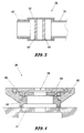
- the second light guide 26 is assembled to the hollow hole 44 for examining the specimen by the reflection method and includes, as shown in FIG. 3, a connection cylinder 48, peripheral surface thereof being screwed for being threaded to the beam splitter case through the hollow hole 44; a polarizer 50; a lens 49; and a rotatable cylinder 52, on which the polarizer 50 and the lens 49 are fixedly mounted, rotatably fitted to the connection cylinder 48, as a result, the polarizer being rotated in accordance with the rotation of the rotatable cylinder 52.
- a light is transmitted from a light source (not shown) to the lens 49 for collecting the light and the light is partially polarized in the polarizer 50, then is transmitted to the beam splitter 42.
- the stage 28 has a structure that a polarizer and a first light guide are provided in the central part of the stage and can rotate the polarizer.
- the light from the first light guide is partially polarized in the polarizer, then is transmitted to the lens assembly 24.
- the stage 28 includes a spacer 56 fixedly mounted on the base 12 and having a hollow hole at the central part of the spacer; a lower plate 60 fixedly mounted on the spacer 56 and having a hollow hole at the central part of the lower plate; a polarizer 58 placed on the lower plate 60 and at the central part of the stage; a rotatable plate 62 covering the outer surfaces of the spacer 56 and the lower plate 60 and rotatably mounted on the spacer 56 and the lower plate 60; and an upper plate 64 fixedly mounted on the rotatable plate 62, having a hollow hole at the central part of the upper plate and the polarizer 58 being fixedly mounted on the central part of the upper plate.
- the polarizer 58 rotates as the rotatable plate 62 is rotated.
- the first light guide 66 for the transmission method and a reflector 68 are provided.
- the light guide 66 is also connected to a light source (not shown) and transmits the light from the light source to the polarizer 58.
- the polarized light in the polarizer 50 is reflected to the specimen by the beam splitter 42.
- the light from the first light guide 66 in the base 12 is transmitted to the polarizer 58 to partially polarize the light. Then the light passes through the specimen.
- the light polarized by the above transmission method or reflection method is picked up by the objective 40 and is transmitted through the analyzer 39 and the compensating plate 41 to the CCD 22.
- a user can examine the specimen by the transmission method and/or reflection method and can handle the polarizer and the analyzer easily by rotating the rotatable plate and the rotatable cylinder, respectively.
Landscapes
- Physics & Mathematics (AREA)
- General Physics & Mathematics (AREA)
- Optics & Photonics (AREA)
- Chemical & Material Sciences (AREA)
- Analytical Chemistry (AREA)
- Engineering & Computer Science (AREA)
- Multimedia (AREA)
- Microscoopes, Condenser (AREA)
Applications Claiming Priority (2)
| Application Number | Priority Date | Filing Date | Title |
|---|---|---|---|
| KR9433174 | 1994-12-07 | ||
| KR1019940033174A KR100272329B1 (ko) | 1994-12-07 | 1994-12-07 | 비디오 마이크로스코프 |
Publications (1)
| Publication Number | Publication Date |
|---|---|
| EP0720036A1 true EP0720036A1 (de) | 1996-07-03 |
Family
ID=19400625
Family Applications (1)
| Application Number | Title | Priority Date | Filing Date |
|---|---|---|---|
| EP95308859A Withdrawn EP0720036A1 (de) | 1994-12-07 | 1995-12-06 | Videomikroskop |
Country Status (6)
| Country | Link |
|---|---|
| US (1) | US5691840A (de) |
| EP (1) | EP0720036A1 (de) |
| JP (1) | JPH08234112A (de) |
| KR (1) | KR100272329B1 (de) |
| CN (1) | CN1132358A (de) |
| TW (1) | TW336280B (de) |
Cited By (3)
| Publication number | Priority date | Publication date | Assignee | Title |
|---|---|---|---|---|
| EP1159640A4 (de) * | 1998-12-14 | 2003-01-22 | Sensir Technologies Llc | Miniaturisiertes opto-elektronisches vergrösserungssystem |
| WO2006126051A1 (en) * | 2005-05-25 | 2006-11-30 | Areva Np | Method for measuring the anisotropy in an element comprising at least one fissile material and a corresponding installation. |
| FR2886404A1 (fr) * | 2005-05-25 | 2006-12-01 | Framatome Anp Sas | Procede de mesure de l'anisotropie dans un element comprenant au moins un materiau fissile et installation correspondante. |
Families Citing this family (18)
| Publication number | Priority date | Publication date | Assignee | Title |
|---|---|---|---|---|
| JPH1172717A (ja) * | 1997-08-29 | 1999-03-16 | Nikon Corp | 顕微鏡デジタル写真撮影システム |
| USD410661S (en) | 1997-11-07 | 1999-06-08 | Haag-Streit Ag | Slit lamp microscope |
| US6147797A (en) * | 1998-01-20 | 2000-11-14 | Ki Technology Co., Ltd. | Image processing system for use with a microscope employing a digital camera |
| JP4053653B2 (ja) * | 1998-04-21 | 2008-02-27 | 株式会社モリテックス | Ccdマイクロスコープ |
| US6233350B1 (en) | 1999-03-04 | 2001-05-15 | Materials Technologies Corporation | Apparatus for viewing and inspecting a surface area of an object |
| TW526928U (en) * | 2001-08-08 | 2003-04-01 | Mustek Systems Inc | Microscopic function expansion module of digital camera |
| US7139121B2 (en) * | 2004-06-18 | 2006-11-21 | Quickmate Company, Inc | Projection microscope |
| CN100399102C (zh) * | 2005-11-23 | 2008-07-02 | 佛山市吉茂工业自动化技术有限公司 | 用于影像测量系统中的摄像机和显微镜的固定调整装置 |
| CN100398978C (zh) * | 2005-11-23 | 2008-07-02 | 佛山市吉茂工业自动化技术有限公司 | 一种手动影像测量仪 |
| DE102007027084B4 (de) * | 2007-06-12 | 2021-01-14 | Carl Zeiss Microscopy Gmbh | Mikroskop für die Beobachtung einer Probe im Hellfeld-Durchlicht- oder im Fluoreszenz-Auflicht-Kontrastverfahren |
| JP2009216825A (ja) * | 2008-03-07 | 2009-09-24 | Olympus Corp | 顕微鏡システム |
| USD660894S1 (en) * | 2010-08-26 | 2012-05-29 | Nikon Corporation | Support stand for a digital microscope |
| USD656977S1 (en) * | 2010-08-26 | 2012-04-03 | Nikon Corporation | Support stand for a digital microscope |
| DE102011108553B4 (de) * | 2011-07-22 | 2021-05-06 | Carl Zeiss Microscopy Gmbh | Anordnung zur Einstellung von Beleuchtungseinrichtungen an Durchlichtmikroskopen |
| USD706847S1 (en) * | 2013-01-09 | 2014-06-10 | Mitutoyo Corporation | Microscope |
| CN104931416A (zh) * | 2015-06-01 | 2015-09-23 | 安徽禄讯电子科技有限公司 | 一种高发光强度光源显微镜及图像鉴别分析装置和应用 |
| CN111474173B (zh) * | 2020-04-26 | 2022-12-16 | 山东省地质矿产勘查开发局第一地质大队 | 岩石中透明矿物突起等级的确定方法、系统及应用 |
| USD1009113S1 (en) * | 2021-05-25 | 2023-12-26 | Mitutoyo Corporation | Microscope unit |
Citations (3)
| Publication number | Priority date | Publication date | Assignee | Title |
|---|---|---|---|---|
| US3972619A (en) * | 1975-08-11 | 1976-08-03 | General Atomic Company | Method and apparatus for surface analysis |
| DE3148858A1 (de) * | 1981-07-13 | 1983-01-27 | Hamamatsu Systems Inc., 02154 Waltham, Mass. | Verfahren zum einstellen optimaler abbildungsbedingungen bei einer polarisations- oder interferenz-mikrofernseheinrichtung |
| US5386317A (en) * | 1992-05-13 | 1995-01-31 | Prometrix Corporation | Method and apparatus for imaging dense linewidth features using an optical microscope |
Family Cites Families (2)
| Publication number | Priority date | Publication date | Assignee | Title |
|---|---|---|---|---|
| JPS5632116A (en) * | 1979-08-23 | 1981-04-01 | Toshiba Corp | Specimen observing device |
| US5559630A (en) * | 1992-09-10 | 1996-09-24 | The Open University | Polarized light microscopy |
-
1994
- 1994-12-07 KR KR1019940033174A patent/KR100272329B1/ko not_active Expired - Fee Related
-
1995
- 1995-11-08 US US08/555,113 patent/US5691840A/en not_active Expired - Fee Related
- 1995-11-10 TW TW084111922A patent/TW336280B/zh active
- 1995-11-21 CN CN95119752A patent/CN1132358A/zh active Pending
- 1995-12-06 EP EP95308859A patent/EP0720036A1/de not_active Withdrawn
- 1995-12-07 JP JP7345282A patent/JPH08234112A/ja active Pending
Patent Citations (3)
| Publication number | Priority date | Publication date | Assignee | Title |
|---|---|---|---|---|
| US3972619A (en) * | 1975-08-11 | 1976-08-03 | General Atomic Company | Method and apparatus for surface analysis |
| DE3148858A1 (de) * | 1981-07-13 | 1983-01-27 | Hamamatsu Systems Inc., 02154 Waltham, Mass. | Verfahren zum einstellen optimaler abbildungsbedingungen bei einer polarisations- oder interferenz-mikrofernseheinrichtung |
| US5386317A (en) * | 1992-05-13 | 1995-01-31 | Prometrix Corporation | Method and apparatus for imaging dense linewidth features using an optical microscope |
Cited By (4)
| Publication number | Priority date | Publication date | Assignee | Title |
|---|---|---|---|---|
| EP1159640A4 (de) * | 1998-12-14 | 2003-01-22 | Sensir Technologies Llc | Miniaturisiertes opto-elektronisches vergrösserungssystem |
| WO2006126051A1 (en) * | 2005-05-25 | 2006-11-30 | Areva Np | Method for measuring the anisotropy in an element comprising at least one fissile material and a corresponding installation. |
| FR2886404A1 (fr) * | 2005-05-25 | 2006-12-01 | Framatome Anp Sas | Procede de mesure de l'anisotropie dans un element comprenant au moins un materiau fissile et installation correspondante. |
| US7982877B2 (en) | 2005-05-25 | 2011-07-19 | Areva Np | Method for measuring the anisotropy in an element comprising at least one fissile material and a corresponding installation |
Also Published As
| Publication number | Publication date |
|---|---|
| US5691840A (en) | 1997-11-25 |
| TW336280B (en) | 1998-07-11 |
| CN1132358A (zh) | 1996-10-02 |
| KR100272329B1 (ko) | 2000-11-15 |
| JPH08234112A (ja) | 1996-09-13 |
| KR960024490A (ko) | 1996-07-20 |
Similar Documents
| Publication | Publication Date | Title |
|---|---|---|
| US5691840A (en) | Video microscope | |
| US6414805B1 (en) | Reflected-light type fluorescence microscope and filter cassette used therefor | |
| JPH0129020B2 (de) | ||
| JPH0797078B2 (ja) | 赤外線顕微分光測定装置 | |
| JPH1073769A (ja) | 傾斜照明を伴う観察装置 | |
| JP3523348B2 (ja) | 細隙灯顕微鏡 | |
| US5144478A (en) | Microscope including first and second stages in conjugate planes | |
| US6396532B1 (en) | Computer controlled video microscopy system | |
| US4206966A (en) | Projection microscope with film holder | |
| US20090015912A1 (en) | Total Internal Reflectance Fluorescence (TIRF) Microscope | |
| JP3613402B2 (ja) | 光学顕微鏡を用いて緻密なライン幅構造を映像化する方法及び装置 | |
| JP2011027906A (ja) | 顕微鏡 | |
| WO2022097104A1 (en) | Digitization module for microscopes to enable sample viewing on a smart device | |
| US5305090A (en) | Birefringent inspection polarscope | |
| US5308983A (en) | Spectroscopic accessory with microscope illuminator | |
| JP2001174708A (ja) | 赤外顕微鏡 | |
| CN116184646A (zh) | 一种具有明暗视场切换功能的金相显微镜 | |
| JP3179136B2 (ja) | 顕微赤外atr測定装置 | |
| JP2002350740A (ja) | 顕微鏡用カメラアダプタ | |
| JP2000121553A (ja) | 赤外顕微鏡 | |
| JP2005031204A (ja) | 偏光顕微鏡および調整方法 | |
| JP4819989B2 (ja) | 顕微鏡 | |
| JP4300601B2 (ja) | 双眼顕微鏡と双眼顕微鏡による撮像方法 | |
| JP2002311333A (ja) | 顕微鏡用光偏向ユニット、それを備えた落射投光管及び顕微鏡 | |
| JPH0618410A (ja) | 赤外顕微測定装置 |
Legal Events
| Date | Code | Title | Description |
|---|---|---|---|
| PUAI | Public reference made under article 153(3) epc to a published international application that has entered the european phase |
Free format text: ORIGINAL CODE: 0009012 |
|
| AK | Designated contracting states |
Kind code of ref document: A1 Designated state(s): DE GB NL |
|
| 17P | Request for examination filed |
Effective date: 19960531 |
|
| RAP1 | Party data changed (applicant data changed or rights of an application transferred) |
Owner name: SAMSUNG AEROSPACE INDUSTRIES, LTD. |
|
| STAA | Information on the status of an ep patent application or granted ep patent |
Free format text: STATUS: THE APPLICATION IS DEEMED TO BE WITHDRAWN |
|
| 18D | Application deemed to be withdrawn |
Effective date: 19990701 |