EP0720182A2 - Verbundisolator und dessen Herstellungsverfahren - Google Patents
Verbundisolator und dessen Herstellungsverfahren Download PDFInfo
- Publication number
- EP0720182A2 EP0720182A2 EP95303948A EP95303948A EP0720182A2 EP 0720182 A2 EP0720182 A2 EP 0720182A2 EP 95303948 A EP95303948 A EP 95303948A EP 95303948 A EP95303948 A EP 95303948A EP 0720182 A2 EP0720182 A2 EP 0720182A2
- Authority
- EP
- European Patent Office
- Prior art keywords
- core rod
- sheath
- molded
- molded portions
- portions
- Prior art date
- Legal status (The legal status is an assumption and is not a legal conclusion. Google has not performed a legal analysis and makes no representation as to the accuracy of the status listed.)
- Granted
Links
- 239000012212 insulator Substances 0.000 title claims abstract description 44
- 239000002131 composite material Substances 0.000 title claims abstract description 39
- 238000004519 manufacturing process Methods 0.000 title claims description 18
- 239000000463 material Substances 0.000 claims abstract description 34
- 239000011810 insulating material Substances 0.000 claims abstract description 33
- 238000000465 moulding Methods 0.000 claims abstract description 17
- 238000000034 method Methods 0.000 claims description 18
- 229920001971 elastomer Polymers 0.000 claims description 5
- 229920001187 thermosetting polymer Polymers 0.000 claims description 5
- 230000015572 biosynthetic process Effects 0.000 description 7
- 229920002430 Fibre-reinforced plastic Polymers 0.000 description 6
- 239000011151 fibre-reinforced plastic Substances 0.000 description 6
- 229920005989 resin Polymers 0.000 description 6
- 239000011347 resin Substances 0.000 description 6
- 239000002184 metal Substances 0.000 description 5
- 229920001577 copolymer Polymers 0.000 description 4
- 238000010438 heat treatment Methods 0.000 description 4
- 238000002347 injection Methods 0.000 description 4
- 239000007924 injection Substances 0.000 description 4
- 229920002379 silicone rubber Polymers 0.000 description 3
- 239000004945 silicone rubber Substances 0.000 description 3
- 230000002950 deficient Effects 0.000 description 2
- 238000001746 injection moulding Methods 0.000 description 2
- 229920001343 polytetrafluoroethylene Polymers 0.000 description 2
- 239000004810 polytetrafluoroethylene Substances 0.000 description 2
- 229920002635 polyurethane Polymers 0.000 description 2
- 239000004814 polyurethane Substances 0.000 description 2
- 230000004323 axial length Effects 0.000 description 1
- 238000010276 construction Methods 0.000 description 1
- 239000003822 epoxy resin Substances 0.000 description 1
- 229920001973 fluoroelastomer Polymers 0.000 description 1
- 238000011835 investigation Methods 0.000 description 1
- 238000012986 modification Methods 0.000 description 1
- 230000004048 modification Effects 0.000 description 1
- 229920000647 polyepoxide Polymers 0.000 description 1
- -1 polytetrafluoroethylene Polymers 0.000 description 1
- 239000002994 raw material Substances 0.000 description 1
- 239000000243 solution Substances 0.000 description 1
Images

Classifications
-
- H—ELECTRICITY
- H01—ELECTRIC ELEMENTS
- H01B—CABLES; CONDUCTORS; INSULATORS; SELECTION OF MATERIALS FOR THEIR CONDUCTIVE, INSULATING OR DIELECTRIC PROPERTIES
- H01B19/00—Apparatus or processes specially adapted for manufacturing insulators or insulating bodies
-
- B—PERFORMING OPERATIONS; TRANSPORTING
- B29—WORKING OF PLASTICS; WORKING OF SUBSTANCES IN A PLASTIC STATE IN GENERAL
- B29C—SHAPING OR JOINING OF PLASTICS; SHAPING OF MATERIAL IN A PLASTIC STATE, NOT OTHERWISE PROVIDED FOR; AFTER-TREATMENT OF THE SHAPED PRODUCTS, e.g. REPAIRING
- B29C33/00—Moulds or cores; Details thereof or accessories therefor
- B29C33/12—Moulds or cores; Details thereof or accessories therefor with incorporated means for positioning inserts, e.g. labels
- B29C33/123—Moulds or cores; Details thereof or accessories therefor with incorporated means for positioning inserts, e.g. labels for centering the inserts
-
- B—PERFORMING OPERATIONS; TRANSPORTING
- B29—WORKING OF PLASTICS; WORKING OF SUBSTANCES IN A PLASTIC STATE IN GENERAL
- B29C—SHAPING OR JOINING OF PLASTICS; SHAPING OF MATERIAL IN A PLASTIC STATE, NOT OTHERWISE PROVIDED FOR; AFTER-TREATMENT OF THE SHAPED PRODUCTS, e.g. REPAIRING
- B29C35/00—Heating, cooling or curing, e.g. crosslinking or vulcanising; Apparatus therefor
- B29C35/02—Heating or curing, e.g. crosslinking or vulcanizing during moulding, e.g. in a mould
- B29C35/0266—Local curing
-
- B—PERFORMING OPERATIONS; TRANSPORTING
- B29—WORKING OF PLASTICS; WORKING OF SUBSTANCES IN A PLASTIC STATE IN GENERAL
- B29C—SHAPING OR JOINING OF PLASTICS; SHAPING OF MATERIAL IN A PLASTIC STATE, NOT OTHERWISE PROVIDED FOR; AFTER-TREATMENT OF THE SHAPED PRODUCTS, e.g. REPAIRING
- B29C70/00—Shaping composites, i.e. plastics material comprising reinforcements, fillers or preformed parts, e.g. inserts
- B29C70/68—Shaping composites, i.e. plastics material comprising reinforcements, fillers or preformed parts, e.g. inserts by incorporating or moulding on preformed parts, e.g. inserts or layers, e.g. foam blocks
- B29C70/72—Encapsulating inserts having non-encapsulated projections, e.g. extremities or terminal portions of electrical components
-
- B—PERFORMING OPERATIONS; TRANSPORTING
- B29—WORKING OF PLASTICS; WORKING OF SUBSTANCES IN A PLASTIC STATE IN GENERAL
- B29C—SHAPING OR JOINING OF PLASTICS; SHAPING OF MATERIAL IN A PLASTIC STATE, NOT OTHERWISE PROVIDED FOR; AFTER-TREATMENT OF THE SHAPED PRODUCTS, e.g. REPAIRING
- B29C2791/00—Shaping characteristics in general
- B29C2791/001—Shaping in several steps
-
- B—PERFORMING OPERATIONS; TRANSPORTING
- B29—WORKING OF PLASTICS; WORKING OF SUBSTANCES IN A PLASTIC STATE IN GENERAL
- B29L—INDEXING SCHEME ASSOCIATED WITH SUBCLASS B29C, RELATING TO PARTICULAR ARTICLES
- B29L2031/00—Other particular articles
- B29L2031/34—Electrical apparatus, e.g. sparking plugs or parts thereof
- B29L2031/3412—Insulators
-
- Y—GENERAL TAGGING OF NEW TECHNOLOGICAL DEVELOPMENTS; GENERAL TAGGING OF CROSS-SECTIONAL TECHNOLOGIES SPANNING OVER SEVERAL SECTIONS OF THE IPC; TECHNICAL SUBJECTS COVERED BY FORMER USPC CROSS-REFERENCE ART COLLECTIONS [XRACs] AND DIGESTS
- Y10—TECHNICAL SUBJECTS COVERED BY FORMER USPC
- Y10T—TECHNICAL SUBJECTS COVERED BY FORMER US CLASSIFICATION
- Y10T428/00—Stock material or miscellaneous articles
- Y10T428/29—Coated or structually defined flake, particle, cell, strand, strand portion, rod, filament, macroscopic fiber or mass thereof
- Y10T428/2913—Rod, strand, filament or fiber
- Y10T428/2922—Nonlinear [e.g., crimped, coiled, etc.]
- Y10T428/2924—Composite
-
- Y—GENERAL TAGGING OF NEW TECHNOLOGICAL DEVELOPMENTS; GENERAL TAGGING OF CROSS-SECTIONAL TECHNOLOGIES SPANNING OVER SEVERAL SECTIONS OF THE IPC; TECHNICAL SUBJECTS COVERED BY FORMER USPC CROSS-REFERENCE ART COLLECTIONS [XRACs] AND DIGESTS
- Y10—TECHNICAL SUBJECTS COVERED BY FORMER USPC
- Y10T—TECHNICAL SUBJECTS COVERED BY FORMER US CLASSIFICATION
- Y10T428/00—Stock material or miscellaneous articles
- Y10T428/29—Coated or structually defined flake, particle, cell, strand, strand portion, rod, filament, macroscopic fiber or mass thereof
- Y10T428/2913—Rod, strand, filament or fiber
- Y10T428/2933—Coated or with bond, impregnation or core
Definitions
- the present invention relates to an elongate composite insulator which comprises an elongate core rod composed, e.g., of a fiber-reinforced plastics (FRP), a sheath which covers the core rod over substantially the entire length thereof, and a plurality of sheds which are formed on the sheath and spaced from each other in the axial direction of the core rod, wherein the sheath and the sheds are formed by integrally molding of an insulating polymeric material.
- FRP fiber-reinforced plastics
- the present invention also relates to a method for manufacturing such composite insulators.
- a composite insulator which can be obtained by integrally providing an elongate core rod of fiber-reinforced plastics (FRP) with a sheath and sheds by an injection molding of an appropriate insulating polymeric material such as silicone rubber, ethylene propylene copolymer (EPM), ethylene propylene diene copolymer (EPDM), polyurethane, etc.
- FRP fiber-reinforced plastics
- EPM ethylene propylene copolymer
- EPDM ethylene propylene diene copolymer
- polyurethane etc.
- Such a composite insulator has been actually put into practical applications, particularly in any use environment which can draw out various functional advantages of the composite insulator.
- various improvements have been conventionally proposed.
- JP-A-6-203680 discloses the applicant's earlier proposal wherein an axially continuous sheath of an elongate composite insulator is formed in a stepwise manner.
- a FRP core rod is placed only partly within a mold cavity of a molding machine, and a first molded portion corresponding to a part of the sheath and sheds is formed on that portion of the core rod which is situated within the mold cavity.
- the core rod is subsequently displaced in the axial direction by a predetermined amount relative to the mold and a second and succeeding molded portions are formed, which are similar to the first molded portion, with the respective molded portions being simultaneously integrated with each other so that an elongate composite insulator has an axially continuous sheath and associated sheds.
- an axially continuous sheath having a desired length is formed by integrating a plurality of molded portions which are succeedingly formed on the core rod in axial alignment with each other, it is possible to manufacture an elongate composite insulator having a high accuracy and an excellent insulating property, in a facilitated and simplified manner, without increasing the length of the mold.
- the molding machine capable of manufacturing elongate composite insulators includes an end forming member arranged in a rear end portion of a mold cavity, for forming a rear end of a molded portion which forms an integral part of the sheath.
- a space for accommodating a front end region of the molded portion is provided adjacent to a front end portion of the metal mold cavity.
- a first jig for forming a head portion of the sheath, and a second jig for positioning the core rod relative to the mold by clamping the front end of the molded portion can be selectively attached to and removed from the front end of the mold cavity.
- the second jig at the front end of the mold cavity may be composed of a set of arcuate or semi-circular segments which serve to prevent a leakage of the polymeric material which has been injected into the mold cavity.
- the first jig is attached to the front end portion of the mold cavity and a first molded portion having a head and a rear end is formed on the core rod.
- the core rod is then displaced in the axial direction and the first jig in the front end of the mold cavity is replaced by the second jig.
- the second molded portion is formed on the core rod with the rear end of the first molded portion clamped by the second jig and the core rod positioned relative to the mold.
- the second molded portion is formed with its front end tightly sealed to, and directly united with the rear end of the first molded portion. Therefore, even though the sheath and the sheds are molded as axially divided pieces, the adjacent molded portions are united with each other to provide an axially continuous sheath and an excellent insulating property of the composite insulator.
- the process for manufacturing the composite insulators according to the applicant's earlier proposal proved to be highly advantageous in that elongate products with a high accuracy and an excellent insulating property can be produced in a facilitated and simplified manner, without increasing the length of the mold, under appropriately adjusted mold conditions. Still, it would be desirable to enable a more reliable manufacture of the composite insulator having a further improved product quality, while maintaining the advantage of the earlier proposal.
- the inventors also found that, in order to constantly enable production of composite insulators having a satisfactory quality without involving the above-mentioned difficulties, it would be effective to ensure that the injection pressure during formation of a succeeding molded portion is not directly applied to the rear end of the preceding molded portion and, in particular, to integrate the adjacent molded portions after the molding process.
- the present invention in its first aspect provides an improved composite insulator which comprises a core rod, a sheath which covers the core rod over substantially the entire length thereof, and a plurality of sheds which are formed on the sheath and spaced from each other in the axial direction of the core rod, wherein the sheath and the sheds are formed on the core rod by integrally molding an insulating polymeric material, and the sheath is comprised of a plurality of molded portions which are aligned with each other in the axial direction of the core rod.
- adjacent molded portions of the sheath are provided with opposite ends which are arranged relative to each other so as to leave a predetermined gap therebetween, and the gap is filled by a joint insulating material which is integrally united to the polymeric material of the adjacent molded portions.
- the present invention in its second aspect provides an improved method for manufacturing a composite insulator which comprises a core rod, a sheath which covers the core rod over substantially the entire length thereof, and a plurality of sheds which are formed on the sheath and spaced from each other in the axial direction of the core rod, wherein the sheath and the sheds are formed on the core rod by integrally molding an insulating polymeric material, and the sheath is comprised of a plurality of molded portions which are aligned with each other in the axial direction of the core rod.
- the method according to the present invention comprises the steps of (i) forming a first molded portion of the sheath on the core rod and subsequently forming a second molded portion of the sheath on the core rod adjacent to the first molded portion so that a predetermined gap is left between opposite ends of the first and second molded portions of the sheath, and (ii) filling a joint insulating material in the gap between the opposite ends of the adjacent molded portions, and integrally uniting the joint insulating material with the polymeric material of the adjacent molded portions.
- the sheath which covers the core rod over substantially the entire length thereof is formed by successively forming a plurality of molded portions in alignment with each other in the axial direction of the core rod, with a gap left between opposite ends of the adjacent molded portions, and subsequently integrating the molded portions by filling a joint insulating material in the gap. Therefore, the injection pressure is not directly applied to the rear end of the preceding molded portion when forming the succeeding molded portions among a plurality of the molded portions forming the sheath.
- the present invention thus makes it possible to positively prevent occurrence of deformation, peeling-off or cracks of the molded portion during formation of the succeeding molded portions, and the leakage of the polymeric material in the front end portion of the mold cavity, thereby effectively avoiding occurrence of defective products due to adhesion of the leaked polymeric material to the outer surface of the molded product.
- the composite insulator 10 includes an elongate core rod 11, a sheath 12 which covers the core rod 11 over substantially the entire length thereof, and a plurality of sheds 13 which are formed on the sheath and spaced from each other in the axial direction of the core rod 11.
- the core rod 11 consists of fiber-reinforced plastics or appropriate thermosetting resin such as epoxy resin.
- the sheath 12 and the sheds 13 are integral formed by molding appropriate insulating polymeric material, such as silicone rubber, ethylene propylene copolymer (EPM), ethylene propylene diene copolymer (EPDM) or polyurethane.
- the sheath 12 is comprised of a plurality of molded portions 12a and 12b which are continuously aligned in the axial direction of the core rod 11.
- Metal fittings (not shown) are fixedly secured to both end portions of the core rod 11 in a manner known, per se..
- opposite ends of adjacent molded portions 12a and 12b of the sheath 12 i.e., the right end of the molded portion 12a shown on the left side in Fig. 1 and the left end of the molded portion 12b shown on the right side in Fig. 1, are arranged relative to each other so as to leave an annular gap therebetween.
- a joint insulating material 14 is filled in the gap between the opposite ends of the adjacent molded portions 12a and 12b over the entire circumference of the gap, and the joint insulating material 14 is integrally united with the resin forming the molded portions 12a and 12b.
- the opposite ends of the adjacent molded portions 12a and 12b of the sheath 12 prefferably have slant surfaces which form a predetermined angle ⁇ with respect to the center axis of the core rod 11, e.g., approximately 60°.
- ⁇ a predetermined angle
- the opposite ends of the adjacent molded portions 12a and 12b of the sheath 12 are spaced from each other by an axial distance which gradually increases radially outwardly of the insulator 10.
- the adjacent molded portions 12a and 12b are integrated with each other through the joint insulating material 14, it is possible to assure the continuity of the sheath 11 and thereby realize an excellent insulating property of the insulator 10 as a whole. Furthermore, according to the present invention, the molded portions 12a and 12b are successively formed in alignment with each other in the axial direction of the long core rod 11, and subsequently integrated with each other so as to stepwisely form an elongate and yet continuous sheath 12 with a predetermined length, as will be more fully explained hereinafter. Therefore, it is possible to manufacture elongate composite insulators having high accuracy and excellent properties, in a facilitated and simplified manner, without increasing the length of the mold of the molding machine.
- an apparatus which can be suitably used for manufacturing the composite insulator 10 according to the present invention comprises a molding machine which includes a mold 20 having the basic configuration similar to that disclosed in the above-mentioned JP-A-6-203680.
- the mold 20 has an inner surface defining a mold cavity 21 of a shape which corresponds to the sheath 12 and the sheds 13 on the core rod 11.
- the mold 20 serves to successively form the molded portions 12a and 12b corresponding to the sheath 12 and the sheds 13 associated with the respective molded portions 12a and 12b, by injecting an insulating polymeric material (such as silicone rubber) into the cavity 21, with the core rod 11 positioned at a predetermined axial location with respect to the cavity 21.
- an insulating polymeric material such as silicone rubber
- the mold cavity 21 has a rear end portion (the right end portion in the drawing) which is provided with an annular ring 22 as a rear end forming member for forming the rear ends of the molded portions 12a and 12b corresponding to the sheath 12.
- the annular ring 22 has an inner periphery which is provided with a seal ring 23 for preventing leakage of the polymeric material through a gap between the ring 22 and the core rod 11.
- a seal ring 23 for preventing leakage of the polymeric material through a gap between the ring 22 and the core rod 11.
- the mold cavity 21 has a front end portion (the left end portion in the drawing) which is provided with an annular ring 24 as a front end forming member for forming the front ends of the molded portions 12a and 12b or the head portion of the sheath 12 when the molded portion 12a is the first and foremost molded portion.
- the annular ring 24 has an inner periphery which is provided with a seal ring 25 for preventing leakage of the polymeric material through a gap between the ring 24 and the core rod 11.
- a space 26 is provided adjacent to the front end portion of the mold cavity 21, for accommodating the rear end of a preceding molded portion 12a and 12b when the core rod 11 is displaced in the axial direction with respect to the cavity 21.
- the annular rings 22 and 24 at the both end portions of the mold cavity 21 may have a split structure, each constituted by a pair of semi-circular segments.
- the seal rings 23 and 25 for such annular rings 22 and 24 may be comprised, e.g., of polytetrafluoroethylene (PTFE) and may have a similar split structure.
- the annular ring 22 for the rear end portion of the mold cavity 21 may have an integral construction, and combined with a seal ring 23 which is comprised, e.g., of a heat resistant fluoro rubber.
- the composite insulator 10 according to the present invention can be produced by stepwisely forming the sheath 12 and the sheds 13 on the core rod 11 in the following manner.
- the annular rings 22 and 24 are fastened to the core rod 11 at the front and rear end portions of the cavity 21 with the mold 20 opened.
- the core rod 11 is positioned at a predetermined axial location with respect to the cavity 21, and the mold 20 is then closed in a manner known, per se.
- the insulating polymeric material is injected into the cavity 21 from gates (not shown) of the mold 20 which are situated at locations corresponding, e.g., to the rear surfaces of the sheds 13 of the insulator 10.
- the polymeric material injected into the cavity 21 is cured.
- the foremost molded portion 12a and the sheds 13 associated therewith are integrally formed on the core rod 11.
- the metal mold 20 is opened in a second step, and the annular rings 22 and 24 at the front and rear end portions of the cavity 21 are loosened.
- the core rod 11 then is displaced in the axial direction toward left in the drawing, by a predetermined amount with respect to the cavity 21.
- the annular rings 22 and 24 are then fastened to the core rod 11 in such a new relative position and the metal mold 20 is closed.
- the foremost molded portion 12a and the shed portions 13 associated with that molded portion 12a which have already been formed in the first step, are accommodated in the space 26 having each ends situated adjacent to the front end portion of the cavity 21.
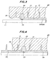
- the second molded portion 12b formed as above has a front end which is as shown in Fig. 4, and a rear end which is similar to that of the foremost molded portion 12a shown in Fig. 2.
- the second step may be repeated, if necessary, to sequentially form a predetermined number of the successive molded portions on the core rod 11, corresponding to the full length of the insulator to be produced.
- the core rod 11, which has been sequentially formed with a predetermined number of the molded portions 12a and 12b is removed from the mold 20.
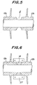
- the rear end of the preceding molded portion 12a is axially spaced from the front end of the succeeding molded portion 12b adjacent thereto, by a distance which corresponds to the thickness of the annular ring 24 situated at the front end portion of the mold cavity 21. Therefore, a gap G is left between the opposite ends of the adjacent molded portions 12a and 12b. It is in many cases desirable to gradually increase the axial length of the gap G, i.e., the axial distance between the opposite ends, radially outwardly of the insulator 10, as described above.
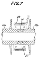
- An annular jig 27 is fitted to surround the outer periphery of the joint insulating material 14, bridging between the opposite ends of the molded portions 12a and 12b as shown in Fig. 6.
- the jig 27 may be comprised of a pair of semi-circular segments, like the annular rings 22 and 24. Furthermore, as shown in Fig.
- the band heater 28 is supplied with electric current to carry out a resistance heating of the joint insulating material 14 for a predetermined time.
- the joint insulating material 14 is the unvulcanized rubber
- the joint insulating material 14 is vulcanized by the heating.
- the joint insulating material 14 is a thermosetting resin
- the joint insulating material 14 is cured by the heating. As a result, the joint insulating material 14 is completely united with the polymeric material forming the adjacent molded portions 12a and 12b.
- the composite insulator 10 shown in Fig. 1 can be obtained by removing the band heater 28 and the annular jig 27 from the joint insulating material 14.
- the sheath which covers the core rod over substantially the entire length thereof is formed by succeedingly forming adjacent molded portions in alignment with each other in the axial direction of the core rod, with a gap left between opposite ends of the molded portions, and the molded portions are integrated by filling a joint insulating material in the gap so as to integrate the adjacent molded portions. Therefore, the injection pressure is not directly applied to the rear end of the preceding molded portion when forming the succeeding molded portions among a plurality of the molded portions forming the sheath.
- the present invention thus makes it possible to positively prevent occurrence of deformation, peeling-off or cracks of the molded portion during formation of the succeeding molded portions, and the leakage of the polymeric material in the front end portion of the mold cavity, thereby effectively avoiding occurrence of defective products due to adhesion of the leaked polymeric material to the outer surface of the molded product.
- the joint insulating material may be heated and integrally united with the polymeric material of the molded portions, by placing the entire core rod in an appropriate furnace, instead of employing the band heater as shown in Fig. 7.
Landscapes
- Engineering & Computer Science (AREA)
- Mechanical Engineering (AREA)
- Physics & Mathematics (AREA)
- Health & Medical Sciences (AREA)
- Oral & Maxillofacial Surgery (AREA)
- Thermal Sciences (AREA)
- Chemical & Material Sciences (AREA)
- Composite Materials (AREA)
- Insulators (AREA)
- Insulating Bodies (AREA)
Applications Claiming Priority (3)
| Application Number | Priority Date | Filing Date | Title |
|---|---|---|---|
| JP6325465A JP2824025B2 (ja) | 1994-12-27 | 1994-12-27 | 複合碍子およびその製造方法 |
| JP325465/94 | 1994-12-27 | ||
| JP32546594 | 1994-12-27 |
Publications (3)
| Publication Number | Publication Date |
|---|---|
| EP0720182A2 true EP0720182A2 (de) | 1996-07-03 |
| EP0720182A3 EP0720182A3 (de) | 1997-02-12 |
| EP0720182B1 EP0720182B1 (de) | 2000-01-26 |
Family
ID=18177180
Family Applications (1)
| Application Number | Title | Priority Date | Filing Date |
|---|---|---|---|
| EP95303948A Expired - Lifetime EP0720182B1 (de) | 1994-12-27 | 1995-06-08 | Verbundisolator und dessen Herstellungsverfahren |
Country Status (5)
| Country | Link |
|---|---|
| US (1) | US5540991A (de) |
| EP (1) | EP0720182B1 (de) |
| JP (1) | JP2824025B2 (de) |
| CA (1) | CA2151352C (de) |
| DE (1) | DE69514770T2 (de) |
Cited By (2)
| Publication number | Priority date | Publication date | Assignee | Title |
|---|---|---|---|---|
| EP0796722A3 (de) * | 1996-03-18 | 2000-02-09 | Ngk Insulators, Ltd. | Verfahren zur Herstellung eines Verbundisolators |
| FR2785142A1 (fr) * | 1998-04-22 | 2000-04-28 | Siemens Ag | Composant electrotechnique a surface passivee par de la matiere plastique et utilisation de ce composant |
Families Citing this family (12)
| Publication number | Priority date | Publication date | Assignee | Title |
|---|---|---|---|---|
| DE69709459T2 (de) * | 1996-07-31 | 2002-09-05 | Pirelli Cavi E Sistemi S.P.A., Mailand/Milano | Verfahren zur Herstellung eines isolierenden Überzugs mit schirmförmigem Profil |
| US5877453A (en) * | 1997-09-17 | 1999-03-02 | Maclean-Fogg Company | Composite insulator |
| CA2349253C (en) | 2000-12-26 | 2009-11-17 | S&C Electric Company | Method and arrangement for providing a gas-tight housing joint |
| US7044458B2 (en) | 2001-04-30 | 2006-05-16 | Maclean-Fogg Company | Stabilizer bar |
| US6831232B2 (en) * | 2002-06-16 | 2004-12-14 | Scott Henricks | Composite insulator |
| US6952154B2 (en) * | 2002-06-16 | 2005-10-04 | Maclean-Fogg Company | Composite insulator for fuse cutout |
| WO2008104614A1 (es) * | 2007-02-28 | 2008-09-04 | Airbus España, S.L. | Utillaje y método de fabricación de cuadernas de aeronave en material compuesto |
| US7646282B2 (en) * | 2007-12-14 | 2010-01-12 | Jiri Pazdirek | Insulator for cutout switch and fuse assembly |
| US8729396B2 (en) | 2010-09-02 | 2014-05-20 | Cooper Technologies Company | Full composite insulator for electrical cutout |
| CN102809051B (zh) * | 2012-08-07 | 2015-05-06 | 西安康本材料有限公司 | 适用于螺旋键连接的复合材料管及其制作方法 |
| DE102017214120A1 (de) * | 2017-08-11 | 2019-02-14 | Lapp Insulators Gmbh | Verbundisolator sowie Verfahren zum Herstellen eines Verbundisolators |
| US11581111B2 (en) * | 2020-08-20 | 2023-02-14 | Te Connectivity Solutions Gmbh | Composite polymer insulators and methods for forming same |
Citations (2)
| Publication number | Priority date | Publication date | Assignee | Title |
|---|---|---|---|---|
| JPS60500929A (ja) | 1983-03-25 | 1985-06-20 | セラヴエ−ル | 非常な長さの有機電気絶縁体の絶縁被覆の成型法及びこの方法により得られる電気絶縁体 |
| JPH06203680A (ja) | 1992-12-28 | 1994-07-22 | Ngk Insulators Ltd | ノンセラミック碍子の成形方法及び成形装置 |
Family Cites Families (5)
| Publication number | Priority date | Publication date | Assignee | Title |
|---|---|---|---|---|
| DE2511809A1 (de) * | 1975-03-18 | 1976-09-30 | Rhein Westfael Isolatoren | Haenge-isolator |
| DE2742042A1 (de) * | 1977-09-19 | 1979-03-29 | Siemens Ag | Verfahren zur herstellung von kunststoffisolierkoerpern mit schirmen fuer den innenraum- und freilufteinsatz |
| WO1980001621A1 (fr) * | 1979-01-27 | 1980-08-07 | Bbc Brown Boveri & Cie | Isolateur composite pour haute tension |
| FR2461343A1 (fr) * | 1979-07-11 | 1981-01-30 | Ceraver | Element isolant a ailettes ou groupes monoblocs d'ailettes vulcanisees disposees bout a bout |
| JPS6255247A (ja) * | 1985-09-05 | 1987-03-10 | Nippon Denso Co Ltd | 車両用エアコンデイシヨナのための曇除去装置 |
-
1994
- 1994-12-27 JP JP6325465A patent/JP2824025B2/ja not_active Expired - Lifetime
-
1995
- 1995-06-07 US US08/487,554 patent/US5540991A/en not_active Expired - Fee Related
- 1995-06-08 DE DE69514770T patent/DE69514770T2/de not_active Expired - Fee Related
- 1995-06-08 CA CA002151352A patent/CA2151352C/en not_active Expired - Fee Related
- 1995-06-08 EP EP95303948A patent/EP0720182B1/de not_active Expired - Lifetime
Patent Citations (2)
| Publication number | Priority date | Publication date | Assignee | Title |
|---|---|---|---|---|
| JPS60500929A (ja) | 1983-03-25 | 1985-06-20 | セラヴエ−ル | 非常な長さの有機電気絶縁体の絶縁被覆の成型法及びこの方法により得られる電気絶縁体 |
| JPH06203680A (ja) | 1992-12-28 | 1994-07-22 | Ngk Insulators Ltd | ノンセラミック碍子の成形方法及び成形装置 |
Cited By (3)
| Publication number | Priority date | Publication date | Assignee | Title |
|---|---|---|---|---|
| EP0796722A3 (de) * | 1996-03-18 | 2000-02-09 | Ngk Insulators, Ltd. | Verfahren zur Herstellung eines Verbundisolators |
| FR2785142A1 (fr) * | 1998-04-22 | 2000-04-28 | Siemens Ag | Composant electrotechnique a surface passivee par de la matiere plastique et utilisation de ce composant |
| US7024737B2 (en) | 1998-04-22 | 2006-04-11 | Siemens Aktiengesellschaft | Method for producing an electronic or electrical component with a plastic-passivated surface |
Also Published As
| Publication number | Publication date |
|---|---|
| JPH08185740A (ja) | 1996-07-16 |
| DE69514770T2 (de) | 2000-06-29 |
| DE69514770D1 (de) | 2000-03-02 |
| EP0720182B1 (de) | 2000-01-26 |
| JP2824025B2 (ja) | 1998-11-11 |
| US5540991A (en) | 1996-07-30 |
| CA2151352A1 (en) | 1996-06-28 |
| CA2151352C (en) | 1998-04-28 |
| EP0720182A3 (de) | 1997-02-12 |
Similar Documents
| Publication | Publication Date | Title |
|---|---|---|
| US5540991A (en) | Composite insulator and its manufacturing method | |
| US4702873A (en) | Method of manufacturing a composite insulator | |
| EP0624446B1 (de) | Verfahren und Vorrichtung zum Herstellen von Isolatoren | |
| US5612069A (en) | Apparatus for manufacturing a long non-ceramic insulator in a mold longitudinally shorter than the insulator | |
| US4234368A (en) | Method of making a pipe coupling | |
| CA1069152A (en) | Manufacture of pipe couplings | |
| FI83486B (fi) | Foerfarande foer framstaellning av ett speciellt i roerskarvar anvaendbart taetningsstycke och form foer framstaellning av taetningsstycket. | |
| US5811049A (en) | Method for producing composite insulator | |
| JPS61181015A (ja) | 耐高電圧性部材の製造方法 | |
| US4377547A (en) | Molded high voltage splice body | |
| EP3650190B1 (de) | Montagewerkzeug | |
| US20040209025A1 (en) | Cold-shrinkable type rubber sleeve and method of manufacturing the same | |
| US4711086A (en) | Trident II first and second stage internal insulation | |
| US20070039692A1 (en) | Cold-shrinkable type rubber insulation sleeve and method of manufacturing | |
| JPH08227626A (ja) | 碍子とその製造方法 | |
| US5753272A (en) | Apparatus for manufacturing composite insulators | |
| CS708888A3 (en) | Casting accessories for producing cast stock from plastic | |
| US11581111B2 (en) | Composite polymer insulators and methods for forming same | |
| CA1172821A (en) | Process of and device for continuous vulcanization of reinforced elastomeric hose | |
| KR100615814B1 (ko) | 고분자 애자 제조방법 | |
| US4932637A (en) | Hydrostatically compressed elastomeric spring and its manufacturing method | |
| JP2900096B2 (ja) | ゴム,プラスチック成形体の製造方法 | |
| JP2002369365A (ja) | 電力ケーブル接続用高分子材料製筒状部材の製造方法 | |
| JPH08185749A (ja) | 金型を用いた複合碍子の製造方法 | |
| JPH09103015A (ja) | Cvケーブルの絶縁接続方法 |
Legal Events
| Date | Code | Title | Description |
|---|---|---|---|
| PUAI | Public reference made under article 153(3) epc to a published international application that has entered the european phase |
Free format text: ORIGINAL CODE: 0009012 |
|
| AK | Designated contracting states |
Kind code of ref document: A2 Designated state(s): DE FR GB |
|
| PUAL | Search report despatched |
Free format text: ORIGINAL CODE: 0009013 |
|
| AK | Designated contracting states |
Kind code of ref document: A3 Designated state(s): DE FR GB |
|
| 17P | Request for examination filed |
Effective date: 19970605 |
|
| 17Q | First examination report despatched |
Effective date: 19980805 |
|
| GRAG | Despatch of communication of intention to grant |
Free format text: ORIGINAL CODE: EPIDOS AGRA |
|
| GRAG | Despatch of communication of intention to grant |
Free format text: ORIGINAL CODE: EPIDOS AGRA |
|
| GRAH | Despatch of communication of intention to grant a patent |
Free format text: ORIGINAL CODE: EPIDOS IGRA |
|
| GRAH | Despatch of communication of intention to grant a patent |
Free format text: ORIGINAL CODE: EPIDOS IGRA |
|
| GRAA | (expected) grant |
Free format text: ORIGINAL CODE: 0009210 |
|
| AK | Designated contracting states |
Kind code of ref document: B1 Designated state(s): DE FR GB |
|
| REF | Corresponds to: |
Ref document number: 69514770 Country of ref document: DE Date of ref document: 20000302 |
|
| ET | Fr: translation filed | ||
| PLBE | No opposition filed within time limit |
Free format text: ORIGINAL CODE: 0009261 |
|
| STAA | Information on the status of an ep patent application or granted ep patent |
Free format text: STATUS: NO OPPOSITION FILED WITHIN TIME LIMIT |
|
| 26N | No opposition filed | ||
| PGFP | Annual fee paid to national office [announced via postgrant information from national office to epo] |
Ref country code: GB Payment date: 20010529 Year of fee payment: 7 |
|
| PGFP | Annual fee paid to national office [announced via postgrant information from national office to epo] |
Ref country code: FR Payment date: 20010620 Year of fee payment: 7 |
|
| PGFP | Annual fee paid to national office [announced via postgrant information from national office to epo] |
Ref country code: DE Payment date: 20010623 Year of fee payment: 7 |
|
| REG | Reference to a national code |
Ref country code: GB Ref legal event code: IF02 |
|
| PG25 | Lapsed in a contracting state [announced via postgrant information from national office to epo] |
Ref country code: GB Free format text: LAPSE BECAUSE OF NON-PAYMENT OF DUE FEES Effective date: 20020608 |
|
| PG25 | Lapsed in a contracting state [announced via postgrant information from national office to epo] |
Ref country code: DE Free format text: LAPSE BECAUSE OF NON-PAYMENT OF DUE FEES Effective date: 20030101 |
|
| GBPC | Gb: european patent ceased through non-payment of renewal fee |
Effective date: 20020608 |
|
| PG25 | Lapsed in a contracting state [announced via postgrant information from national office to epo] |
Ref country code: FR Free format text: LAPSE BECAUSE OF NON-PAYMENT OF DUE FEES Effective date: 20030228 |
|
| REG | Reference to a national code |
Ref country code: FR Ref legal event code: ST |