EP0720251A2 - Automatisch versenkbare Funkantenne für Kraftfahrzeuge - Google Patents
Automatisch versenkbare Funkantenne für Kraftfahrzeuge Download PDFInfo
- Publication number
- EP0720251A2 EP0720251A2 EP95120231A EP95120231A EP0720251A2 EP 0720251 A2 EP0720251 A2 EP 0720251A2 EP 95120231 A EP95120231 A EP 95120231A EP 95120231 A EP95120231 A EP 95120231A EP 0720251 A2 EP0720251 A2 EP 0720251A2
- Authority
- EP
- European Patent Office
- Prior art keywords
- antenna
- neutral
- transmission
- timer
- drive
- Prior art date
- Legal status (The legal status is an assumption and is not a legal conclusion. Google has not performed a legal analysis and makes no representation as to the accuracy of the status listed.)
- Withdrawn
Links
Images




Classifications
-
- H—ELECTRICITY
- H01—ELECTRIC ELEMENTS
- H01Q—ANTENNAS, i.e. RADIO AERIALS
- H01Q1/00—Details of, or arrangements associated with, antennas
- H01Q1/27—Adaptation for use in or on movable bodies
- H01Q1/32—Adaptation for use in or on road or rail vehicles
- H01Q1/325—Adaptation for use in or on road or rail vehicles characterised by the location of the antenna on the vehicle
- H01Q1/3275—Adaptation for use in or on road or rail vehicles characterised by the location of the antenna on the vehicle mounted on a horizontal surface of the vehicle, e.g. on roof, hood, trunk
-
- H—ELECTRICITY
- H01—ELECTRIC ELEMENTS
- H01Q—ANTENNAS, i.e. RADIO AERIALS
- H01Q1/00—Details of, or arrangements associated with, antennas
- H01Q1/08—Means for collapsing antennas or parts thereof
- H01Q1/10—Telescopic elements
- H01Q1/103—Latching means; ensuring extension or retraction thereof
Definitions
- the present invention relates to automatically retractable radio antennas for automotive vehicles. More particularly, the present invention relates to automatically retractable radio antennas for automotive vehicles which retract in response to actions other than turning off the associated radio.
- Modern automotive vehicles are almost universally equipped with radios which require antennas. While some antennas are embedded in the windshield glass of automobiles, it has been found that external rod antennas generally provide better reception. For many years now, these antennas have had a telescoping configuration so that the antennas could be collapsed when not in use. Manual extension and retraction of antennas has given way to antennas which are extended and retracted by motors activated by switches on the instrument panel of the car. More recently, motors for extending and retracting antennas have been activated by the "on-off" switch of automobile radios so that, when a radio is turned on, the antennas extend and, when it is turned off, the antenna retract.
- the present invention is directed to a system for automatically retracting telescoped antennas in automobiles equipped with automatic or standard transmissions upon shifting the transmission to neutral. Retraction is, however, delayed for a selected time period in the range of about 3-12 seconds in order to accommodate situations when the shift lever passes through neutral when being shifted from "drive” to "reverse” or “reverse” to “drive”.
- a signal commands the retract function of a normal power antenna and energizes a motor or release which lowers the antenna.
- an "over ride” is provided to prevent retraction of the antenna when the car is shifted to neutral should the operator desire to keep the antenna extended while the automobile is in neutral.
- the antenna is shifted from neutral to drive, the antenna again extends immediately if the radio is on.
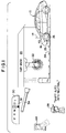
- an automotive vehicle configured as a passenger automobile 10 which has a radio therein to which an antenna 14 is connected.
- the automobile 10 has an automatic transmission 16. While an automatic transmission 16 is preferable for use in conjunction with this system, the system may also function with a standard transmission.
- the antenna 14 is telescoped to an extended position for receiving radio signals.
- the automobile 10 is shown entering a car wash 20 which includes a rotary brush 22.
- a continuous belt 24 with cogs 25 thereon engages the front wheels 26 of the automobile and drags the automobile through the car wash 20 while the brushes 22 clean the automobile.
- the automatic transmission 16 of the automobile must be in neutral.
- Either an attendant 28 or a broadcast tape instructs the driver of the automobile 10 to shift into neutral before the cogs 25 begin pulling the automobile through the car wash.
- the brushes 22 whip against the automobile's surface and in so doing may strike and snag the antenna 14.
- the antenna bends and cannot thereafter be telescoped to the retracted position. If one attempts to straighten the antenna 14, then it frequently becomes crimped.
- a crimped antenna section frequently has a diameter greater than the section into which it is to be telescoped and thus cannot be retracted by being telescoped. Numerous antennas are damaged in this fashion every year, resulting in replacement costs which cost both consumers and manufacturers a considerable amount of money.
- the present invention ameliorates this situation by automatically retracting the antenna 14 when the automatic transmission 16 is shifted from drive to neutral.
- the state of the transmission is indicated by a transmission display 30 having the transmission state indicators park “P”, reverse “R”, neutral “N”, drive “ D “, drive “D” and low “L”. Alignable with each of these letters is a pointer 32 which is moved by the shift lever 34 as the transmission 16 is shifted between various modes.
- an attendant (or tape) 28 announces the instruction "shift auto into neutral” ( Figure 1), the driver moves the lever 34 to shift the pointer 32 from the drive position " D “ to neutral “N” (see Figure 2).
- an elapsed time timer 40 located in the body computer 42 of the automobile 10, counts a 3-12 second interval. At the expiration of this time interval, the antenna 14 retracts. The timer 40 is then reset to "0" (see Figure 3), when the shift lever is moved out of the neutral position.
- the transmission display 30 has the pointer 32 in the neutral position and the antenna 14 is retracted while the automobile 10 is being washed.
- the brushes 22 cannot snag or bend the antenna 14 because the antenna is retracted within the body of the automobile 10.
- an over-ride button 44 on the instrument panel is pressed.
- the over-ride button 44 interrupts the signal from the body computer 42 which would normally retract the antenna 14.
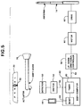
- FIG. 5 there is shown a block diagram illustrating operation of the system configured in accordance with the present invention wherein the transmission control lever 34 mounted proximate the display 30 moves the pointer 32 into alignment with the selected indicia "P", “R”, “N”, “ D “, “D” and “L” as the automotive transmission 16 ( Figures 1-4) is shifted.
- a detector 50 Aligned with the neutral position "N” is a detector 50 which senses mechanically, magnetically or perhaps optically, movement of the lever 34 to the neutral position N.
- the detector 50 causes a neutral position sensing switch 52 to close which pulses a line 54 which is connected to the timer 40 in the body computer 42.
- the body computer 42 Upon expiration of the predetermined time period, which is in the range about 3 to 15 seconds and preferably about 10 seconds, the body computer 42 instructs a controller 56 via line 58 to cause a motor 60 retract the telescoping antenna 14.
- An alternate arrangement is for the body computer 42 to have a sensor therein which detects shifting of the transmission to the neutral mode and upon detecting this shift to start the timer 40.
- Retraction of the antenna 14 is accomplished in a conventional fashion by instructing a motor 60 to rotate in a first direction to retract the antenna 14 and in a second direction to project the antenna.
- the conventional approach may include a relay (not shown) associated with the motor 60 which when released causes the motor to rotate in the first direction to retract the antenna 14.
- the over-ride button 44 is pushed which interrupts transmission of the retract signal to line 58 by disabling the timer 40 within the body computer 42. If the shift lever 34 is moved from the neutral position to any other position during the predetermined time interval, the line 54 is pulsed to reset the clock 40 by opening the switch 52, thus interrupting the signal on line 58 to the controller 56 for retracting the antenna 14. Accordingly, if the timer is reset by either moving the shift lever 34 from the neutral position or disabled by operating the over-ride button 44 prior to the expiration of the 10 second interval, the antenna 14 will not retract. If the predetermined time has elapsed and the antenna is partially or fully retracted, the antenna will immediately extend.
- the shift lever 34 is shifted from the neutral "N" position to the " D " position.
- the timer 40 is then reset and the controller 56 will cause the motor 60 to immediately raise the antenna 14. If the antenna 14 is already raised, then the signal to the controller 56 has no effect since, according to conventional practice, a signal to extend the antenna has no effect.
- step n 1 the switch 52 is closed to start the timer 40, step n 2 . If the over-ride button 44 has been pushed in step n 3 , the timer 40 is disabled in step n 4 .
- step n 5 it is determined if the transmission 16 has been shifted from neutral and, if it has, the timer 40 is reset. If the transmission has not been shifted to neutral, then in step n 6 , a signal is supplied by the computer 42 to actuate the motor 58 to retract antenna 14. If the antenna 14 has already been retracted because the radio is off, then, according to conventional practice, a redundant signal to retract does not effect the antenna 14 because, according to conventional practice a limit switch associated with the controller 56 is open.
- step n 8 the shift lever 34 is shifted from the "N" to the "D” position, causing the detector 50 to open the switch 52 which pulses the line 54 in step n 9 .
- step n 9 This causes the elapsed clock 40 to again count a 10 second interval in step n 10 .
- the timer 40 then applies a signal to line 58 which causes the controller 56 to immediately drive the motor 60 to rotate in a direction to project the antenna 14. If the antenna 14 is already projected, then the controller 56 ignores the instruction to project the antenna since, according to conventional practice, a limit switch is open in the controller applying current to rotate the motor 60 in the direction to project the antenna.
- a system 100 causes a standard power antenna circuit 101 to automatically retract the antenna 14 when the transmission 16 is shifted to neutral (see Figs. 1-5).
- a cluster connector 102 is connected to the transmission 16 to provide inputs on lines 104 and 106 from the transmission to an antenna retract control circuit 108.
- the cluster connector 102 also includes an ignition line 110, a 5 volt power line 112 and a ground line 114.
- the neutral position of the transmission 16 (when the shifter 34 is in the neutral position "N" of Figures 1-5) applies high inputs on lines 104 and 106.
- High inputs on lines 104 and 106 remove a 12 volt power feed from line 120 to the up-down directional controller 56.
- the power feed on line 120 keeps a relay 123 in the directional controller 56 energized.
- the relay Upon interrupting current to the relay 123, the relay reverses the direction of current applied to the motor 60 causing the motor to retract the antenna 14.
- ground line 124 and ignitional line 125 are also connected to the directional controller 56 which cooperate in a conventional fashion with the feed line 120 to power the motor 60.
- the antenna retract control circuit 108 is shown in detail in Figure 9 where it is seen that 12 volt power line 122 is connected to line 120 via an intermediate relay 130.
- the intermediate relay 130 includes a switch 132 which when opened removes 12 volt power from line 120 thus allowing the antenna 14 to retract.
- the intermediate relay 130 includes a coil 134 which is connected in parallel with a diode 136 through a transistor 138. When the transistor 138 is turned “on” the relay 130 opens, interrupting power to the relay 123 in the controller 56 and causing the motor 60 to retract the antenna 14.
- the transistor 138 is connected to an AND gate circuit 140 through an RC timing circuit 142.
- the AND gate circuit 140 is connected to the lines 104 and 106 which are connected to the transmission 16.
- the AND gate circuit 140 compares two electronic PRNDL bits in AND gates 144, 146 and 148. When both bits are high, the AND gate 144 starts RC timing circuit 142 which initiates a 5-second delay (the time it takes capacitor C to charge). Depending on the ratings of the capacitor and resistor, the delay may be in the range of 3 to 12 seconds with about 5 seconds being preferred.
- a signal is applied to the base of transistor 138 through an AND gate 150 which turns the transistor 138 "on” and opens intermediate relay 130 releasing the antenna 14 by opening relay 123.
- a reverse bias diode 153 is disposed in line 154 connecting AND gates 146 and 148 to AND gate 150 to block highs on lines 104 and 106 from turning on transistor 138. Whenever the bits on lines 104 and 106 are other than both high the transistor 138 will be “off.” Accordingly, when the driver shifts into reverse or drive from neutral, the RC timer 142 is immediately discharged through AND gates 146 and AND gate 148, preventing the antenna 14 from retracting.
- the AND gate 144 applies a low to a line 154 which is applied through to the transistor 138 which turns the transistor off and allows the intermediate relay 130 to close, applying power to reraise antenna 14.
- AND gates 146 and 148 continue to apply a low output on line 154 when either a low and high are applied to lines 104 and 106 or when both lines 104 and 106 are low. Consequently, the change in state of lines 104 and 106 cannot cause AND gates 146 or 148 to initiate retraction of the antenna 14.
Landscapes
- Engineering & Computer Science (AREA)
- Remote Sensing (AREA)
- Details Of Aerials (AREA)
- Fittings On The Vehicle Exterior For Carrying Loads, And Devices For Holding Or Mounting Articles (AREA)
Applications Claiming Priority (2)
| Application Number | Priority Date | Filing Date | Title |
|---|---|---|---|
| US365441 | 1994-12-28 | ||
| US08/365,441 US5525844A (en) | 1994-12-28 | 1994-12-28 | Automatically retractable radio antennas for automotive vehicles |
Publications (2)
| Publication Number | Publication Date |
|---|---|
| EP0720251A2 true EP0720251A2 (de) | 1996-07-03 |
| EP0720251A3 EP0720251A3 (de) | 1997-09-10 |
Family
ID=23438928
Family Applications (1)
| Application Number | Title | Priority Date | Filing Date |
|---|---|---|---|
| EP95120231A Withdrawn EP0720251A3 (de) | 1994-12-28 | 1995-12-20 | Automatisch versenkbare Funkantenne für Kraftfahrzeuge |
Country Status (4)
| Country | Link |
|---|---|
| US (1) | US5525844A (de) |
| EP (1) | EP0720251A3 (de) |
| JP (1) | JPH08230576A (de) |
| CA (1) | CA2165227A1 (de) |
Families Citing this family (8)
| Publication number | Priority date | Publication date | Assignee | Title |
|---|---|---|---|---|
| DE19503920C2 (de) * | 1995-02-07 | 2000-06-21 | Daimler Chrysler Ag | Einstelleinrichtung mit multifunktionalem Bedienschalter |
| AU721874B2 (en) * | 1998-07-28 | 2000-07-13 | Samsung Electronics Co., Ltd. | Method for automatically converting antenna mode in portable telephone |
| DE20113339U1 (de) | 2001-08-17 | 2002-03-07 | FUBA Automotive GmbH & Co. KG, 31162 Bad Salzdetfurth | Antennenumschaltung |
| US20060071494A1 (en) * | 2004-10-04 | 2006-04-06 | Ganz Alan S | Fender finder with extension and retraction feature |
| US7416168B1 (en) * | 2005-09-26 | 2008-08-26 | Bob's Space Racers, Inc. | Prize lift telescoping assembly |
| CN101022634B (zh) * | 2007-03-16 | 2010-07-21 | 烟台麦特电子有限公司 | 一种基于远程控制车载装置的测试方法 |
| EP2003471A1 (de) * | 2007-06-11 | 2008-12-17 | IBEO Automobile Sensor GmbH | Einziehbare Radarvorrichtung |
| US12071208B2 (en) | 2020-06-01 | 2024-08-27 | Brunswick Corporation | System and peripheral devices for a marine vessel |
Family Cites Families (10)
| Publication number | Priority date | Publication date | Assignee | Title |
|---|---|---|---|---|
| US4023887A (en) * | 1972-10-30 | 1977-05-17 | General Optimation, Inc. | Optical communication, switching and control apparatus and systems and modular electro-optical logic circuits, and applications thereof |
| DE2641071C3 (de) * | 1976-09-11 | 1981-09-03 | Daimler-Benz Ag, 7000 Stuttgart | Aus- und einfahrbare Antenne für Rundfunkempfänger |
| JPS62206902A (ja) * | 1986-03-06 | 1987-09-11 | Asmo Co Ltd | 電動アンテナ装置 |
| JPS63125451A (ja) * | 1986-11-14 | 1988-05-28 | Honda Motor Co Ltd | 車両のコ−ナポ−ル装置 |
| US4733101A (en) * | 1986-11-17 | 1988-03-22 | General Motors Corporation | Vehicle power antenna control with inhibit during cranking |
| US4803493A (en) * | 1986-12-01 | 1989-02-07 | Jamison Wayne L | Mobile antenna circuit with variable line length |
| JPH01151304A (ja) * | 1987-12-08 | 1989-06-14 | Harada Ind Co Ltd | 自動車用モータアンテナ制御装置 |
| JPH01151303A (ja) * | 1987-12-08 | 1989-06-14 | Harada Ind Co Ltd | 自動車用モータアンテナ制御装置 |
| US5235344A (en) * | 1990-03-16 | 1993-08-10 | Harada Industry Co., Ltd. | Drive control apparatus for an electrically-driven type extensible/retractable antenna |
| US5442242A (en) * | 1992-05-27 | 1995-08-15 | Yoshiko Co., Ltd. | Apparatus for driving expansion pole for use in vehicle |
-
1994
- 1994-12-28 US US08/365,441 patent/US5525844A/en not_active Expired - Lifetime
-
1995
- 1995-12-14 CA CA002165227A patent/CA2165227A1/en not_active Abandoned
- 1995-12-20 EP EP95120231A patent/EP0720251A3/de not_active Withdrawn
- 1995-12-28 JP JP7343289A patent/JPH08230576A/ja active Pending
Also Published As
| Publication number | Publication date |
|---|---|
| EP0720251A3 (de) | 1997-09-10 |
| US5525844A (en) | 1996-06-11 |
| JPH08230576A (ja) | 1996-09-10 |
| CA2165227A1 (en) | 1996-06-29 |
Similar Documents
| Publication | Publication Date | Title |
|---|---|---|
| US5525844A (en) | Automatically retractable radio antennas for automotive vehicles | |
| EP0899172B1 (de) | Regelverfahren für Scheibenwischer | |
| US4152694A (en) | Guide for aiding in backing-up vehicles | |
| EP1081002B1 (de) | Verfahren zum Verhindern eines Fahrzeugdiebstahls | |
| US5521442A (en) | Automatic power antenna retraction | |
| US20020140387A1 (en) | Method and apparatus for preparing for car wash | |
| JP2000190779A (ja) | 洗車用制御装置 | |
| JP3233391B2 (ja) | 電動コーナーポール | |
| KR20040041935A (ko) | 차량의 세차모드 전환장치 | |
| KR19990026193U (ko) | 전면거리 판단용 안전깃봉 제어 장치 | |
| JP3511945B2 (ja) | 車両用ワイパ制御装置 | |
| JP2003159941A (ja) | リアシェード制御装置 | |
| KR100509867B1 (ko) | 사이드 브레이크 자동해제 장치 및 방법 | |
| KR20030024204A (ko) | 자동차의 와이퍼 작동방법 | |
| CN119428553B (zh) | 一种电动拖车钩自清洁方法、系统、车辆及存储介质 | |
| DE102023111196B4 (de) | Anhängerkupplungsanordnung für ein Fahrzeug und Verfahren zum Betreiben einer solchen Anhängerkupplungsanordnung | |
| KR890003993Y1 (ko) | 자동차의 후미관찰용 백미러 | |
| US3440605A (en) | Retractable curb feeler | |
| KR960013248B1 (ko) | 자동차후방감시경의 작동장치 | |
| WO1998050245A1 (en) | Gear lock | |
| KR100187432B1 (ko) | 자동차의 접촉사고 방지장치 | |
| JPH04337902A (ja) | 自動車用アンテナ装置 | |
| JP3256837B2 (ja) | 車輌用エンジンの遠隔始動方法およびその装置 | |
| JP2025144071A (ja) | 開閉装置制御システム及びリモコン | |
| JP3307296B2 (ja) | 車両の格納ミラー制御装置 |
Legal Events
| Date | Code | Title | Description |
|---|---|---|---|
| PUAI | Public reference made under article 153(3) epc to a published international application that has entered the european phase |
Free format text: ORIGINAL CODE: 0009012 |
|
| AK | Designated contracting states |
Kind code of ref document: A2 Designated state(s): AT DE FR GB |
|
| PUAL | Search report despatched |
Free format text: ORIGINAL CODE: 0009013 |
|
| AK | Designated contracting states |
Kind code of ref document: A3 Designated state(s): AT DE FR GB |
|
| STAA | Information on the status of an ep patent application or granted ep patent |
Free format text: STATUS: THE APPLICATION IS DEEMED TO BE WITHDRAWN |
|
| 18D | Application deemed to be withdrawn |
Effective date: 19970310 |