EP0720258B1 - Connecteur à déplacement d'isolant - Google Patents
Connecteur à déplacement d'isolant Download PDFInfo
- Publication number
- EP0720258B1 EP0720258B1 EP95306395A EP95306395A EP0720258B1 EP 0720258 B1 EP0720258 B1 EP 0720258B1 EP 95306395 A EP95306395 A EP 95306395A EP 95306395 A EP95306395 A EP 95306395A EP 0720258 B1 EP0720258 B1 EP 0720258B1
- Authority
- EP
- European Patent Office
- Prior art keywords
- insulation displacement
- gaps
- gap
- cable
- sheathed
- Prior art date
- Legal status (The legal status is an assumption and is not a legal conclusion. Google has not performed a legal analysis and makes no representation as to the accuracy of the status listed.)
- Expired - Lifetime
Links
- 238000009413 insulation Methods 0.000 title claims description 44
- 238000006073 displacement reaction Methods 0.000 title claims description 36
- 230000037431 insertion Effects 0.000 claims description 33
- 238000003780 insertion Methods 0.000 claims description 33
- 239000004020 conductor Substances 0.000 claims description 4
- 238000004519 manufacturing process Methods 0.000 description 2
- 230000002708 enhancing effect Effects 0.000 description 1
- 239000000463 material Substances 0.000 description 1
- 239000000088 plastic resin Substances 0.000 description 1
Images




Classifications
-
- H—ELECTRICITY
- H01—ELECTRIC ELEMENTS
- H01R—ELECTRICALLY-CONDUCTIVE CONNECTIONS; STRUCTURAL ASSOCIATIONS OF A PLURALITY OF MUTUALLY-INSULATED ELECTRICAL CONNECTING ELEMENTS; COUPLING DEVICES; CURRENT COLLECTORS
- H01R13/00—Details of coupling devices of the kinds covered by groups H01R12/70 or H01R24/00 - H01R33/00
- H01R13/58—Means for relieving strain on wire connection, e.g. cord grip, for avoiding loosening of connections between wires and terminals within a coupling device terminating a cable
- H01R13/5833—Means for relieving strain on wire connection, e.g. cord grip, for avoiding loosening of connections between wires and terminals within a coupling device terminating a cable the cable being forced in a tortuous or curved path, e.g. knots in cable
-
- H—ELECTRICITY
- H01—ELECTRIC ELEMENTS
- H01R—ELECTRICALLY-CONDUCTIVE CONNECTIONS; STRUCTURAL ASSOCIATIONS OF A PLURALITY OF MUTUALLY-INSULATED ELECTRICAL CONNECTING ELEMENTS; COUPLING DEVICES; CURRENT COLLECTORS
- H01R4/00—Electrically-conductive connections between two or more conductive members in direct contact, i.e. touching one another; Means for effecting or maintaining such contact; Electrically-conductive connections having two or more spaced connecting locations for conductors and using contact members penetrating insulation
- H01R4/24—Connections using contact members penetrating or cutting insulation or cable strands
- H01R4/2416—Connections using contact members penetrating or cutting insulation or cable strands the contact members having insulation-cutting edges, e.g. of tuning fork type
- H01R4/242—Connections using contact members penetrating or cutting insulation or cable strands the contact members having insulation-cutting edges, e.g. of tuning fork type the contact members being plates having a single slot
- H01R4/2425—Flat plates, e.g. multi-layered flat plates
- H01R4/2429—Flat plates, e.g. multi-layered flat plates mounted in an insulating base
Definitions
- This invention relates to an insulation displacement connector in which a guide structure for a sheathed cable is improved.
- FIG. 12 is a perspective view of the conventional insulation displacement connector.
- a conventional insulation displacement connector comprises a connector housing 1, a plurality of guide projections 2 which stand on the connector housing 1 at a given distance to define cable insertion gaps 3, and an insulation displacement terminal 4 mounted on the connector housing 1.
- the cables 5 are subject to a substantial pressing resistance.
- a press machine is used upon a cable insertion work. In this case, all cables 5 are temporarily inserted in the cable insertion gaps and then the temporary assembly is set on the press machine to carry out the cable insertion work.
- the sheathed cables 5 inserted in the gaps 3 are readily moved longitudinally by an external force since a structure in which the sheathed cables 5 are temporarily inserted in the cable insertion gaps 3 cannot generate a sufficient force to hold the cables 5.
- a short sheathed cable 5 is moved in the gaps 3
- the cable 5 comes out of the connector housing 1.
- a connecting portion of the cable is displaced from a predetermined position. This results in the troublesome task of correcting the displacement of the cable upon the cable insertion work.
- a connector according to the preamble of claim 1 is disclosed in DE-A-3602812 in which a cable is received in a V-shaped gap having serrations on opposed sides of the gap to grip the cable and prevent the cable coming out of the gap.
- An object of the present invention is to provide an insulation displacement connector which can effectively prevent a sheathed cable from being moved after being temporarily inserted into cable insertion gaps.
- an insulation displacement connector having a plurality of cable insertion gaps defined between guide projections spaced apart a given distance on a connector housing, at least one of the two guide projections defining each gap being provided with a holding ridge providing a holding ridge on at least one side of the gap adapted to compress an insulation sheath of a sheathed cable inserted into the gap, and the connector housing being provided with an insulation displacement terminal adapted to grip the insulation sheaths of sheathed cables inserted into the gaps so that the terminal makes contact with core conductors in the sheathed cables characterised in that each holding ridge extends in the direction of insertion of the sheathed cables into the gaps whereby the cables are by the holding ridges prevented from moving in a longitudinal direction.
- the holding ridges on the guide projections grip the insulation sheath of the sheathed cable temporarily inserted in the cable insertion gaps to hold the cable in the gaps. It is also possible to enhance the holding force of the cable.
- the guide projections defining each gap may be provided on each of the opposite sides of the gap with a shoulder extending inwardly at an upper end of the gap to prevent the sheathed cable from coming out of the gaps.
- Each of the guide projections may be provided with a vertical slit extending from an upper free end thereof to a proximal end for permitting the projection to be elastically deformed.
- a sheathed cable is inserted into the cable insertion gap between the guide projections and then pressed into the insulation displacement terminal to grip the insulation sheath of the sheathed cable.
- Holding ridges may be provided on one or both of the opposite sides defining the gaps and compress the insulation sheaths of the sheathed cables inserted in the cable insertion gaps.
- the sheathed cable is constrained from moving in a vertical direction by the shoulders as well as in a longitudinal direction by the holding ridges.
- the slit formed longitudinally in the guide projection permits the cable insertion gap to spread elastically upon insertion of the sheathed cable, thereby causing the holding ridge to grip the insulation sheath more strongly.
- FIG. 1 is an exploded perspective view of an embodiment of an insulation displacement connector of the present invention
- FIG. 2 is an enlarged perspective view of guide projections of the insulation displacement connector shown in FIG. 1;
- FIG. 3 is a cross sectional view of the guide projections of the insulation displacement connector shown in FIG. 1;
- FIG. 4 is a similar view to FIG. 3, but illustrating sheathed cables inserted in insertion gaps between the guide projections of the insulation displacement connector;
- FIG. 5 is a cross sectional view of guide projections in another embodiment of the present invention.
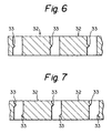
- FIG. 6 is a cross sectional view of guide projections in still another embodiment of the present invention.
- FIG. 7 is a cross sectional view of guide projections in still another embodiment of the present invention.
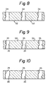
- FIG. 8 is a cross sectional view of guide projections in still another embodiment of the present invention.
- FIG. 9 is a cross sectional view of guide projections in still another embodiment of the present invention.
- FIG. 10 is a cross sectional view of guide projections in still another embodiment of the present invention.
- FIG. 11 is a cross sectional view of guide projections in still another embodiment of the present invention.
- FIG. 12 is a perspective view of a conventional insulation displacement connector.
- FIG. 1 shows a general structure of an insulation displacement connector of the present invention.
- a connector housing 11 made of a plastic resin material is provided on a base 12 with a number of guide projections 13 in two rows.
- Each guide projection 13 is disposed on the base 12 by a distance corresponding to an outer diameter of a sheathed cable 14 to define a cable insertion gap 15 between the adjacent guide projections 13 for receiving the sheathed cable 14.
- Terminal holding projections 16 are disposed on the base 12 between the rows of the guide projections 13.
- An insulation displacement terminal 17 is mounted on the terminal holding projections 16.
- the terminal 17 has connection gaps 18 corresponding to the respective cable insertion gaps in the connector housing 11. When the sheathed cable 14 is pressed in the connector gaps 18, the insulation displacement terminal 17 breaks an insulation sheath 14a (FIG. 2) of the sheathed cable 14 to make electrical contact with core conductors 14b.
- a cover 19 is formed into a box-like body which is open at the bottom.
- the cover 19 is provided on its upper interior with a plurality of press ridges (not shown) corresponding to the respective connection gaps 18 in the terminal 17.
- the guide projection 13 is provided on each of the opposite sides of the top end (the upper end in FIG. 2) with a shoulder 22 extending toward the insertion gap 15 so that the guide projection 15 is formed into a T-shape.
- the shoulder 22 is provided on each of its upper portions with a slant face 22a extending down to the cable insertion gap 15.
- the distance between the shoulders 22 is set to be slightly narrower than an outer diameter of the sheathed cable 14.
- the guide projection 13 is provided on each of its opposite sides facing the cable insertion gaps 15 with a holding ridge 21 which extends from the underside of the shoulder 22 to the proximal end and has a triangular shape in cross section.
- a single sheathed cable 14 is inserted into the cable insertion gaps 15 in the connector housing 11.
- the sheathed cable 14 makes contact with the slant faces 22a on the shoulders 22, the distance between the adjacent guide projections is elastically increased, thereby permitting the sheathed cable 14 to enter the cable insertion gaps 15.
- the holding ridges 21 gently grip the insulation sheath 14a of the sheathed cable 14, as shown in FIG. 4, so that the sheathed cable 14 is prevented from moving longitudinally. Then, the next sheathed cable 14 is inserted into another cable insertion gap 15.
- the cover 19 is mounted on the connector, the connector with the cover 19 is set on the press machine not shown, and the cover 19 is pushed down by the press machine. Then, the press ridges on the cover 19 push down each sheathed cable 14 in the gaps 15, thereby pressing the sheathed cables 14 into the connector gaps 18 in the insulation displacement terminal 17. Thus, insertion of the respective cables is finished.
- the present embodiment it is possible to surely prevent the sheathed cables 14 from moving longitudinally even if a worker touches the sheathed cable 14 inserted in the gaps 15 when the next cable 14 is inserted into the gaps 15 after one cable 14 has been inserted in the gaps 15, since the holding ridges 21 grip the sheathed cables 14 to prevent the cables 14 from moving longitudinally when the sheathed cables 14 is inserted into the gaps 15. Accordingly, it is possible to carry out the task of inserting the next sheathed cable 14 without worrying about any movement of the cables 14 which have already been inserted in the gaps 15; it is also possible to carry out the job efficiently, to eliminate having to correct the displaced cables, and eventually to improve production efficiency. Further, since each guide projection 13 is provided on its top end with the shoulders 22, it is possible to prevent the sheathed cables 14 from coming out of the gaps 15 even if the inserted cables 14 are pulled upwardly during insertion of the next cable 14.
Landscapes
- Details Of Connecting Devices For Male And Female Coupling (AREA)
- Connections By Means Of Piercing Elements, Nuts, Or Screws (AREA)
- Connections Effected By Soldering, Adhesion, Or Permanent Deformation (AREA)
Claims (10)
- Connecteur à déplacement d'isolant comportant une pluralité d'espaces d'insertion de câble (15) définis entre des saillies de guidage (13 ; 30 ; 32) espacées d'une distance donnée sur un boítier de connecteur (11), au moins l'une des deux saillies de guidage (13 ; 30 ; 32) définissant chaque espace (15) étant pourvue d'une arête de maintien (21 ; 31 ; 33 ; 34 ; 35) réalisant une arête de maintien (21 ; 31 ; 33 ; 34 ; 35) sur au moins un côté de l'espace (15) adaptée pour comprimer une gaine isolante (14a) d'un câble gainé (14) inséré dans l'espace (15), et le boítier de connecteur (11) étant pourvu d'une borne de déplacement d'isolant (17) adaptée pour serrer les gaines isolantes (14a) des câbles gainés (14) insérés dans les espaces (15), de sorte que la borne (17) entre en contact avec l'âme conductrice (14b) dans les câbles gainés (14), caractérisé en ce que chaque arête de maintien (21 ; 31 ; 33 ; 34 ; 35) s'étend dans la direction d'insertion des câbles gainés (14) dans les espaces (15), de telle manière que le déplacement dans une direction longitudinale des câbles (14) soit empêché par les arêtes de maintien (21 ; 31 ; 33 ; 34 ; 35).
- Connecteur à déplacement d'isolant selon la revendication 1, caractérisé en ce que les saillies de guidage (13) définissant chaque espace (15) sont pourvues d'épaulements (22) opposés orientés vers l'intérieur à une extrémité supérieure de l'espace (15) pour empêcher les câbles gainés (14) de sortir des espaces (15), et chaque épaulement (22) comporte, de préférence, une face inclinée (22a) sur sa partie supérieure s'étendant vers l'espace (15).
- Connecteur à déplacement d'isolant selon la revendication 1 ou la revendication 2, caractérisé en ce que chaque saillie de guidage (13) est pourvue d'une fente verticale (36) s'étendant depuis une extrémité libre supérieure jusqu'à une extrémité proximale pour permettre la déformation élastique de ladite saillie de guidage.
- Connecteur à déplacement d'isolant selon l'une quelconque des revendications précédentes, caractérisé en ce que chaque arête de maintien (21 ; 33) a une section de forme triangulaire.
- Connecteur à déplacement d'isolant selon l'une quelconque des revendications 1 à 3, caractérisé en ce que chaque arête de maintien (34 ; 35) a une section de forme semi-circulaire.
- Connecteur à déplacement d'isolant selon l'une quelconque des revendications précédentes, caractérisé en ce que chaque espace (15) comporte une arête de maintien (33 ; 35) sur un côté seulement.
- Connecteur à déplacement d'isolant selon l'une quelconque des revendications 1 à 5, caractérisé en ce que chaque espace (15) comporte une arête de maintien (21 ; 31; 33 ; 34 ; 35) sur chaque côté (15).
- Connecteur à déplacement d'isolant selon la revendication 7, caractérisé en ce que des arêtes de maintien (21 ; 35) sont alignées les unes en face des autres.
- Connecteur à déplacement d'isolant selon la revendication 7, caractérisé en ce que les arêtes de maintien (31 ; 33 ; 35) sont décalées les unes par rapport aux autres.
- Connecteur à déplacement d'isolant selon l'une quelconque des revendications précédentes, caractérisé en ce que la borne de déplacement d'isolant (17) comporte une pluralité d'espaces de connecteur (18) correspondant aux espaces d'insertion (15) et les câbles gainés (14) sont pressés dans les espaces de connecteur (18) lorsqu'un capot (19) est monté sur le boítier de connecteur (11).
Applications Claiming Priority (3)
| Application Number | Priority Date | Filing Date | Title |
|---|---|---|---|
| JP33807194 | 1994-12-26 | ||
| JP6338071A JPH08180909A (ja) | 1994-12-26 | 1994-12-26 | 圧接コネクタ |
| JP338071/94 | 1994-12-26 |
Publications (3)
| Publication Number | Publication Date |
|---|---|
| EP0720258A2 EP0720258A2 (fr) | 1996-07-03 |
| EP0720258A3 EP0720258A3 (fr) | 1997-05-28 |
| EP0720258B1 true EP0720258B1 (fr) | 2001-11-07 |
Family
ID=18314639
Family Applications (1)
| Application Number | Title | Priority Date | Filing Date |
|---|---|---|---|
| EP95306395A Expired - Lifetime EP0720258B1 (fr) | 1994-12-26 | 1995-09-13 | Connecteur à déplacement d'isolant |
Country Status (4)
| Country | Link |
|---|---|
| US (1) | US5681181A (fr) |
| EP (1) | EP0720258B1 (fr) |
| JP (1) | JPH08180909A (fr) |
| DE (1) | DE69523729T2 (fr) |
Families Citing this family (11)
| Publication number | Priority date | Publication date | Assignee | Title |
|---|---|---|---|---|
| GB9616098D0 (en) * | 1996-07-31 | 1996-09-11 | Amp Great Britain | Wire retainer |
| CH692435A5 (de) * | 1997-05-27 | 2002-06-14 | Fridolin Alois Frech | Anschlusselement für HF-Kabel. |
| NL1010168C2 (nl) * | 1998-09-23 | 2000-03-31 | Zweva Engineering B V | Verbindingsinrichting voor buizen, kabels en dergelijke. |
| KR100326803B1 (ko) * | 1999-06-30 | 2002-03-04 | 이계철 | 터미널 블럭 |
| FR2810165B1 (fr) * | 2000-06-09 | 2006-10-06 | Entrelec Sa | Dispositif de connexion autodenudante pour un conducteur electrique gaine |
| US6406326B2 (en) * | 2000-06-26 | 2002-06-18 | Yazaki Corporation | Wire holding structure |
| US7530827B2 (en) * | 2007-05-22 | 2009-05-12 | Penduit Corp. | Raceway IDC connector |
| JP5600461B2 (ja) * | 2010-03-31 | 2014-10-01 | 日本クロージャー株式会社 | 合成樹脂製容器蓋 |
| JP6247017B2 (ja) * | 2013-04-16 | 2017-12-13 | 日本圧着端子製造株式会社 | 圧接コネクタ及びこれに用いられるハウジング |
| JP6614051B2 (ja) * | 2016-07-12 | 2019-12-04 | 株式会社オートネットワーク技術研究所 | 電気接続アセンブリの製造方法 |
| JP7311309B2 (ja) * | 2019-05-13 | 2023-07-19 | 矢崎総業株式会社 | コネクタ |
Family Cites Families (8)
| Publication number | Priority date | Publication date | Assignee | Title |
|---|---|---|---|---|
| US3848954A (en) * | 1973-06-06 | 1974-11-19 | Reliable Electric Co | Clip terminal and applicator tool combination |
| JPS5514652A (en) * | 1978-07-19 | 1980-02-01 | Yamaichi Electric Mfg | Electric terminal |
| US4552429A (en) * | 1984-10-01 | 1985-11-12 | Amp Incorporated | Modular electrical connector for connecting wires in cable ends |
| DE3641367C1 (en) * | 1986-12-03 | 1988-02-25 | Krone Ag | Device for connecting drop-wire cable cores |
| DE3602812C2 (de) * | 1986-01-30 | 1994-06-30 | Fraunhofer Ges Forschung | Elektrischer Verbinder |
| US4693536A (en) * | 1986-06-12 | 1987-09-15 | Molex Incorporated | Insulation displacement terminal |
| JPH0740300Y2 (ja) * | 1989-05-19 | 1995-09-13 | 日本エー・エム・ピー株式会社 | 圧接コネクタ |
| JPH03121664A (ja) * | 1989-10-05 | 1991-05-23 | Canon Inc | 通信装置 |
-
1994
- 1994-12-26 JP JP6338071A patent/JPH08180909A/ja active Pending
-
1995
- 1995-09-12 US US08/527,258 patent/US5681181A/en not_active Expired - Lifetime
- 1995-09-13 EP EP95306395A patent/EP0720258B1/fr not_active Expired - Lifetime
- 1995-09-13 DE DE69523729T patent/DE69523729T2/de not_active Expired - Fee Related
Also Published As
| Publication number | Publication date |
|---|---|
| EP0720258A2 (fr) | 1996-07-03 |
| US5681181A (en) | 1997-10-28 |
| DE69523729D1 (de) | 2001-12-13 |
| EP0720258A3 (fr) | 1997-05-28 |
| DE69523729T2 (de) | 2002-08-01 |
| JPH08180909A (ja) | 1996-07-12 |
Similar Documents
| Publication | Publication Date | Title |
|---|---|---|
| CA2043207C (fr) | Contact serre-fil a pointe | |
| US4084876A (en) | Electrical connector | |
| US5030136A (en) | Connector for cables | |
| US6406323B2 (en) | Multi wire insulation displacement contact and a method of making multi wire terminations | |
| US3998514A (en) | Device armed with a terminal for making electrical connection with a conductor | |
| EP0720258B1 (fr) | Connecteur à déplacement d'isolant | |
| US5194014A (en) | Cable connector and contact terminal therefor | |
| EP0251736B1 (fr) | Dispositif de fixation de fils dans un connecteur électrique | |
| US5897394A (en) | Conductor connection terminal and method of connection | |
| EP0232591B1 (fr) | Connecteur électrique pour plusieurs circuits | |
| EP0650218B1 (fr) | Connecteur de serrage | |
| US5500999A (en) | Terminal crimping device | |
| KR19990014851A (ko) | 전선 접속용 시스템 | |
| US5659948A (en) | Termination tool for modular telephone connector | |
| GB2197758A (en) | Insulation displacement connector | |
| EP0057780A1 (fr) | Connecteur électrique comprenant une borne ayant une partie fendue de réception du fil et des moyens pour atténuer l'effort de tension sur le fil | |
| EP0234639B1 (fr) | Connecteur à déplacement d'isolant | |
| JPS60221977A (ja) | ケ−ブル終端用コネクタ | |
| US6413116B2 (en) | Insulation-displacement connection piece | |
| EP0152690B1 (fr) | Assemblage pour connecteur multi-conducteur à déplacement d'isolant | |
| US3980379A (en) | Electrical connector | |
| US20060030199A1 (en) | Multi wire insulation displacement contact and a method of making multi wire terminations | |
| EP0251755A2 (fr) | Connecteur électrique compact | |
| AU2005203509A1 (en) | Multi wire insulation displacement contact and a method of making multi wire terminations | |
| GB2261777A (en) | Pole holding member for an electrical connector |
Legal Events
| Date | Code | Title | Description |
|---|---|---|---|
| PUAI | Public reference made under article 153(3) epc to a published international application that has entered the european phase |
Free format text: ORIGINAL CODE: 0009012 |
|
| 17P | Request for examination filed |
Effective date: 19951006 |
|
| AK | Designated contracting states |
Kind code of ref document: A2 Designated state(s): DE FR GB |
|
| PUAL | Search report despatched |
Free format text: ORIGINAL CODE: 0009013 |
|
| AK | Designated contracting states |
Kind code of ref document: A3 Designated state(s): DE FR GB |
|
| 17Q | First examination report despatched |
Effective date: 19991028 |
|
| GRAG | Despatch of communication of intention to grant |
Free format text: ORIGINAL CODE: EPIDOS AGRA |
|
| GRAG | Despatch of communication of intention to grant |
Free format text: ORIGINAL CODE: EPIDOS AGRA |
|
| GRAH | Despatch of communication of intention to grant a patent |
Free format text: ORIGINAL CODE: EPIDOS IGRA |
|
| GRAH | Despatch of communication of intention to grant a patent |
Free format text: ORIGINAL CODE: EPIDOS IGRA |
|
| GRAA | (expected) grant |
Free format text: ORIGINAL CODE: 0009210 |
|
| AK | Designated contracting states |
Kind code of ref document: B1 Designated state(s): DE FR GB |
|
| REF | Corresponds to: |
Ref document number: 69523729 Country of ref document: DE Date of ref document: 20011213 |
|
| REG | Reference to a national code |
Ref country code: GB Ref legal event code: IF02 |
|
| PG25 | Lapsed in a contracting state [announced via postgrant information from national office to epo] |
Ref country code: GB Free format text: LAPSE BECAUSE OF NON-PAYMENT OF DUE FEES Effective date: 20020913 |
|
| PLBE | No opposition filed within time limit |
Free format text: ORIGINAL CODE: 0009261 |
|
| STAA | Information on the status of an ep patent application or granted ep patent |
Free format text: STATUS: NO OPPOSITION FILED WITHIN TIME LIMIT |
|
| 26N | No opposition filed | ||
| PG25 | Lapsed in a contracting state [announced via postgrant information from national office to epo] |
Ref country code: DE Free format text: LAPSE BECAUSE OF NON-PAYMENT OF DUE FEES Effective date: 20030401 |
|
| GBPC | Gb: european patent ceased through non-payment of renewal fee |
Effective date: 20020913 |
|
| PG25 | Lapsed in a contracting state [announced via postgrant information from national office to epo] |
Ref country code: FR Free format text: LAPSE BECAUSE OF NON-PAYMENT OF DUE FEES Effective date: 20030603 |
|
| REG | Reference to a national code |
Ref country code: FR Ref legal event code: ST |