EP0720883B2 - Méthode et dispositif à travailler des pièces à surfaces excentriques principalement à surface de rotation - Google Patents
Méthode et dispositif à travailler des pièces à surfaces excentriques principalement à surface de rotation Download PDFInfo
- Publication number
- EP0720883B2 EP0720883B2 EP95120291A EP95120291A EP0720883B2 EP 0720883 B2 EP0720883 B2 EP 0720883B2 EP 95120291 A EP95120291 A EP 95120291A EP 95120291 A EP95120291 A EP 95120291A EP 0720883 B2 EP0720883 B2 EP 0720883B2
- Authority
- EP
- European Patent Office
- Prior art keywords
- workpiece
- axis
- milling cutter
- milling
- rotational
- Prior art date
- Legal status (The legal status is an assumption and is not a legal conclusion. Google has not performed a legal analysis and makes no representation as to the accuracy of the status listed.)
- Expired - Lifetime
Links
- 238000000034 method Methods 0.000 title claims abstract description 16
- 238000003801 milling Methods 0.000 claims abstract description 72
- 238000003754 machining Methods 0.000 claims abstract description 23
- 238000005520 cutting process Methods 0.000 claims description 26
- 238000005065 mining Methods 0.000 claims 5
- 238000006073 displacement reaction Methods 0.000 claims 2
- 238000012545 processing Methods 0.000 description 17
- 238000004519 manufacturing process Methods 0.000 description 3
- 238000003672 processing method Methods 0.000 description 2
- 241000985128 Cladium mariscus Species 0.000 description 1
- 238000009412 basement excavation Methods 0.000 description 1
- 238000010923 batch production Methods 0.000 description 1
- 230000015572 biosynthetic process Effects 0.000 description 1
- 230000002349 favourable effect Effects 0.000 description 1
- 210000001061 forehead Anatomy 0.000 description 1
- 238000000227 grinding Methods 0.000 description 1
- 238000012805 post-processing Methods 0.000 description 1
- 230000000750 progressive effect Effects 0.000 description 1
- 230000001360 synchronised effect Effects 0.000 description 1
Images


Classifications
-
- B—PERFORMING OPERATIONS; TRANSPORTING
- B23—MACHINE TOOLS; METAL-WORKING NOT OTHERWISE PROVIDED FOR
- B23D—PLANING; SLOTTING; SHEARING; BROACHING; SAWING; FILING; SCRAPING; LIKE OPERATIONS FOR WORKING METAL BY REMOVING MATERIAL, NOT OTHERWISE PROVIDED FOR
- B23D37/00—Broaching machines or broaching devices
- B23D37/005—Broaching machines or broaching devices for cylindrical workpieces, e.g. crankshafts
-
- B—PERFORMING OPERATIONS; TRANSPORTING
- B23—MACHINE TOOLS; METAL-WORKING NOT OTHERWISE PROVIDED FOR
- B23C—MILLING
- B23C3/00—Milling particular work; Special milling operations; Machines therefor
- B23C3/06—Milling crankshafts
-
- B—PERFORMING OPERATIONS; TRANSPORTING
- B23—MACHINE TOOLS; METAL-WORKING NOT OTHERWISE PROVIDED FOR
- B23C—MILLING
- B23C2220/00—Details of milling processes
- B23C2220/08—Milling with the axis of the tool perpendicular to the workpiece axis
-
- B—PERFORMING OPERATIONS; TRANSPORTING
- B23—MACHINE TOOLS; METAL-WORKING NOT OTHERWISE PROVIDED FOR
- B23C—MILLING
- B23C2220/00—Details of milling processes
- B23C2220/64—Using an endmill, i.e. a shaft milling cutter, to generate profile of a crankshaft or camshaft
-
- B—PERFORMING OPERATIONS; TRANSPORTING
- B23—MACHINE TOOLS; METAL-WORKING NOT OTHERWISE PROVIDED FOR
- B23D—PLANING; SLOTTING; SHEARING; BROACHING; SAWING; FILING; SCRAPING; LIKE OPERATIONS FOR WORKING METAL BY REMOVING MATERIAL, NOT OTHERWISE PROVIDED FOR
- B23D43/00—Broaching tools
- B23D43/06—Broaching tools for cutting by rotational movement
- B23D2043/063—Broaching tools for cutting by rotational movement with cutters mounted externally
-
- Y—GENERAL TAGGING OF NEW TECHNOLOGICAL DEVELOPMENTS; GENERAL TAGGING OF CROSS-SECTIONAL TECHNOLOGIES SPANNING OVER SEVERAL SECTIONS OF THE IPC; TECHNICAL SUBJECTS COVERED BY FORMER USPC CROSS-REFERENCE ART COLLECTIONS [XRACs] AND DIGESTS
- Y10—TECHNICAL SUBJECTS COVERED BY FORMER USPC
- Y10T—TECHNICAL SUBJECTS COVERED BY FORMER US CLASSIFICATION
- Y10T29/00—Metal working
- Y10T29/17—Crankshaft making apparatus
-
- Y—GENERAL TAGGING OF NEW TECHNOLOGICAL DEVELOPMENTS; GENERAL TAGGING OF CROSS-SECTIONAL TECHNOLOGIES SPANNING OVER SEVERAL SECTIONS OF THE IPC; TECHNICAL SUBJECTS COVERED BY FORMER USPC CROSS-REFERENCE ART COLLECTIONS [XRACs] AND DIGESTS
- Y10—TECHNICAL SUBJECTS COVERED BY FORMER USPC
- Y10T—TECHNICAL SUBJECTS COVERED BY FORMER US CLASSIFICATION
- Y10T29/00—Metal working
- Y10T29/49—Method of mechanical manufacture
- Y10T29/49229—Prime mover or fluid pump making
- Y10T29/49286—Crankshaft making
-
- Y—GENERAL TAGGING OF NEW TECHNOLOGICAL DEVELOPMENTS; GENERAL TAGGING OF CROSS-SECTIONAL TECHNOLOGIES SPANNING OVER SEVERAL SECTIONS OF THE IPC; TECHNICAL SUBJECTS COVERED BY FORMER USPC CROSS-REFERENCE ART COLLECTIONS [XRACs] AND DIGESTS
- Y10—TECHNICAL SUBJECTS COVERED BY FORMER USPC
- Y10T—TECHNICAL SUBJECTS COVERED BY FORMER US CLASSIFICATION
- Y10T29/00—Metal working
- Y10T29/51—Plural diverse manufacturing apparatus including means for metal shaping or assembling
- Y10T29/5104—Type of machine
- Y10T29/5109—Lathe
-
- Y—GENERAL TAGGING OF NEW TECHNOLOGICAL DEVELOPMENTS; GENERAL TAGGING OF CROSS-SECTIONAL TECHNOLOGIES SPANNING OVER SEVERAL SECTIONS OF THE IPC; TECHNICAL SUBJECTS COVERED BY FORMER USPC CROSS-REFERENCE ART COLLECTIONS [XRACs] AND DIGESTS
- Y10—TECHNICAL SUBJECTS COVERED BY FORMER USPC
- Y10T—TECHNICAL SUBJECTS COVERED BY FORMER US CLASSIFICATION
- Y10T409/00—Gear cutting, milling, or planing
- Y10T409/30—Milling
- Y10T409/304536—Milling including means to infeed work to cutter
- Y10T409/305544—Milling including means to infeed work to cutter with work holder
- Y10T409/305656—Milling including means to infeed work to cutter with work holder including means to support work for rotation during operation
- Y10T409/305712—Milling including means to infeed work to cutter with work holder including means to support work for rotation during operation and including means to infeed cutter toward work axis
-
- Y—GENERAL TAGGING OF NEW TECHNOLOGICAL DEVELOPMENTS; GENERAL TAGGING OF CROSS-SECTIONAL TECHNOLOGIES SPANNING OVER SEVERAL SECTIONS OF THE IPC; TECHNICAL SUBJECTS COVERED BY FORMER USPC CROSS-REFERENCE ART COLLECTIONS [XRACs] AND DIGESTS
- Y10—TECHNICAL SUBJECTS COVERED BY FORMER USPC
- Y10T—TECHNICAL SUBJECTS COVERED BY FORMER US CLASSIFICATION
- Y10T409/00—Gear cutting, milling, or planing
- Y10T409/30—Milling
- Y10T409/306664—Milling including means to infeed rotary cutter toward work
- Y10T409/30756—Machining arcuate surface
-
- Y—GENERAL TAGGING OF NEW TECHNOLOGICAL DEVELOPMENTS; GENERAL TAGGING OF CROSS-SECTIONAL TECHNOLOGIES SPANNING OVER SEVERAL SECTIONS OF THE IPC; TECHNICAL SUBJECTS COVERED BY FORMER USPC CROSS-REFERENCE ART COLLECTIONS [XRACs] AND DIGESTS
- Y10—TECHNICAL SUBJECTS COVERED BY FORMER USPC
- Y10T—TECHNICAL SUBJECTS COVERED BY FORMER US CLASSIFICATION
- Y10T409/00—Gear cutting, milling, or planing
- Y10T409/30—Milling
- Y10T409/306664—Milling including means to infeed rotary cutter toward work
- Y10T409/307672—Angularly adjustable cutter head
-
- Y—GENERAL TAGGING OF NEW TECHNOLOGICAL DEVELOPMENTS; GENERAL TAGGING OF CROSS-SECTIONAL TECHNOLOGIES SPANNING OVER SEVERAL SECTIONS OF THE IPC; TECHNICAL SUBJECTS COVERED BY FORMER USPC CROSS-REFERENCE ART COLLECTIONS [XRACs] AND DIGESTS
- Y10—TECHNICAL SUBJECTS COVERED BY FORMER USPC
- Y10T—TECHNICAL SUBJECTS COVERED BY FORMER US CLASSIFICATION
- Y10T409/00—Gear cutting, milling, or planing
- Y10T409/40—Broaching
- Y10T409/400175—Process
-
- Y—GENERAL TAGGING OF NEW TECHNOLOGICAL DEVELOPMENTS; GENERAL TAGGING OF CROSS-SECTIONAL TECHNOLOGIES SPANNING OVER SEVERAL SECTIONS OF THE IPC; TECHNICAL SUBJECTS COVERED BY FORMER USPC CROSS-REFERENCE ART COLLECTIONS [XRACs] AND DIGESTS
- Y10—TECHNICAL SUBJECTS COVERED BY FORMER USPC
- Y10T—TECHNICAL SUBJECTS COVERED BY FORMER US CLASSIFICATION
- Y10T82/00—Turning
- Y10T82/19—Lathe for crank or crank pin
Definitions
- the invention relates to a method for processing of workpieces as in the preamble of claim 1 and a machine according to the The preamble of claim 9 and as e.g. from AT-B-286067 is known.
- crankshaft is a very typical one Workpiece is, this workpiece is in the following Description used throughout exemplarily, without the application of the invention thereto should be limited.
- the invention also for non-rotationally symmetric surfaces, such as the cams of a camshaft, also applicable.
- crankshaft machining is the processing the centrally located main bearings of to distinguish the eccentric Hublagerstellen.
- crankshaft As a processing method for the production the crankshaft is in addition to conventional turning, the so-called whirling (milling with the crankshaft comprehensive, internally toothed annular Milling), above all, the twisting (a curved Broaching tool pivots parallel next to the rotating one Crankshaft) and the rotary lathe (the Swiveling lathe tool is without simultaneous Pivoting movement in the pure puncture procedure such as a turning tool for specific work steps used, alternating with turn-broaching) known.
- whirling milling with the crankshaft comprehensive, internally toothed annular Milling
- twisting a curved Broaching tool pivots parallel next to the rotating one Crankshaft
- rotary lathe the Swiveling lathe tool is without simultaneous Pivoting movement in the pure puncture procedure such as a turning tool for specific work steps used, alternating with turn-broaching
- EP-A-0 417 446 can be pin bearing pin as well as the main bearing pins worked be when the crankshaft for this purpose is eccentrically clamped, so that the spindle axis the driving tool spindles (in the Usually the crankshaft is on both sides in one Headstock and chuck added) with the Axis of the rotationally symmetric to be machined Surface, ie the center of the pin bearing journal coincides.
- the main bearing pin so the center of the crankshaft, rotates eccentrically around the spindle axis.
- the end mill with his frontal cutting the rotationally symmetric surface and possibly with the cutting edges on its lateral surface simultaneously or separately the adjacent cheek surfaces machined, at least in the X direction movable be, and moreover, in another Direction, either in the Y direction, or he must be pivotable about an axis parallel to the C-axis, namely around the C2 axis, in one such dimensions that the longitudinal axis of the cutter in a Location approximately perpendicular to the area to be processed can be aligned.
- An advantage of this approach is that by the appropriate control of the individual movements the milling cutter, so the linear movements in X and Y direction or the linear movement in the X direction in combination with the pivoting movement around the C2 axis or other conceivable possibilities of movement, but the movement components in both the X and Y directions in the Must contain result, and of course depending on the rotational position of the crankshaft, ie the position of the C-axis must be controlled only by modified travel paths and thus changed programming, but with the same Machine and tool variant already a variety different products, so crankshafts with different stroke, different Hubzapfenaniere etc. can be made. This is special for the production of individual pieces or small series such products very useful.
- the entire processing station is included a progressive use of the milling cutter thus a arcuate contour, and the cutting forces be there - depending on the angle size of this Arch - in a tangential plane to the lateral surface of the Hub bearing pin introduced, but not preferred here transverse to the line of symmetry of the rod bearing journal, but this obliquely directed, namely with a significant, most defining, component in Longitudinal direction of the crankshaft, ie in the direction of a Generic line of the relevant pin bearing pin.
- HF or HSC High Speed Cutting
- the cutting edge of the router has preferably one - in contrast to the conventional one Milling - positive cutting geometry.
- the angle of that surface of the milling cutter, in the workpiece enters, opposite the workpiece surface has an angle of slightly more than 90 ° in the Contrast of an angle below 90 ° in the conventional Milling.
- the workpiece would only be with 4-30 rpm, preferably 4-10 rpm, rotate.
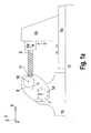
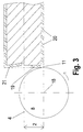
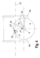
- the axis of rotation is located 4 of the cutter 5 horizontally, but aims not exactly on the center 18 of the journal, but In contrast, is offset parallel, so that the processing point 11, so the contact point between the Stroke pin 8 and the end face of the cutter 5 in an area laterally adjacent to that through the center 18 of the Hublagerzapfens 8 and the axis of rotation 4 of the milling cutter spanned level lies.
- the cutter 5 is in a milling cutter support 6a rotationally drivable recorded, which opposite the cutter support 6b vertically is movable, and wherein the cutter support 6b in the X direction movable relative to the machine bed 12 is.
- the dimensioning of the length of the cutter 5 or the excavation of the cutter supports 6a and 6b in X and Y direction must be such that at the in Y-direction highest and lowest position of the Hublager-Zapfens 8, the end face of the milling cutter 5 the Processing point 11 can achieve as well as at the closest in the X direction or furthest distant position of the pin bearing pin. 8 opposite the cutter 5.
- the cutter axis lies 4 while horizontal, when the pin bearing pin 8 in the nearest in the cutter support 6a, 6b Position, as well as in the opposite order 180 ° twisted, furthest away, provided the pivot axis 17 in this solution or at a distance 2 below the height of the spindle axis. 3 located.
- this is not essential, so that the pivot axis 17 also quite higher or lower.
- the size of the maximum possible swivel angle of the cutter 5 hangs around the pivot axis 17 from the distance between the pivot axis 17 and the end face of the cutter 5 and the stroke of the crankshaft from.
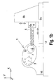
- FIG. 3 shows a detail enlargement from FIG. 1 with the change that in Fig. 3, the rotation axis 4th the milling cutter 5 with respect to the center 18 of the pin bearing journal 8 by the distance 2 up instead of down is offset.
- the adjacent cheek surfaces edit - can the face of the Milling cutter 5 concave lowered conically towards the center be, with a very small angle 21 between the radial plane to the axis of rotation of the cutter 4 and the direction of the end cutting 19 already sufficient is.
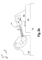
- Fig. 5 shows in plan view a machine for Finishing of crankshafts in one clamping.
- crankshaft 1 is doing with its end pin, which are aligned with the center bearing pin, both sides in Clamping devices 14a, 14b added, and about These are driven in rotation and with controlled C-axis.
- the tensioning devices 14a, 14b are on aligned with each other, facing each other Spindles 13a, 13b added, each in one Headstock 16a, 16b are stored. It is preferable one of the headstocks (16b) movable in Z-direction, around workpieces of different lengths to be able to record.
- the turn-turn unit 24 is about an axis 26, which is parallel to the spindle axis 3 is arranged, pivotally mounted and mounted on the end side in turnbuckle supports 27a, 27b, the synchronous, at least in X, but preferably can also be moved in the Z direction.
- the forehead Drehfräs unit 28 does not have exactly the rotary Wheel syndromem unit 24th for conventional machining of the center bearing pin 7 opposite, but it can be also an angular position of the two attack directions Act on the crankshaft to each other.
- the face-Drehfräs unit 28 consists of a multi-part cutter support, with the cutter support 6c along the machine bed 12 in the Z direction movable, and on this support 6c a milling cutter support 6b in the X direction, ie radially on the Crankshaft to or from this way, be moved can.
- a Milling cutter support 6a linearly movable in Y-direction, in which of the cutter substantially radially to the crankshaft pointing to turning and drifting recorded is.
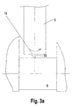
- Fig. 3a shows in the indicated in Fig. 3 Viewing IIIa-IIIa the action of the frontal Cutting edge 19 of the cutter 5 on the lateral surface of the Dowel pin 8.
- the angle between 99 the workpiece surface to be machined and Face of the cutting edge is greater than 90 °, so one so-called positive cutting geometry is given.
- the angle 99 moves in the area between preferably 90 ° and 100 °.
Landscapes
- Engineering & Computer Science (AREA)
- Mechanical Engineering (AREA)
- Milling Processes (AREA)
- Turning (AREA)
- Component Parts Of Construction Machinery (AREA)
- Grinding Of Cylindrical And Plane Surfaces (AREA)
Claims (12)
- Procédé pour l'usinage de pièces (1) dont les surfaces sont aussi bien centrées (7) par rapport à leur axe longitudinal qu'excentriques (8), courbée de manière convexe, par exemple symétriques en rotation,caractérisé en ce quela pièce (1) étant serrée et entraínée en rotation autour d'un axe de broche (3) se trouvant dans le sens longitudinal de l'axe de la pièce,l'usinage des surfaces excentriques d'outil (8) étant effectué au moyen de fraises à surfacer, l'axe de rotation (4) de la fraise (5) étant perpendiculaire à l'axe de la broche (3) (fraises rotatives),a) les surfaces incurvées centrées (7) sont usinées par brochage rotatif, et/ou par brochage rotatif-rotatif (rotation de la pièce et de la broche)b) la pièce est usinée dans une fixation par enlèvement de copeaux.
- Procédé selon la revendication 1, caractérisé en ce que lors de l'usinage des surfaces excentriques (8) sensiblement symétriques en rotation, la distance (2) entre l'axe de rotation (4) de la fraise et le point d'usinage (11) est la plus grande possible.
- Procédé selon l'une des revendications précédentes, caractérisé en ce que l'axe de rotation (4) de la fraise est décalé tangentiellement par rapport au point momentané d'usinage sur la pièce dans le sens de rotation de la pièce.
- Procédé selon l'une des revendications précédentes, caractérisé en ce que l'axe de rotation (4) de la fraise (5) forme un angle droit avec l'axe de broche (3).
- Procédé selon l'une des revendications précédentes, caractérisé en ce que les surfaces de cRté (9), s'étendant radialement à l'axe de broche (3) et attenantes aux surfaces centrées (7) symétriques en rotation, sont usinées au tour, par brochage rotatif et/ou par brochage rotatif-rotatif.
- Procédé selon l'une des revendications précédentes, caractérisé en ce que les surfaces de cRté (10) attenantes et s'étendant radialement à l'axe de broche (3) aux surfaces excentriques (8) symétriques en rotation, sont usinées au moyen de fraises rotatives.
- Procédé selon l'une des revendications précédentes, caractérisé en ce que l'usinage des surfaces (7, 8) sensiblement symétriques en rotation s'effectue en même temps que l'usinage des surfaces radiales de cRté (9, 10) attenantes.
- Procédé selon l'une des revendications précédentes, caractérisé en ce que pour l'usinage de surfaces de pièces au moyen de fraises rotatives, la fraise (5) est mobile linéairement en fonction de la position en rotation de la pièce (1) dans au moins une direction transversale à l'axe longitudinal de la pièce (1) et peut pivoter de manière limitée autour d'un axe C2 (17) se trouvant parallèlement à l'axe longitudinal de la pièce (1), la longueur de la fraise(5) et la possibilité de pivotement étant dimensionnées pour que la fraise (5) puisse atteindre avec sa face avant la surface (8) à usiner de la pièce dans chacune de ses positions de rotation.
- Machine pour l'usinage de pièces dont les surfaces sont aussi bien centrées (7) par rapport à leur axe longitudinal qu'excentriques (8), courbées de manière convexe, par exemple symétriques en rotation, en particulier pour la mise en oeuvre du procédé selon l'une des revendications précédentes, comprenantcaractérisé en ce queun lit de machine (12),au moins une broche porte-pièce (13) entraínée en rotation,au moins un dispositif de serrage pour la pièce (1),un entraínement de l'axe C etau moins une unité formant fraise, l'unité formant fraise étant une unité formant fraise rotative frontale,la fraise (5) étant logée entraínée en rotation dans un porte-fraises (6) qui peut effectuer des déplacements pouvant présenter des composantes aussi bien dans le sens des X que dans le sens des Y,la machine présentant une commande qui permet un positionnement et un déplacement du porte-fraises (6) et ainsi de la fraise (5) en fonction du positionnement et du déplacement de l'axe C et ainsi des surfaces à usiner (8) excentriquement par l'unité avant des fraises-rotatives,
la machine présente une unité rotative à brocher et/ou une unité rotative-rotative à brocher (rotation de la pièce et de la broche). - Machine selon la revendication 9, caractérisé en ce quele porte-fraise (6) est mobile linéairement dans une direction transversale par rapport à l'axe longitudinal de la pièce et la fraise (5) pivote par rapport au porte-fraises(6) autour d'un axe C2 (17) parallèle à la direction longitudinale de la pièce (1).le pivotement maximal de la fraise autour de l'axe C2 (17) et la longueur de la fraise (5) sont dimensionnés pour que la fraise (5) puisse atteindre par sa face avant la surface à usiner de la pièce dans chacune de ses positions possibles de rotation.
- Machine selon la revendication 9 ou 10, caractérisé en ce que les surfaces avant de la fraise (5), présentant les lames avant (19), sont creusées de manière concave en direction de cette surface avant.
- Machine selon la revendication 11, caractérisé en ce que l'angle (21) de creusement dans la surface avant de la fraise (5) est un angle extrêmement faible.
Applications Claiming Priority (2)
| Application Number | Priority Date | Filing Date | Title |
|---|---|---|---|
| DE4446475A DE4446475C2 (de) | 1994-12-23 | 1994-12-23 | Verfahren und Maschine zum Bearbeiten von Werkstücken |
| DE4446475 | 1994-12-23 |
Publications (3)
| Publication Number | Publication Date |
|---|---|
| EP0720883A1 EP0720883A1 (fr) | 1996-07-10 |
| EP0720883B1 EP0720883B1 (fr) | 1999-09-01 |
| EP0720883B2 true EP0720883B2 (fr) | 2005-06-15 |
Family
ID=6537029
Family Applications (1)
| Application Number | Title | Priority Date | Filing Date |
|---|---|---|---|
| EP95120291A Expired - Lifetime EP0720883B2 (fr) | 1994-12-23 | 1995-12-21 | Méthode et dispositif à travailler des pièces à surfaces excentriques principalement à surface de rotation |
Country Status (5)
| Country | Link |
|---|---|
| US (1) | US5765270A (fr) |
| EP (1) | EP0720883B2 (fr) |
| AT (1) | ATE183954T1 (fr) |
| DE (2) | DE4446475C2 (fr) |
| ES (1) | ES2139137T5 (fr) |
Families Citing this family (26)
| Publication number | Priority date | Publication date | Assignee | Title |
|---|---|---|---|---|
| DE59605652D1 (de) * | 1995-06-06 | 2000-08-31 | Widia Gmbh | Verfahren zur spanenden bearbeitung von zylindrischen konturen, vorrichtung zur durchführung des verfahrens und schneideinsatz hierzu |
| DE19626627C1 (de) * | 1996-07-02 | 1997-09-18 | Boehringer Werkzeugmaschinen | Fräsmaschine |
| DE19626609C2 (de) * | 1996-07-02 | 2000-03-09 | Boehringer Werkzeugmaschinen | Mehrfachfräsen an Kurbelwellen |
| DE19626608B4 (de) * | 1996-07-02 | 2004-11-11 | Boehringer Werkzeugmaschinen Gmbh | Verfahren zur spanenden Bearbeitung |
| JP3685879B2 (ja) * | 1996-07-26 | 2005-08-24 | 東芝機械株式会社 | 旋回可能な主軸頭を有する工作機械 |
| IT1285484B1 (it) * | 1996-10-08 | 1998-06-08 | Balance Systems Srl | Dispositivo di equilibratura di un rotore mediante asportazione di materiale |
| DE19722454A1 (de) * | 1997-05-28 | 1998-12-10 | Boehringer Werkzeugmaschinen | Verfahren zum Steuern der Bearbeitung eines Werkstückes |
| JP3807647B2 (ja) * | 1997-11-11 | 2006-08-09 | コマツ工機株式会社 | カムシャフト加工機 |
| DE19749939C2 (de) * | 1997-11-11 | 2003-10-23 | Boehringer Werkzeugmaschinen | Verfahren zur Bearbeitung von Werkstücken |
| DE19749940C5 (de) * | 1997-11-11 | 2010-05-20 | Boehringer Werkzeugmaschinen Gmbh | Verfahren zur verwendungsfähigen Fertigbearbeitung von Kurbelwellen |
| ES2209096T5 (es) * | 1998-11-20 | 2007-11-01 | Mikron Sa Agno | Dispositivo para la generacion de un movimiento relativo. |
| DE102004026675C5 (de) * | 2004-05-28 | 2010-01-21 | J.G. WEISSER SöHNE GMBH & CO. KG | Verfahren und Vorrichtung zum spanenden Bearbeiten rotationssymmetrischer Flächen eines Werkstückes |
| DE102004043404A1 (de) * | 2004-09-08 | 2006-03-09 | Volkswagen Ag | Verfahren zur Bearbeitung von Rotationsteilen |
| DE102004057111A1 (de) | 2004-11-26 | 2006-06-01 | Niles-Simmons Industrieanlagen Gmbh | Verfahren zum Zwischenbearbeiten von Wellen |
| DE102006024715B4 (de) * | 2006-05-26 | 2008-07-24 | Niles-Simmons Industrieanlagen Gmbh | Verfahren zum Bearbeiten der Lagersitze der Haupt- und Hublager von Kurbelwellen sowie Werkzeugmaschine zur Durchführung des Verfahrens |
| DE102009039346A1 (de) * | 2009-08-29 | 2011-03-03 | J. G. WEISSER SÖHNE GmbH & Co. KG | Verfahren zur spanenden Drehbearbeitung und Drehbearbeitungsvorrichtung |
| CN102548698B (zh) * | 2009-09-25 | 2014-09-10 | 格里森工场 | 用于齿轮的倒角和/或去毛刺的设备 |
| DE102011113758B4 (de) * | 2011-09-18 | 2020-12-31 | Mag Ias Gmbh | Verfahren und Vorrichtung zur Fertigbearbeitung von Werkstücken |
| DE102011113756B4 (de) * | 2011-09-18 | 2020-12-31 | Mag Ias Gmbh | Verfahren und Vorrichtung zur Fertigbearbeitung von Werkstücken |
| DE102011113757B4 (de) * | 2011-09-18 | 2020-12-31 | Mag Ias Gmbh | Verfahren und Vorrichtung zur Fertigbearbeitung von Werkstücken |
| DE102011089654B4 (de) | 2011-12-22 | 2015-01-29 | Erwin Junker Maschinenfabrik Gmbh | Verfahren zur drehbearbeitung von planschultern an den wangen einer kurbelwelle, verwendung des verfahrens zur komplettbearbeitung von kurbelwellenrohlingen sowie kurbelwellen-drehmaschine zur drehbearbeitung der planschultern |
| KR20170129163A (ko) * | 2015-02-24 | 2017-11-24 | 반두리트 게엠베하 하르트메탈 운트 디아만트베르크초이그 | 회전 피가공재를 기계가공하기 위한 디바이스, 방법 및 절단 플레이트 |
| DE102017115089B4 (de) * | 2017-07-06 | 2019-04-25 | Klaus Union Gmbh & Co. Kg | Verfahren zur Herstellung eines Rotors für eine Schraubenspindelpumpe |
| DE202018104142U1 (de) * | 2018-07-18 | 2019-10-22 | Vogelsang Gmbh & Co. Kg | Rotor für eine Exzenterschneckenpumpe |
| CN112077390B (zh) * | 2020-09-18 | 2021-08-17 | 中国航发沈阳黎明航空发动机有限责任公司 | 一种机匣偏心槽的加工方法 |
| DE102021131427A1 (de) | 2021-11-30 | 2023-06-01 | Vogelsang Gmbh & Co. Kg | Exzenterschneckenpumpe mit Arbeitszustellung und Ruhezustellung sowie Verfahren zum Steuern der Exzenterschneckenpumpe |
Citations (3)
| Publication number | Priority date | Publication date | Assignee | Title |
|---|---|---|---|---|
| EP0018000A1 (fr) † | 1979-04-18 | 1980-10-29 | Gebr. Heller Maschinenfabrik GmbH | Machine à fraiser les vilebrequins |
| WO1985004126A1 (fr) † | 1984-03-17 | 1985-09-26 | H. Wohlenberg Kg Gmbh & Co. | Tour |
| DE3831613A1 (de) † | 1988-07-27 | 1990-02-08 | Heyligenstaedt Gmbh & Co Kg | Drehmaschine mit einem werkzeugsupport |
Family Cites Families (22)
| Publication number | Priority date | Publication date | Assignee | Title |
|---|---|---|---|---|
| DE272225C (fr) * | 1911-02-13 | |||
| US1137917A (en) * | 1914-05-20 | 1915-05-04 | Arvel T Sink | Milling-machine. |
| DE417446C (de) * | 1922-03-30 | 1925-08-12 | Automatic Refrigerating Compan | Luftkaeltemaschine |
| US2126462A (en) * | 1936-02-10 | 1938-08-09 | Rk Leblond Machine Tool Co | Orbital broaching lathe |
| US2650522A (en) * | 1946-10-21 | 1953-09-01 | Gisholt Machine Co | Turn milling machine |
| DE1236303B (de) * | 1956-07-07 | 1967-03-09 | August Gunnar Ferdinand Wallgr | Vorrichtung zum Herstellen von Rotationsflaechen an Kurbelwellen oder aehnlichen Werkstuecken |
| AT286067B (de) * | 1968-06-21 | 1970-11-25 | Skoda Np | Fraesmaschine fuer kurbelwellen od. dgl |
| AT353073B (de) * | 1978-04-18 | 1979-10-25 | Gfm Fertigungstechnik | Verfahren zum bearbeiten von kurbelwellen |
| JPS563102A (en) * | 1979-06-22 | 1981-01-13 | Komatsu Ltd | Crankshaft machining machine |
| JPS6025610A (ja) * | 1983-07-20 | 1985-02-08 | Toyoda Mach Works Ltd | カムミ−リングマシン |
| DE3328327C2 (de) * | 1983-08-05 | 1985-10-10 | Index-Werke Kg Hahn & Tessky, 7300 Esslingen | Vorrichtung zum spanabhebenden Bearbeiten eines Werkstücks sowie NC-gesteuerte Drehmaschine zur Druchführung eines solchen Verfahrens |
| AT378710B (de) * | 1983-12-01 | 1985-09-25 | Voest Alpine Ag | Drehmaschine |
| US4801226A (en) * | 1987-01-09 | 1989-01-31 | Turn-Broach, Inc. | Crankshaft broaching machine and method |
| US4790698A (en) * | 1987-05-13 | 1988-12-13 | Cm Systems, Incorporated | Monotonic cutting machine |
| DE3809619A1 (de) * | 1988-03-22 | 1989-10-12 | Boehringer Werkzeugmaschinen | Verfahren und vorrichtung zur bearbeitung von rotationssymmetrischen bauteilen |
| FR2641220B1 (fr) * | 1988-05-25 | 1994-06-03 | Somab Sa | Machine-outil multifonctions permettant des usinages complexes de pieces longues |
| DE3901888A1 (de) * | 1989-01-23 | 1990-08-02 | Boehringer Werkzeugmaschinen | Werkzeugbestueckte drehraeummaschine |
| DE3930489C2 (de) * | 1989-09-12 | 1993-11-18 | Boehringer Werkzeugmaschinen | Verfahren und Werkzeugmaschine zum Fertigbearbeiten von Lagerzapfen |
| DE4013327C2 (de) * | 1990-04-26 | 1999-12-30 | Werner Hermann Wera Werke | Maschine zur spanenden Metallbearbeitung |
| JPH05200601A (ja) * | 1992-01-24 | 1993-08-10 | Takizawa Tekkosho:Kk | 工作機械 |
| EP0672491A1 (fr) * | 1994-02-17 | 1995-09-20 | Maschinenfabrik Ravensburg AG | Méthode et machine-outil pour le chambrage de vilebrequins |
| DE4418823C1 (de) * | 1994-05-30 | 1995-07-27 | Niles Simmons Industrieanlagen | Radsatzbearbeitungsverfahren und Radsatzbearbeitungsmaschine |
-
1994
- 1994-12-23 DE DE4446475A patent/DE4446475C2/de not_active Revoked
-
1995
- 1995-12-21 EP EP95120291A patent/EP0720883B2/fr not_active Expired - Lifetime
- 1995-12-21 DE DE59506724T patent/DE59506724D1/de not_active Expired - Lifetime
- 1995-12-21 ES ES95120291T patent/ES2139137T5/es not_active Expired - Lifetime
- 1995-12-21 AT AT95120291T patent/ATE183954T1/de not_active IP Right Cessation
- 1995-12-22 US US08/577,711 patent/US5765270A/en not_active Expired - Lifetime
Patent Citations (3)
| Publication number | Priority date | Publication date | Assignee | Title |
|---|---|---|---|---|
| EP0018000A1 (fr) † | 1979-04-18 | 1980-10-29 | Gebr. Heller Maschinenfabrik GmbH | Machine à fraiser les vilebrequins |
| WO1985004126A1 (fr) † | 1984-03-17 | 1985-09-26 | H. Wohlenberg Kg Gmbh & Co. | Tour |
| DE3831613A1 (de) † | 1988-07-27 | 1990-02-08 | Heyligenstaedt Gmbh & Co Kg | Drehmaschine mit einem werkzeugsupport |
Non-Patent Citations (7)
| Title |
|---|
| DIN 1880, Teil 2, Dezember 1981, Seite 3 † |
| DIN 69844, Teil2, November 1987, Seite 5-8 † |
| Dubbel, Taschenbuch für den Maschinenbau, 17 Aufl. 1990, Kapitel S 4.2.4 : Fräsen, Seite S45 † |
| König, "Fertigungsverfahren", 1990, Bd1 , Kap. 8.2.2.8, Drehfräsen, Seite 310-314 † |
| König/Wand "Fräsen statt Drehen : Drefräsen", Industrieanzeiger Nr. 12 vom 11.02.1986 † |
| Machinery and production engineering, August 1987, Seite 293 † |
| Prospekt Fa. Heyligenstaedt : Aus Freude am Drehen "Die HEYNUMATen", Dricknummer 15 001 292 † |
Also Published As
| Publication number | Publication date |
|---|---|
| EP0720883B1 (fr) | 1999-09-01 |
| DE4446475C2 (de) | 2000-06-21 |
| ATE183954T1 (de) | 1999-09-15 |
| DE59506724D1 (de) | 1999-10-07 |
| DE4446475A1 (de) | 1996-06-27 |
| US5765270A (en) | 1998-06-16 |
| ES2139137T5 (es) | 2006-03-16 |
| EP0720883A1 (fr) | 1996-07-10 |
| ES2139137T3 (es) | 2000-02-01 |
Similar Documents
| Publication | Publication Date | Title |
|---|---|---|
| EP0720883B2 (fr) | Méthode et dispositif à travailler des pièces à surfaces excentriques principalement à surface de rotation | |
| DE19749939C2 (de) | Verfahren zur Bearbeitung von Werkstücken | |
| EP0417446B1 (fr) | Usinage de vilebrequin en 3 phases | |
| EP0901857A1 (fr) | Tourelle porte outil pour machine outil ainsi que tour ayant une telle tourelle | |
| EP1330338B1 (fr) | Machine polyvalente | |
| DE19723702A1 (de) | CNC-Dreh- und Fräsbearbeitungszentrum | |
| DE102016114252B4 (de) | Innenfräs-Maschine | |
| EP1570946B1 (fr) | Machine-outil avec au moins deux broches porte-outils et un disque à outils | |
| EP1286802B1 (fr) | Fraise trois tailles | |
| DE202016103064U1 (de) | Vorrichtung zur spanenden Bearbeitung eines rotierenden Werkstücks | |
| CH669924A5 (fr) | ||
| DE4236866A1 (de) | Drehmaschine | |
| DE1777439A1 (de) | Mehrzweck-werkzeugmaschine | |
| DE102009039346A1 (de) | Verfahren zur spanenden Drehbearbeitung und Drehbearbeitungsvorrichtung | |
| EP0868242A2 (fr) | Procede et dispositif de fraisage par rotation | |
| DE3136372A1 (de) | Doppelstaender-portalschleifmaschine | |
| EP0885082B1 (fr) | Procede et dispositif pour usiner des logements de palier de vilebrequins | |
| EP0685283B1 (fr) | Procédé d'usinage d'essieux montés et machine pour l'usinage d'essieux montés | |
| EP1722912B1 (fr) | Procede pour fabriquer des glissieres profilees pour elements d' articulation | |
| EP0717669B1 (fr) | Dispositif d'usinage de pieces sur un tour automatique a commande numerique et tour automatique a commande numerique | |
| EP4615652A1 (fr) | Procédé d'usinage de denture avec chanfreinage ultérieur | |
| WO2006002862A1 (fr) | Outil et dispositif pour usiner des pieces a usiner | |
| EP0119236B1 (fr) | Tour automatique a broches multiples | |
| DE3611103A1 (de) | Schleifmaschine | |
| DE19520058A1 (de) | Schneideinsatz |
Legal Events
| Date | Code | Title | Description |
|---|---|---|---|
| PUAI | Public reference made under article 153(3) epc to a published international application that has entered the european phase |
Free format text: ORIGINAL CODE: 0009012 |
|
| AK | Designated contracting states |
Kind code of ref document: A1 Designated state(s): AT DE ES FR GB IT |
|
| 17P | Request for examination filed |
Effective date: 19960610 |
|
| 17Q | First examination report despatched |
Effective date: 19970813 |
|
| GRAG | Despatch of communication of intention to grant |
Free format text: ORIGINAL CODE: EPIDOS AGRA |
|
| GRAG | Despatch of communication of intention to grant |
Free format text: ORIGINAL CODE: EPIDOS AGRA |
|
| GRAH | Despatch of communication of intention to grant a patent |
Free format text: ORIGINAL CODE: EPIDOS IGRA |
|
| GRAH | Despatch of communication of intention to grant a patent |
Free format text: ORIGINAL CODE: EPIDOS IGRA |
|
| GRAA | (expected) grant |
Free format text: ORIGINAL CODE: 0009210 |
|
| AK | Designated contracting states |
Kind code of ref document: B1 Designated state(s): AT DE ES FR GB IT |
|
| REF | Corresponds to: |
Ref document number: 183954 Country of ref document: AT Date of ref document: 19990915 Kind code of ref document: T |
|
| REF | Corresponds to: |
Ref document number: 59506724 Country of ref document: DE Date of ref document: 19991007 |
|
| GBT | Gb: translation of ep patent filed (gb section 77(6)(a)/1977) |
Effective date: 19991026 |
|
| ITF | It: translation for a ep patent filed | ||
| ET | Fr: translation filed | ||
| REG | Reference to a national code |
Ref country code: ES Ref legal event code: FG2A Ref document number: 2139137 Country of ref document: ES Kind code of ref document: T3 |
|
| PLBQ | Unpublished change to opponent data |
Free format text: ORIGINAL CODE: EPIDOS OPPO |
|
| PLBI | Opposition filed |
Free format text: ORIGINAL CODE: 0009260 |
|
| PLBF | Reply of patent proprietor to notice(s) of opposition |
Free format text: ORIGINAL CODE: EPIDOS OBSO |
|
| 26 | Opposition filed |
Opponent name: HEYLIGENSTAEDT GMBH & CO KG I.K Effective date: 20000526 Opponent name: GEBR. HELLER MASCHINENFABRIK GMBH Effective date: 20000527 |
|
| PLBF | Reply of patent proprietor to notice(s) of opposition |
Free format text: ORIGINAL CODE: EPIDOS OBSO |
|
| PLBF | Reply of patent proprietor to notice(s) of opposition |
Free format text: ORIGINAL CODE: EPIDOS OBSO |
|
| RDAH | Patent revoked |
Free format text: ORIGINAL CODE: EPIDOS REVO |
|
| APAC | Appeal dossier modified |
Free format text: ORIGINAL CODE: EPIDOS NOAPO |
|
| APAE | Appeal reference modified |
Free format text: ORIGINAL CODE: EPIDOS REFNO |
|
| APAC | Appeal dossier modified |
Free format text: ORIGINAL CODE: EPIDOS NOAPO |
|
| REG | Reference to a national code |
Ref country code: GB Ref legal event code: IF02 |
|
| APBU | Appeal procedure closed |
Free format text: ORIGINAL CODE: EPIDOSNNOA9O |
|
| PUAH | Patent maintained in amended form |
Free format text: ORIGINAL CODE: 0009272 |
|
| STAA | Information on the status of an ep patent application or granted ep patent |
Free format text: STATUS: PATENT MAINTAINED AS AMENDED |
|
| 27A | Patent maintained in amended form |
Effective date: 20050615 |
|
| AK | Designated contracting states |
Kind code of ref document: B2 Designated state(s): AT DE ES FR GB IT |
|
| GBTA | Gb: translation of amended ep patent filed (gb section 77(6)(b)/1977) | ||
| APAH | Appeal reference modified |
Free format text: ORIGINAL CODE: EPIDOSCREFNO |
|
| PGFP | Annual fee paid to national office [announced via postgrant information from national office to epo] |
Ref country code: GB Payment date: 20051220 Year of fee payment: 11 |
|
| REG | Reference to a national code |
Ref country code: ES Ref legal event code: DC2A Date of ref document: 20050908 Kind code of ref document: T5 |
|
| ET3 | Fr: translation filed ** decision concerning opposition | ||
| GBPC | Gb: european patent ceased through non-payment of renewal fee |
Effective date: 20061221 |
|
| PG25 | Lapsed in a contracting state [announced via postgrant information from national office to epo] |
Ref country code: GB Free format text: LAPSE BECAUSE OF NON-PAYMENT OF DUE FEES Effective date: 20061221 |
|
| PGFP | Annual fee paid to national office [announced via postgrant information from national office to epo] |
Ref country code: ES Payment date: 20091218 Year of fee payment: 15 Ref country code: AT Payment date: 20091217 Year of fee payment: 15 |
|
| PGFP | Annual fee paid to national office [announced via postgrant information from national office to epo] |
Ref country code: IT Payment date: 20091224 Year of fee payment: 15 Ref country code: FR Payment date: 20100105 Year of fee payment: 15 |
|
| PGFP | Annual fee paid to national office [announced via postgrant information from national office to epo] |
Ref country code: DE Payment date: 20091229 Year of fee payment: 15 |
|
| REG | Reference to a national code |
Ref country code: DE Ref legal event code: R081 Ref document number: 59506724 Country of ref document: DE Owner name: MAG IAS GMBH, DE Free format text: FORMER OWNER: BOEHRINGER WERKZEUGMASCHINEN GMBH, 73033 GOEPPINGEN, DE Effective date: 20110318 |
|
| PG25 | Lapsed in a contracting state [announced via postgrant information from national office to epo] |
Ref country code: AT Free format text: LAPSE BECAUSE OF NON-PAYMENT OF DUE FEES Effective date: 20101221 |
|
| REG | Reference to a national code |
Ref country code: FR Ref legal event code: ST Effective date: 20110831 |
|
| PG25 | Lapsed in a contracting state [announced via postgrant information from national office to epo] |
Ref country code: FR Free format text: LAPSE BECAUSE OF NON-PAYMENT OF DUE FEES Effective date: 20110103 |
|
| REG | Reference to a national code |
Ref country code: DE Ref legal event code: R119 Ref document number: 59506724 Country of ref document: DE Effective date: 20110701 |
|
| PG25 | Lapsed in a contracting state [announced via postgrant information from national office to epo] |
Ref country code: DE Free format text: LAPSE BECAUSE OF NON-PAYMENT OF DUE FEES Effective date: 20110701 |
|
| PG25 | Lapsed in a contracting state [announced via postgrant information from national office to epo] |
Ref country code: IT Free format text: LAPSE BECAUSE OF NON-PAYMENT OF DUE FEES Effective date: 20101221 |
|
| REG | Reference to a national code |
Ref country code: ES Ref legal event code: FD2A Effective date: 20120206 |
|
| PG25 | Lapsed in a contracting state [announced via postgrant information from national office to epo] |
Ref country code: ES Free format text: LAPSE BECAUSE OF NON-PAYMENT OF DUE FEES Effective date: 20101222 |